PARK / NEUTRAL POSITION SWITCH REMOVAL

-
DISCONNECT CABLE FROM NEGATIVE BATTERY TERMINAL
Note
When disconnecting the cable, some systems need to be initialized after the cable is reconnected Click here.
-
REMOVE WINDSHIELD WIPER MOTOR AND LINK ASSEMBLY
-
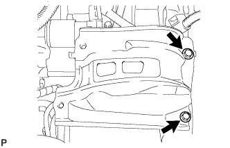
SEPARATE BRAKE MASTER CYLINDER RESERVOIR BRACKET
-
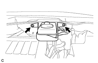
Remove the 2 nuts and separate the brake master cylinder reservoir with bracket from the outer cowl top panel.
-
-
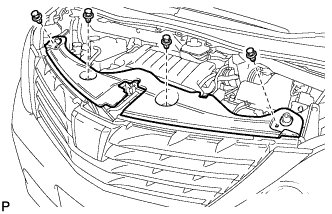
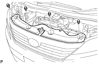
REMOVE OUTER COWL TOP PANEL SUB-ASSEMBLY
-
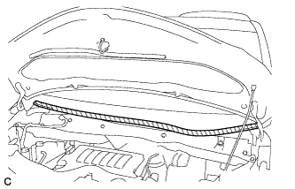
Apply protective tape as shown in the illustration.
Text in Illustration 
Protective Tape -
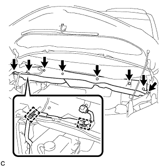
Disconnect the 2 clamps from the outer cowl top panel.
-
Remove the 8 bolts.
-
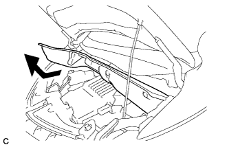
Remove the outer cowl top panel as shown in the illustration.
-
-
REMOVE RADIATOR COVER SUB-ASSEMBLY (for ALPHARD)
-
Using a clip remover, remove the 4 clips and radiator cover sub-assembly.
-
-
REMOVE RADIATOR COVER SUB-ASSEMBLY (for VELLFIRE)
-
Using a clip remover, remove the 4 clips and radiator cover sub-assembly.
-
-
REMOVE BATTERY
-
Disconnect the positive (+) cable to the battery positive (+) terminal.
-
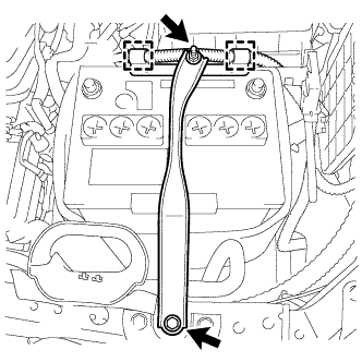
Disconnect the 2 wire clamps.
-
Loosen the nut, and remove the bolt with the battery clamp.
-
Remove the battery, battery insulator and battery tray.
-
-
REMOVE AIR CLEANER CAP SUB-ASSEMBLY
-
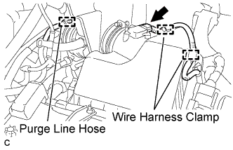
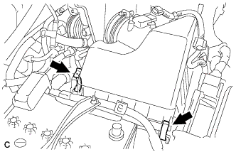
Separate the mass air flow meter connector and 2 wire harness clamps.
-
Separate the purge line hose.
-
Separate the ventilation hose.
-
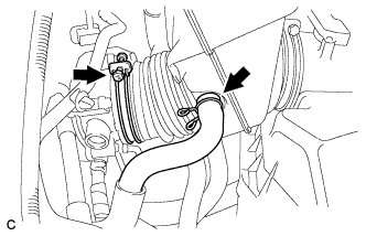
Loosen the hose clamp and separate the air cleaner hose from the throttle body.
-
Release the 2 clamps and remove the air cleaner cap sub-assembly.
-
-
REMOVE AIR CLEANER CASE
-
Remove the air cleaner filter element.
-
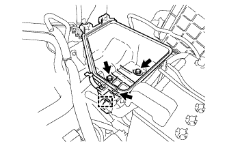
Disconnect the wire clamp.
-
Remove the 3 bolts and air cleaner case.
-
-
REMOVE BATTERY CARRIER
-
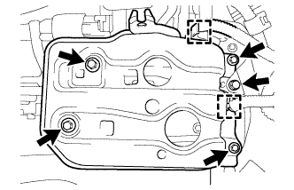
Detach the 2 wire harness clamps.
-
Remove the 5 bolts and battery carrier.
-
-
REMOVE BATTERY CARRIER SUPPORT
-
Remove the 2 bolts and battery carrier support.
-
-
REMOVE ENGINE MOUNTING INSULATOR LH
-
Support the oil pan with a jack, placing a wooden block between the oil pan and jack.
-
Remove the through bolt and nut, and separate the engine mounting insulator LH.
-
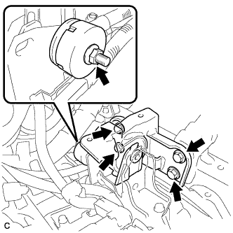
Remove the bolt and clamp, and separate the wire harness protector from the wire harness bracket.
-
Remove the bolt, 2 clamps and wire harness bracket from the engine mounting insulator LH.
-
Tilt the automatic transaxle downward.
Note
Do not lower the automatic transaxle more than necessary.
-
Remove the nut and engine mounting damper.
-
Remove the 4 bolts and engine mounting insulator LH.
-
-
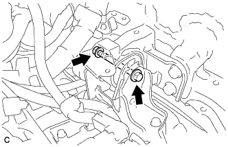
REMOVE ENGINE MOUNTING BRACKET LH
-
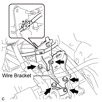
Remove the bolt and engine wire bracket from the engine mounting bracket LH.
-
Disconnect the clamp from the engine mounting bracket LH.
-
Remove the 4 bolts and engine mounting bracket LH from the automatic transaxle assembly.
-
-
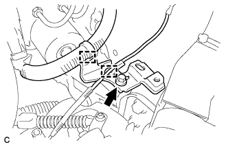
REMOVE PARK/NEUTRAL POSITION SWITCH ASSEMBLY
-
Move the shift lever to N.
-
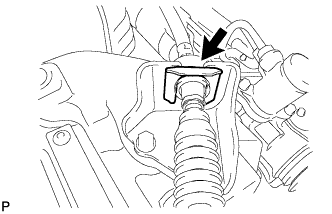
Remove the clip from the transmission cable bracket.
-
Remove the nut and transmission control cable assembly from the control shaft lever.
-
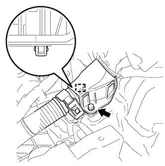
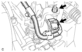
Disconnect the park/neutral position switch connector and clamp.
-
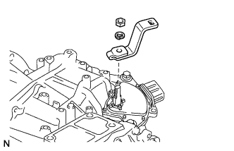
Remove the nut, washer and control shaft lever from the control shaft.
-
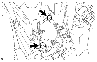
Remove the 2 bolts and park/neutral position switch from the control shaft.
Note
Before removing the park/neutral position switch, remove any dirt or rust on the installation portion of the control shaft. Be sure to remove the switch straight along the shaft while being careful not to deform the plate spring that supports the shaft. If the plate spring is deformed, the park/neutral position switch cannot be reinstalled correctly.
-