- Click here
INSTALL ENGINE SWITCH (for RHD)
-
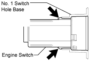
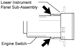
Attach the 2 claws to install the engine switch.
-
- Click here
INSTALL NO. 1 SWITCH HOLE BASE (for RHD)
-
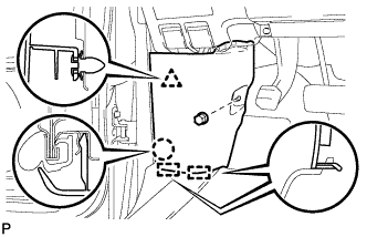
Connect each connector.
-
Engage the 6 claws and 3 guides to install the No. 1 switch hole base.
-
- Click here
INSTALL NO. 1 INSTRUMENT CLUSTER FINISH PANEL GARNISH (for RHD)
-
Connect the connector.
-
Engage the 4 claws to install the No. 1 instrument cluster finish panel garnish.
-
- Click here
INSTALL CENTER FLOOR CARPET COVER RH (for RHD)
-
Engage the 4 claws.
-
Install the center floor carpet cover RH with the 2 clips.
-
- Click here
INSTALL LOWER INSTRUMENT PANEL FINISH PANEL (for RHD)
-
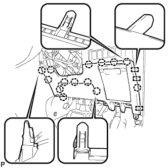
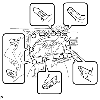
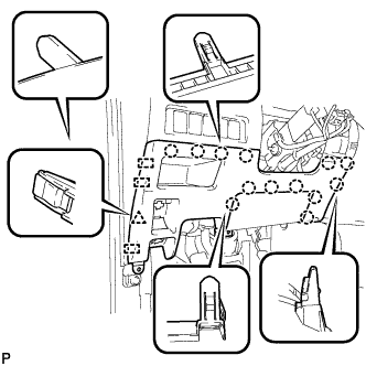
Engage the 3 guides and 14 claws.
Tip:Make sure that all claws around the entire circumference of the driver side knee airbag assembly are fully engaged.
Note:Make sure that the claws are fully engaged.
-
Install the lower instrument panel finish panel with the 3 screws <B>.
-

Engage the 3 claws and the fuel lid lock control cable assembly.
-
Engage the 3 claws and the hood lock control cable assembly.
-
- Click here
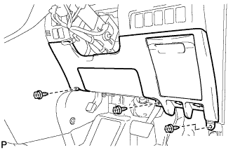
INSTALL NO. 1 INSTRUMENT PANEL UNDER COVER SUB-ASSEMBLY (for RHD)
-

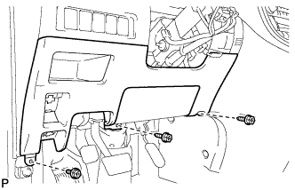
Remove the 2 screws <B>.
-
Disengage the 2 claws and 2 guides.
-
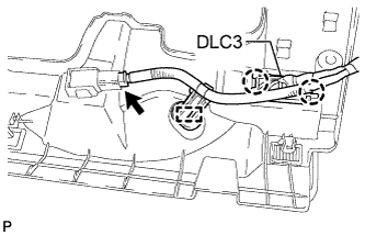
Disengage the 2 claws and disconnect the DLC3.
-
Disengage the clamp.
-
Disconnect each connector and remove the No. 1 instrument panel under cover sub-assembly.
-
- Click here
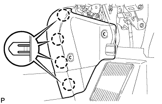
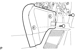
INSTALL COWL SIDE TRIM BOARD RH (for RHD)
-

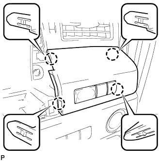
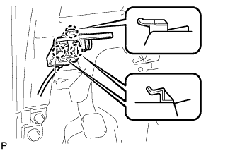
Engage the 2 guides, claw and clip to install the cowl side trim board RH.
-
Install the clip(A).
-
- Click here
INSTALL NO. 1 INSTRUMENT CLUSTER FINISH PANEL (for RHD)
-
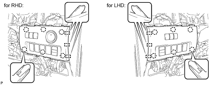
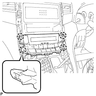
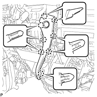
Engage the 11 claws and 2 guides to install the No. 1 instrument cluster finish panel.
-
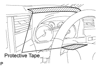
Remove the protective tape from the steering column cover.
-
- Click here
INSTALL ENGINE SWITCH (for LHD)
-
Connect the connector.
-
Attach the 2 claws to install the engine switch.
-
- Click here
INSTALL AIR CONDITIONING CONTROL ASSEMBLY (for LHD)
-
Connect the connector.
-
Engage the 4 claws to install the air conditioning control assembly.
-
- Click here
INSTALL NO. 2 INSTRUMENT CLUSTER FINISH PANEL GARNISH (for LHD)
-
Engage the 8 claws to install the No. 2 instrument cluster finish panel garnish.
Note:Make sure that the claws are fully engaged.
-
- Click here
INSTALL CENTER INSTRUMENT CLUSTER FINISH PANEL SUB-ASSEMBLY (for LHD)
-
Connect the connector.
-
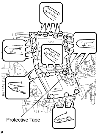
Engage the 23 claws to install the center instrument cluster finish panel sub-assembly.
Note:
-
When installing the center instrument cluster finish panel sub-assembly, make sure to press the upper middle part firmly.
-
Make sure that the claws are fully engaged.
-
-
Remove the applied protective tape.
-
Move the shift lever to P.
-
- Click here
INSTALL INSTRUMENT CLUSTER FINISH PANEL ASSEMBLY (for LHD)
-
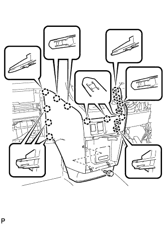
Engage the 15 claws.
Tip:Before engaging the 15 claws, make sure that the claws are positioned correctly.
Note:Make sure that the claws are fully engaged.
-
Install the instrument cluster finish panel assembly with the bolt <C>.
-
- Click here
INSTALL SHIFT LEVER KNOB SUB-ASSEMBLY (for LHD)
-
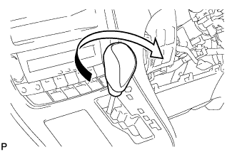
Turn the shift lever knob clockwise to install the shift lever knob sub-assembly.
-
- Click here
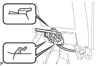
INSTALL INSTRUMENT PANEL BOX ASSEMBLY (for LHD)
-
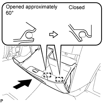
With the instrument panel box assembly opened approximately 60° from its closed position, engage the 2 hinges horizontally.
Note:Engaging the hinges from the top will deform the hinges. Be sure to install the instrument panel box assembly horizontally.
-
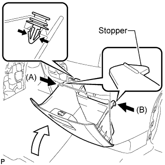
Install the damper clip.
-
Slightly bend stoppers (A) and (B) in the directions indicated by the arrows in the illustration and engage the stoppers to install the instrument panel box assembly.
-
- Click here
INSTALL GLOVE COMPARTMENT DOOR ASSEMBLY (for LHD)
-
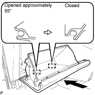
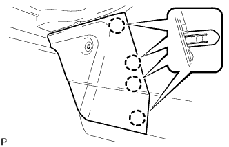
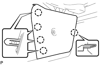
With the glove compartment door assembly opened approximately 55° from its closed position, engage the 2 hinges horizontally.
Note:Engaging the hinges from the top will deform the hinges. Be sure to install the glove compartment door assembly horizontally.
-
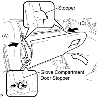
Slightly bend stoppers (A) and (B) in the directions indicated by the arrows in the illustration and engage the stoppers to install the glove compartment door assembly.
-
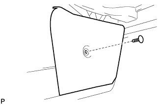
Engage the claw and connect the glove compartment door stopper.
-
- Click here
INSTALL CENTER FLOOR CARPET COVER LH (for LHD)
-
Engage the 4 claws.
-

Install the center floor carpet cover LH with the clip.
-
- Click here
INSTALL CENTER FLOOR CARPET COVER RH (for LHD)
-
Engage the 5 claws.
-
Install the center floor carpet cover RH with the clip.
-
- Click here
INSTALL LOWER INSTRUMENT PANEL FINISH PANEL (for LHD)
-
Engage the 3 guides, 13 claws and clip.
Tip:Make sure that all claws around the entire circumference of the driver side knee airbag assembly are fully engaged.
Note:Make sure that the claws are fully engaged.
-
Install the lower instrument panel finish panel with the 3 screws <B>.
-

Connect the fuel filler opening lid lock sub-assembly to the fuel lid lock open lever sub-assembly.
-
Engage the 3 claws and the fuel lid lock control cable assembly.
-

Engage the 3 claws and the hood lock control cable assembly.
-
- Click here
INSTALL NO. 1 INSTRUMENT PANEL UNDER COVER SUB-ASSEMBLY (for LHD)
-
Engage the clamp.
-
Connect each connector.
-

Engage the 2 claws and guide.
Note:Make sure that the claws are fully engaged.
-
Install the No. 1 instrument panel under cover sub-assembly with the 2 screws <B>.
-
- Click here
INSTALL NO. 1 INSTRUMENT CLUSTER FINISH PANEL (for LHD)
-
Engage the 11 claws and 2 guides to install the No. 1 instrument cluster finish panel.
-
Remove the protective tape from the steering column cover.
-
- Click here
INSTALL COWL SIDE TRIM BOARD LH (for LHD)
-
Engage the 2 guides, claw and clip to install the cowl side trim board LH.
-
Install the clip(A).
-
- Click here
CONNECT CABLE TO NEGATIVE BATTERY TERMINAL
-
Connect the cable to the negative (-) battery terminal.
Note:When disconnecting the cable, some systems need to be initialized after the cable is reconnected (Click here).
-