RADIATOR INSTALLATION

-
INSTALL RADIATOR ASSEMBLY
-
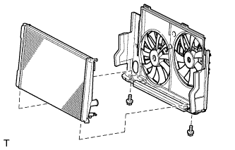
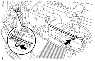
Install the fan shroud with fan motors to the radiator assembly with the 2 bolts.
- Torque:
- 11 N*m { 112 kgf*cm, 8 ft.*lbf }
-
Text in Illustration *1 Matchmark w/ Oil Cooler:
-
Align the matchmark as shown in the illustration. Connect the 2 oil cooler hoses.
-
Install the oil cooler pipe with the 3 bolts.
- Torque:
- 5.5 N*m { 56 kgf*cm, 49 in.*lbf }
-
-
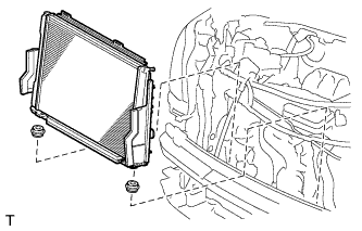
Install the 2 lower radiator supports.
Note
Do not apply any excessive force to the cooler condenser assembly or pipe when installing the radiator assembly.
-
Install the radiator with fan shroud and fan motors.
-
-
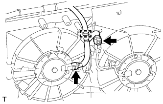
INSTALL NO. 2 FAN SHROUD
-
Install the No. 2 fan shroud with the 2 bolts and 2 claws.
- Torque:
- 11 N*m { 112 kgf*cm, 8 ft.*lbf }
-
-
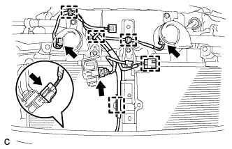
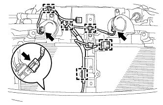
INSTALL UPPER RADIATOR SUPPORT SUB-ASSEMBLY
-
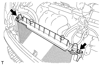
Install the 2 radiator support cushions.
-
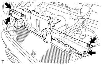
Install the upper radiator support sub-assembly with the 4 bolts.
- Torque:
- 30 N*m { 306 kgf*cm, 22 ft.*lbf }
-
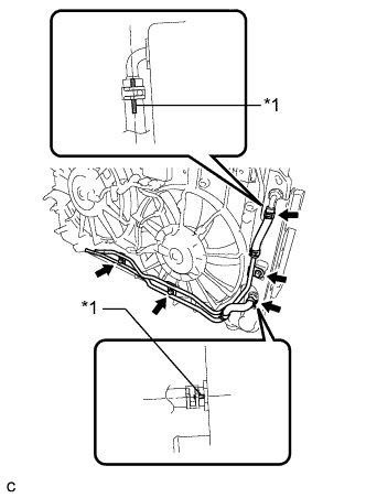
Connect the 6 wire harness clamps.
-
Connect the 2 connectors and clamp.
-
-
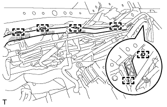
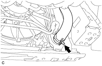
CONNECT NO. 1 WATER BY-PASS PIPE
-
Install the No. 1 water by-pass pipe with the 2 bolts.
- Torque:
- 12 N*m { 122 kgf*cm, 9 ft.*lbf }
-
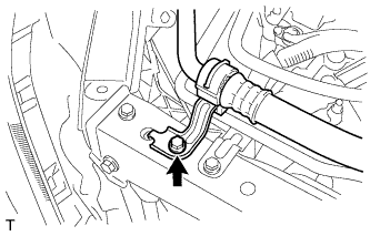
Install the No. 1 cooler refrigerant suction hose with the bolt.
- Torque:
- 9.8 N*m { 100 kgf*cm, 87 in.*lbf }
-
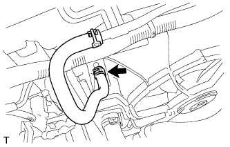
Connect the No. 3 water by-pass hose.
-
-
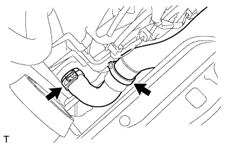
CONNECT NO. 2 WATER BY-PASS HOSE
-
Connect the No. 2 water by-pass hose.
-
-
CONNECT OIL COOLER HOSE (w/ Oil Cooler)
-
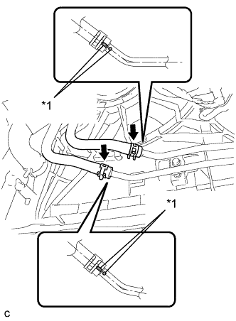
Text in Illustration *1 Matchmark Align the matchmarks as shown in the illustration. Connect the 2 oil cooler hoses.
-
-
CONNECT NO. 2 RADIATOR HOSE
-
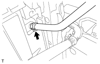
Connect the No. 2 radiator hose.
-
-
CONNECT NO. 1 RADIATOR HOSE
-
Connect the No. 1 radiator hose and hose clamp.
-
-
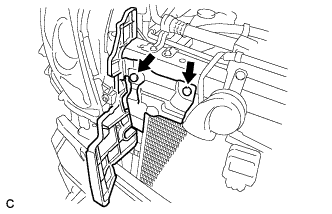
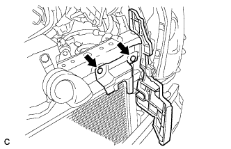
INSTALL HOOD LOCK SUPPORT BRACE SUB-ASSEMBLY
-
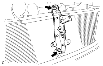
Install the hood lock support brace sub-assembly with the 2 bolts.
- Torque:
- 8.5 N*m { 87 kgf*cm, 75 in.*lbf }
-
w/ smog ventilation sensor:
-
Connect the 4 connectors.
-
Connect the 5 wire harness clamps.
-
-
w/o smog ventilation sensor:
-
Connect the 3 connectors.
-
Connect the 5 wire harness clamps.
-
-
-
INSTALL NO. 2 FRONT BUMPER SIDE SEAL RH
-
Install the No. 2 front bumper side seal RH with the 2 clips.
-
-
INSTALL NO. 2 FRONT BUMPER SIDE SEAL LH
-
Install the No. 2 front bumper side seal LH with the 2 clips.
-
-
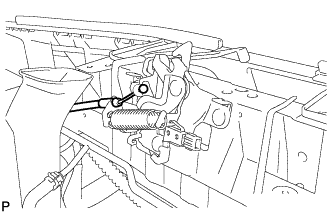
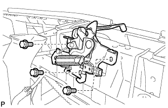
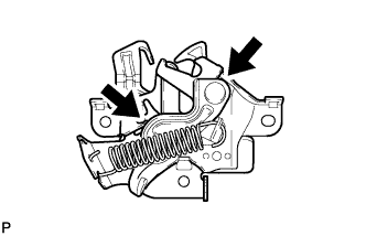
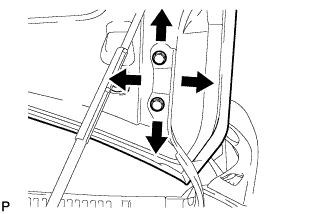
INSTALL HOOD LOCK ASSEMBLY (for LHD)
-
w/o Engine Hood Courtesy Switch:
-
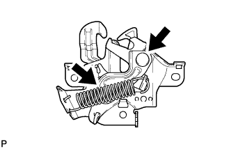
Apply MP grease to the sliding areas of the lock.
-
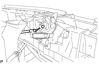
Connect the hood lock control cable.
-
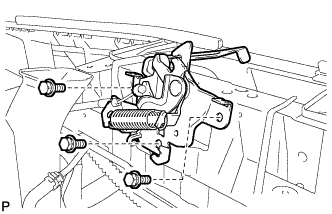
Install the hood lock assembly with the 3 bolts.
- Torque:
- 7.5 N*m { 77 kgf*cm, 66 in.*lbf }
-
-
w/ Engine Hood Courtesy Switch:
-
Apply MP grease to the sliding areas of the lock.
-
Connect the hood lock control cable.
-
Install the hood lock assembly with the 3 bolts.
- Torque:
- 7.5 N*m { 77 kgf*cm, 66 in.*lbf }
-
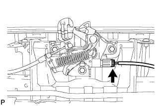
Connect the connector.
-
-
-
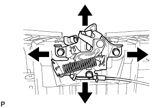
INSTALL HOOD LOCK ASSEMBLY (for RHD)
-
for ALPHARD:
-
Apply MP grease to the sliding areas of the lock.
-
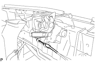
Connect the hood lock control cable.
-
Install the hood lock assembly with the 3 bolts.
- Torque:
- 7.5 N*m { 77 kgf*cm, 66 in.*lbf }
-
-
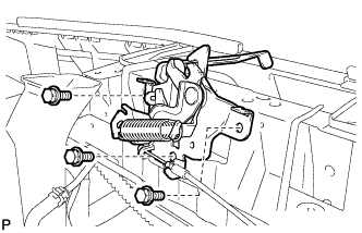
for VELLFIRE:
-
Apply MP grease to the sliding areas of the lock.
-
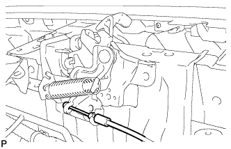
Connect the hood lock control cable.
-
Install the hood lock assembly with the 3 bolts.
- Torque:
- 7.5 N*m { 77 kgf*cm, 66 in.*lbf }
-
-
-
INSPECT HOOD SUB-ASSEMBLY
-
Check that the clearance measurements of areas A through H are within each standard range.
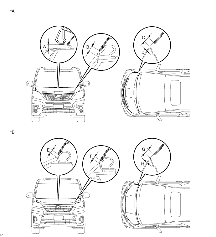
Text in Illustration *A for ALPHARD *B for VELLFIRE Standard Clearance Area Measurement Area Measurement A 5.9 to 9.9 mm (0.232 to 0.390 in.) E 2.2 to 6.2 mm (0.0866 to 0.244 in.) B 3.4 to 7.4 mm (0.134 to 0.291 in.) F 2.3 to 6.3 mm (0.0906 to 0.248 in.) C 2.3 to 5.3 mm (0.0906 to 0.209 in.) G 2.3 to 5.3 mm (0.0906 to 0.209 in.) D -1.4 to 1.6 mm (-0.0551 to 0.0630 in.) H -1.4 to 1.6 mm (-0.0551 to 0.0630 in.)
-
-
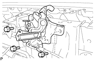
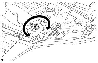
ADJUST HOOD SUB-ASSEMBLY
-
Horizontally and vertically adjust the hood.
-
Loosen the 4 hinge bolts of the hood.
-
Adjust the clearance between the hood and front fender by moving the hood.
-
Tighten the 4 hinge bolts after the adjustment.
- Torque:
- 12 N*m { 122 kgf*cm, 9 ft.*lbf }
-
-
Adjust the height of the front end of the hood using the cushion rubbers.
-
Adjust the cushion rubbers so that the heights of the hood and fender are aligned.
Tech Tips
Raise or lower the front end of the hood by turning the cushion rubbers.
-
-
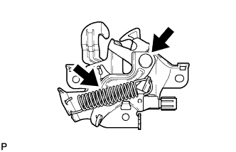
Adjust the hood lock.
-
Loosen the 3 bolts.
-
Tighten the bolts after the adjustment.
- Torque:
- 7.5 N*m { 77 kgf*cm, 66 in.*lbf }
-
Check that the striker can engage with the hood lock smoothly.
-
-
-
INSTALL BATTERY TRAY
-
Install the battery tray.
-
-
INSTALL BATTERY
-
Install the battery and battery insulator.
-
Install the battery clamp with the bolt and nut.
- Torque:
- Bolt
- 46 N*m { 469 kgf*cm, 34 ft.*lbf }
- Nut
- 4.9 N*m { 50 kgf*cm, 43 in.*lbf }
-
Connect the 2 wire harness clamps.
-
Connect the positive (+) cable to the positive (+) battery terminal.
- Torque:
- 5.4 N*m { 55 kgf*cm, 48 in.*lbf }
-
-
INSTALL NO. 1 AIR CLEANER INLET
-
Install the No. 1 air cleaner inlet with the bolt.
- Torque:
- 8.0 N*m { 82 kgf*cm, 71 in.*lbf }
-
-
ADD ENGINE COOLANT
-
Tighten the radiator drain cock plug by hand.
-
Add engine coolant.
Standard capacity 8.6 liters (9.1 US qts, 7.6 Imp. qts) Note
Do not substitute plain water for engine coolant.
Tech Tips
-
TOYOTA vehicles are filled with TOYOTA SLLC at the factory. In order to avoid damage to the engine cooling system and other technical problems, only use TOYOTA SLLC or similar high quality ethylene glycol based non-silicate, non-amine, non-nitrite, non-borate coolant with long-life hybrid organic acid technology (coolant with long-life hybrid organic acid technology is a combination of low phosphates and organic acids).
-
Squeeze the No. 1 radiator hose and No. 2 radiator hose several times by hand, and then check the level of the engine coolant.
If the engine coolant level is low, add engine coolant.
-
-
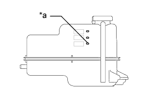
Text in Illustration *a B Line Continue adding engine coolant until it reaches the B line. (*1)
-
Install the reserve tank cap. (*2)
-
Run the engine at about 2000 rpm to warm it up until the thermostat opens. While the thermostat is open, circulate the engine coolant for several minutes. (*3)
CAUTION:
-
Wear protective gloves.
-
Be careful as the No. 1 radiator hose and No. 2 radiator hose are hot.
-
Keep your hands away from the fan and No. 2 fan.
Note
-
If the radiator reserve tank runs out of engine coolant just after the engine is started, stop the engine immediately, wait until the engine coolant has cooled down, and then add engine coolant.
-
Make sure that the radiator reserve tank still has some engine coolant in it.
-
If the coolant temperature gauge indicates an excessive temperature, turn off the engine and let it cool.
-
If there is not enough engine coolant, the engine may overheat or be seriously damaged.
-
-
Stop the engine and wait until the engine coolant cools down. (*4)
-
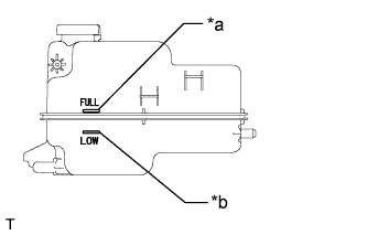
Text in Illustration *a Full Line *b Low Line Check that the engine coolant level is between the full line and low line. (*5)
Tech Tips
-
If the engine coolant level is below the low line, remove the reserve tank cap and repeat steps from (*1) to (*5).
-
If the engine coolant level is above the full line, drain engine coolant so that the engine coolant level is between the full line and low line.
-
-
-
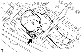
INSPECT FOR COOLANT LEAK
-
Remove the reserve tank cap.
CAUTION:
Do not remove the reserve tank cap while the engine and radiator are still hot. Pressurized, hot engine coolant and steam may be released and cause serious burns.
-
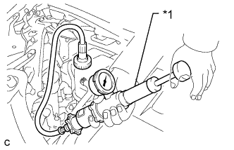
Text in Illustration *1 Radiator Cap Tester Fill the radiator and radiator reserve tank with coolant, and then attach a radiator cap tester.
-
Warm up the engine.
-
Pump the radiator cap tester to 118 kPa (1.2 kgf/cm2, 17 psi), and then check that the pressure does not drop.
If the pressure drops, check the hoses, radiator and water pump for leaks.
If there are no signs of external coolant leaks, check the heater core, cylinder block and head.
-
Reinstall the reserve tank cap.
-
-
INSTALL FRONT BUMPER ASSEMBLY
-
INSTALL NO. 1 ENGINE UNDER COVER
-
CONNECT CABLE TO NEGATIVE BATTERY TERMINAL
Note
When disconnecting the cable, some systems need to be initialized after the cable is reconnected Click here.