WATER PUMP REMOVAL

-
DISCONNECT CABLE FROM NEGATIVE BATTERY TERMINAL
Note
When disconnecting the cable, some systems need to be initialized after the cable is reconnected Click here.
-
REMOVE FRONT WHEEL RH
-
REMOVE NO. 1 ENGINE UNDER COVER
-
REMOVE REAR ENGINE UNDER COVER RH
-
REMOVE RADIATOR COVER SUB-ASSEMBLY
-
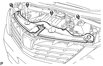
Using a clip remover, remove the 4 clips and radiator cover sub-assembly.
-
-
DRAIN ENGINE COOLANT
-
Loosen the radiator drain cock plug and drain the coolant.
CAUTION:
Do not remove the reserve tank cap, cylinder block drain cock plug and radiator drain cock plug while the engine or radiator are still hot. Pressurized, hot engine coolant and steam may be released and cause serious burns.
Tech Tips
Collect the coolant in a container and dispose of it according to the local regulations.
-
Remove the reserve tank cap.
-
Loosen the cylinder block drain cock plug. (except TMC Made)
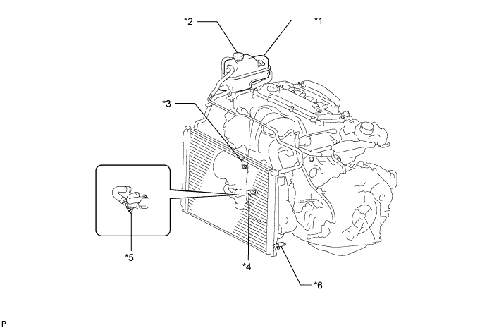
Text in Illustration *1 Radiator Reserve Tank *2 Reserve Tank Cap *3 Cylinder Block Drain Cock Plug (except TMC Made) *4 Cylinder Block Drain Cock Plug (for TMC Made w/o Oil Cooler) *5 Water Drain Cock Plug (for TMC Made w/ Oil Cooler) *6 Radiator Drain Cock Plug -
Loosen the cylinder block drain cock plug. (for TMC Made w/o Oil Cooler)
-
Loosen the water drain cock plug. (for TMC Made w/ Oil Cooler)
-
-
REMOVE RADIATOR RESERVE TANK ASSEMBLY
-
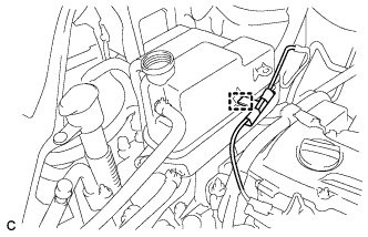
Disconnect the wire clamp.
-
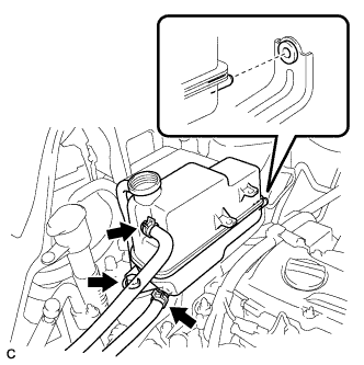
Disconnect the No. 1 and No. 2 water by-pass hoses.
-
Remove the bolt and radiator reserve tank assembly.
-
-
REMOVE RADIATOR RESERVE TANK BRACKET
-
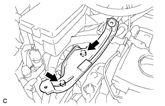
Remove the 2 bolts and radiator reserve tank bracket.
-
-
REMOVE V-RIBBED BELT
-
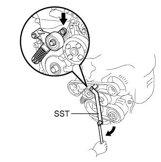
Using SST, slowly turn the V-ribbed belt tensioner clockwise.
- SST
- 09216-42010 ( 09216-04010 )
-
Remove the V-ribbed belt from each pulley and slowly return the tensioner.
Note
-
Make sure that SST and other tools are set to the tensioner securely.
-
When compressing the V-ribbed belt tensioner, slowly turn the tensioner.
-
Be careful not to pinch your fingers between the parts.
-
-
-
REMOVE GENERATOR ASSEMBLY
-
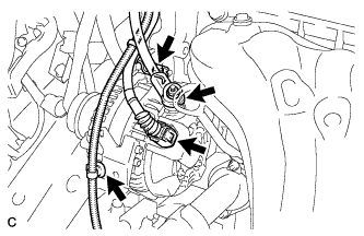
Disconnect the generator connector from the generator assembly.
-
Open the terminal cap.
-
Remove the nut and disconnect the wire harness from terminal B.
-
Remove the bolt and wire harness clamp bracket.
-
Disconnect the wire harness clamp.
-
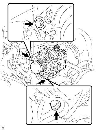
Remove the 2 bolts.
-
-
REMOVE ENGINE MOUNTING INSULATOR SUB-ASSEMBLY RH
-
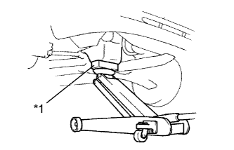
Text in Illustration *1 Wooden Block Place a wooden block on a jack underneath the engine.
-
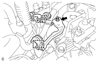
Disconnect the 4 clamps.
-
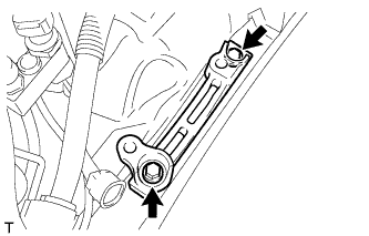
Remove the nut and cooler pipe bracket.
-
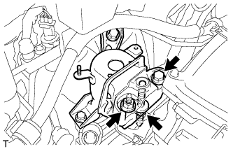
Remove the bolt and 2 nuts, then separate the engine mounting insulator sub-assembly RH from the engine mounting bracket RH.
-
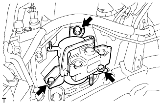
Remove the 3 bolts and engine mounting insulator sub-assembly RH.
-
-
REMOVE ENGINE MOUNTING SPACER
-
Remove the 2 bolts and engine mounting spacer.
-
-
REMOVE WATER PUMP PULLEY
-
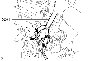
Using SST, remove the 4 bolts and water pump pulley.
- SST
- 09960-10010 ( 09962-01000, 09963-00700 )
-
-
REMOVE WATER PUMP ASSEMBLY (for TMC Made)
-
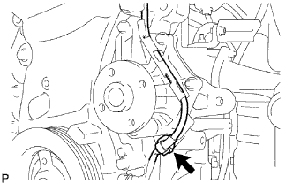
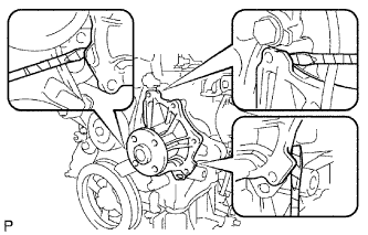
Remove the clamp of the crankshaft position sensor from the water pump.
-
Disconnect the wire of the crankshaft position sensor from the clamp bracket.
-
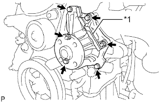
Text in Illustration *1 Clamp Bracket Remove the 4 bolts, 2 nuts and clamp bracket.
-
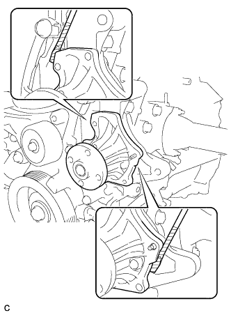
Using a screwdriver, pry between the water pump and cylinder block, and then remove the water pump.
Tech Tips
Tape the screwdriver tip before use.
Note
Be careful not to damage the contact surfaces of the water pump and cylinder block.
-
-
REMOVE WATER PUMP ASSEMBLY (except TMC Made)
-
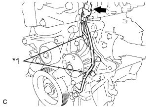
Text in Illustration *1 Clamp Bracket Disconnect the connector of the crankshaft position sensor.
-
Disconnect the wire of the crankshaft position sensor from the clamp brackets.
-
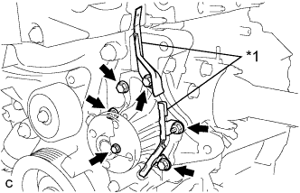
Text in Illustration *1 Clamp Bracket Remove the 4 bolts, 2 nuts and 2 clamp brackets.
-
Using a screwdriver, pry between the water pump and cylinder block, and then remove the water pump.
Tech Tips
Tape the screwdriver tip before use.
Note
Be careful not to damage the contact surfaces of the water pump and cylinder block.
-