INTAKE MANIFOLD INSTALLATION

-
INSTALL INTAKE MANIFOLD
-
Set 2 new intake manifold to head gaskets on each cylinder head.
Note
-
Align the port holes of the gaskets and cylinder head.
-
Make sure that the gaskets are installed in the correct direction.
-
-
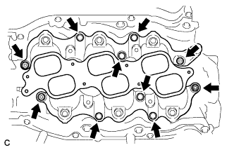
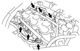
Set the intake manifold on the cylinder head.
-
Install and tighten the 6 bolts and 4 nuts uniformly in several steps.
- Torque:
- 21 N*m { 214 kgf*cm, 15 ft.*lbf }
-
-
INSTALL FUEL INJECTOR ASSEMBLY
-
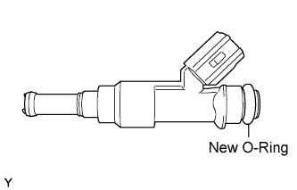
Apply a light coat of spindle oil or gasoline to new O-rings, and install them to each injector.
-
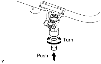
Apply a light coat of spindle oil or gasoline where the fuel delivery pipe contacts each O-ring.
-
Push and twist each fuel injector to install them into the fuel delivery pipe.
-
Position each fuel injector connector outward.
Note
-
Be careful not to twist the O-rings.
-
After installing a fuel injector, check that it turns smoothly. If not, reinstall it with a new O-ring.
-
-
Install 6 new injector vibration insulators to the intake manifold.
-
Place the fuel delivery pipe with the 6 fuel injectors in position on the intake manifold.
Note
Be careful not to drop the fuel injectors when installing the fuel delivery pipe.
-
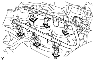
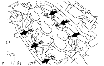
Temporarily install the 5 bolts which are used to hold the fuel delivery pipe to the intake manifold.
Note
After installing the fuel injectors, check that they turn smoothly. If not, reinstall the injectors with new O-rings.
-
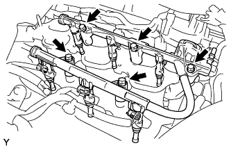
Tighten the 5 bolts which are used to hold the fuel delivery pipe to the intake manifold.
- Torque:
- 21 N*m { 214 kgf*cm, 15 ft.*lbf }
-
Connect the 6 fuel injector connectors.
-
-
CONNECT FUEL TUBE SUB-ASSEMBLY
-
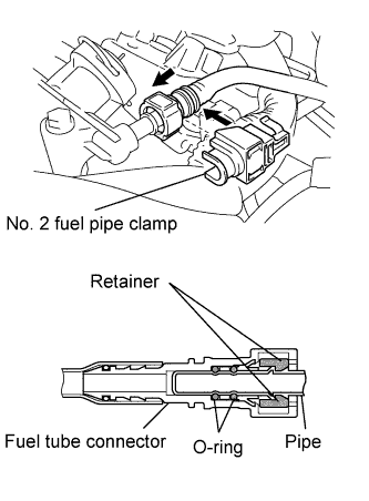
Push in the tube connector onto the pipe until the tube connector makes a "click" sound.
Note
-
Before connecting the tube, make sure that it is not damaged. Make sure that there is no dirt present on the connecting surfaces.
-
After connecting, check that the fuel tube connector and the pipe are securely connected by pulling on them.
-
-
Install the No. 2 fuel pipe clamp.
-
-
INSTALL NO. 2 ENGINE MOUNTING STAY RH
-
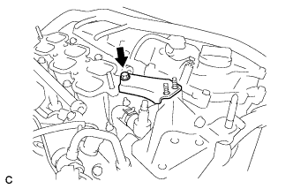
Install the No. 2 mounting stay RH with the bolt.
- Torque:
- 21 N*m { 214 kgf*cm, 15 ft.*lbf }
-
-
INSTALL INTAKE AIR SURGE TANK ASSEMBLY
NOTICE DO NOT apply oil to the bolts listed below: Tightening Part Surge Tank and Intake Manifold No. 1 Surge Tank Stay and Surge Tank Throttle Body Bracket and Surge Tank
-
Install 3 new air surge tank to intake manifold gaskets to the intake air surge tank.
-

Using a 5 mm hexagon socket wrench, install the intake air surge tank assembly with the 4 bolts and 2 nuts.
- Torque:
- Bolt
- 18 N*m { 184 kgf*cm, 13 ft.*lbf }
- Nut
- 16 N*m { 163 kgf*cm, 12 ft.*lbf }
-
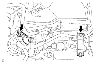
Install the throttle body bracket and No. 1 surge tank stay with the 2 bolts.
- Torque:
- 21 N*m { 214 kgf*cm, 15 ft.*lbf }
-
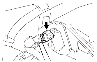
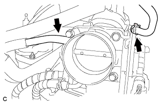
Connect the connector to the intake air control valve assembly.
-
Connect the 2 water by-pass hoses to the throttle body assembly.
-
Connect the fuel vapor feed hose to the intake air surge tank assembly.
-
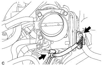
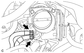
Connect the throttle body assembly connector and wire harness clamp to the throttle body assembly.
-
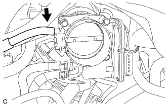
Connect the ventilation hose.
-
Connect the union to connector tube hose.
-
-
INSTALL AIR CLEANER CAP SUB-ASSEMBLY
-
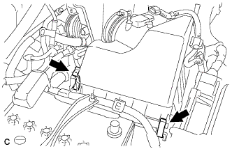
Install the air cleaner cap sub-assembly to the air cleaner case with the 2 clamps.
-
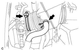
Connect the air cleaner hose to the throttle body with the hose clamp.
-
Connect the ventilation hose.
-
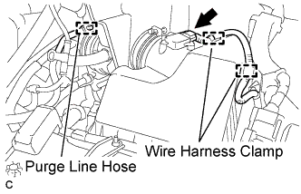
Connect the purge line hose.
-
Connect the 2 wire harness clamps and mass air flow meter connector.
-
-
CONNECT CABLE TO NEGATIVE BATTERY TERMINAL
Note
When disconnecting the cable, some systems need to be initialized after the cable is reconnected Click here.
-
INSTALL RADIATOR COVER SUB-ASSEMBLY (for ALPHARD)
-
Install the radiator cover sub-assembly with the 4 clips.
-
-
INSTALL RADIATOR COVER SUB-ASSEMBLY (for VELLFIRE)
-
Install the radiator cover sub-assembly with the 4 clips.
-
-
ADD ENGINE COOLANT
-
Tighten the radiator drain cock plug by hand.
-
Tighten the 2 cylinder block drain cock plugs.
- Torque:
- 13 N*m { 130 kgf*cm, 9 ft.*lbf }
-
Remove the reserve tank cap. (*1)
-
Loosen the air drain cock plug on the water inlet housing.
-
Add TOYOTA Super Long Life Coolant (SLLC).
Standard capacity 10.6 liters (11.2 US qts, 9.3 Imp. qts) Note
Never use water as a substitute for engine coolant.
Tech Tips
-
TOYOTA vehicles are filled with TOYOTA SLLC at the factory. In order to avoid damage to the engine cooling system and other technical problems, only use TOYOTA SLLC or similar high quality ethylene glycol based non-silicate, non-amine, non-nitrite, non-borate coolant with long-life hybrid organic acid technology (coolant with long-life hybrid organic acid technology consists of a combination of low phosphates and organic acids).
-
Squeeze the No. 1 and No. 2 radiator hoses several times. If the coolant level at the water inlet opening drops, add TOYOTA SLLC.
-
-
Add TOYOTA SLLC to the reserve tank until coolant overflows from the air drain cock plug hole. Then tighten the air drain cock plug on the water inlet housing.
- Torque:
- 13 N*m { 130 kgf*cm, 9 ft.*lbf }
-
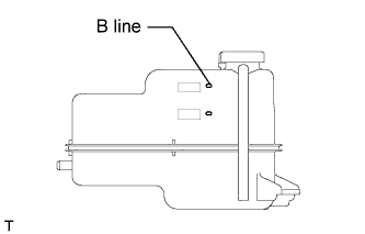
Continue adding TOYOTA SLLC until it reaches the B line. (*2)
-
Install the reserve tank cap. (*3)
-
Run the engine at about 2000 rpm to warm it up until the thermostat opens. While the thermostat is open, circulate the coolant for several minutes. (*4)
CAUTION:
-
When push the radiator hoses, wear protective gloves.
-
Be careful as the radiator hoses, engine and radiator are hot.
-
Keep your hands away from the radiator fans.
Note
-
If the radiator reserve tank runs out of coolant just after the engine is started, stop the engine immediately, wait until the coolant has cooled down, and then add coolant.
-
Make sure that the reserve tank still has some coolant in it.
-
If the coolant temperature gauge indicates an excessive temperature, turn off the engine and let it cool.
-
If there is not enough coolant, the engine may overheat or be seriously damaged.
Tech Tips
-
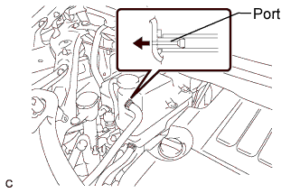
If coolant comes out from the bypass hose port connected to the reserve tank, the thermostat has been opened.
-
After the thermostat has opened, idle the engine until the coolant in the reserve tank goes from being cloudy to a clear red.
-
-
Stop the engine and wait until the coolant cools down. (*5)
-
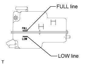
Check that the coolant level is between the FULL and LOW lines. (*6)
Tech Tips
-
If the coolant level is below the LOW line, repeat steps from (*1) to (*6).
-
If the coolant level is above the FULL line, drain coolant so that the coolant level is between the FULL and LOW lines.
-
-
-
INSPECT FOR COOLANT LEAK
-
Remove the radiator reservoir cap.
CAUTION:
Do not remove the radiator reservoir cap while the engine and radiator are still hot. Pressurized, hot engine coolant and steam may be released and cause serious burns.
-
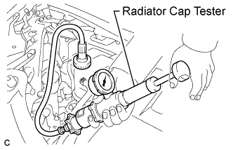
Fill the radiator and reservoir with coolant, and then attach a radiator cap tester.
-
Warm up the engine.
-
Pump the radiator cap tester to 118 kPa (1.2 kgf/cm2, 17 psi), and then check that the pressure does not drop.
If the pressure drops, check the hoses, radiator and water pump for leaks.
If there are no signs of external coolant leaks, check the heater core, cylinder block and head.
-
Reinstall the radiator reservoir cap.
-
-
INSPECT FOR FUEL LEAK
-
Check that there are no fuel leaks from the fuel system after doing any maintenance or repairs Click here.
-
-
INSTALL NO. 1 ENGINE UNDER COVER
-
INSTALL V-BANK COVER SUB-ASSEMBLY
-
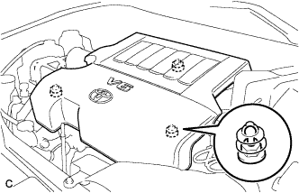
Fit the 3 retainers and install the V-bank cover sub-assembly.
-
-
INSTALL COWL TOP PANEL OUTER SUB-ASSEMBLY
-
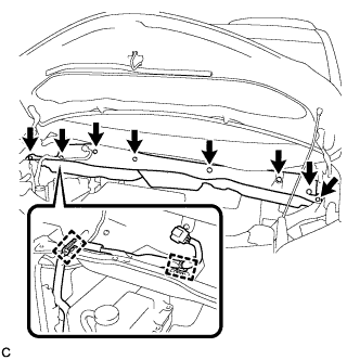
Install the outer cowl top panel with the 8 bolts.
- Torque:
- 8.8 N*m { 90 kgf*cm, 78 in.*lbf }
-
Connect the 2 clamps to the outer cowl top panel.
-
Remove the protective tape.
-
-
INSTALL RESERVOIR BRACKET
-
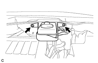
Install the brake master cylinder reservoir with bracket to the outer cowl top panel with the 2 nuts.
- Torque:
- 6.5 N*m { 66 kgf*cm, 58 in.*lbf }
-
-
INSTALL WINDSHIELD WIPER MOTOR AND LINK ASSEMBLY
-
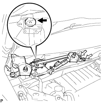
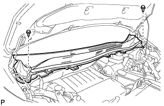
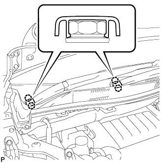
Install the windshield wiper motor and link assembly with the 3 bolts as shown in the illustration.
- Torque:
- 5.5 N*m { 56 kgf*cm, 49 in.*lbf }
-
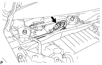
Connect the connector.
-
-
INSTALL COWL TOP VENTILATOR LOUVER SUB-ASSEMBLY
-
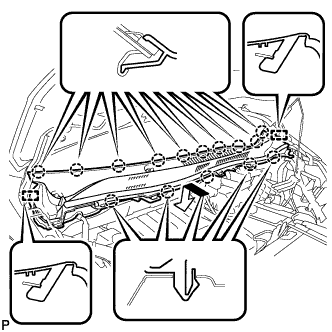
Engage the 15 claws and 2 guides to install the cowl top ventilator louver sub-assembly as shown in the illustration.
-
Install the 2 clips.
-
-
INSTALL WINDSHIELD WIPER ARM AND BLADE ASSEMBLY RH
-
Operate the wiper and stop the windshield wiper motor at the automatic stop position.
-
When reusing the front wiper arm and blade assembly RH:
-
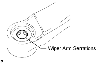
Clean the wiper arm serrations.
-
-
When reusing the windshield wiper link assembly:
-
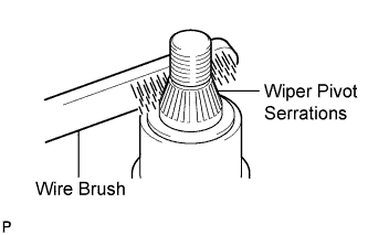
Clean the wiper pivot serrations with a wire brush.
-
-
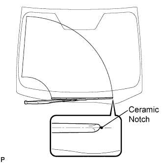
Install the front wiper arm and blade assembly RH with the nut to the position shown in the illustration.
- Torque:
- 24 N*m { 245 kgf*cm, 18 ft.*lbf }
-
-
INSTALL WINDSHIELD WIPER ARM AND BLADE ASSEMBLY LH
-
When reusing the front wiper arm and blade assembly LH:
-
Clean the wiper arm serrations.
-
-
When reusing the windshield wiper link assembly:
-
Clean the wiper pivot serrations with a wire brush.
-
-
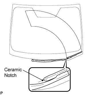
Install the front wiper arm and blade assembly LH with the nut to the position shown in the illustration.
- Torque:
- 24 N*m { 245 kgf*cm, 18 ft.*lbf }
-
Operate the front wipers while spraying washer fluid onto the windshield. Make sure that the front wipers function properly and the wipers do not come into contact with the vehicle body.
-
-
INSTALL WINDSHIELD WIPER ARM COVER
-
Engage the 2 claws to install the 2 windshield wiper arm covers.
-