INTAKE MANIFOLD REMOVAL

-
DISCHARGE FUEL SYSTEM PRESSURE
Tech Tips
-
DISCONNECT CABLE FROM NEGATIVE BATTERY TERMINAL
Note
When disconnecting the cable, some systems need to be initialized after the cable is reconnected Click here.
-
REMOVE RADIATOR COVER SUB-ASSEMBLY (for ALPHARD)
-
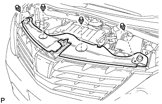
Using a clip remover, remove the 4 clips and radiator cover sub-assembly.
-
-
REMOVE RADIATOR COVER SUB-ASSEMBLY (for VELLFIRE)
-
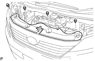
Using a clip remover, remove the 4 clips and radiator cover sub-assembly.
-
-
REMOVE NO. 1 ENGINE UNDER COVER
-
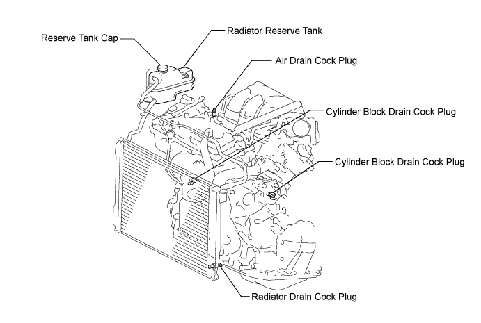
DRAIN ENGINE COOLANT
-
Loosen the radiator drain cock plug and drain the coolant.
CAUTION:
Do not remove the reserve tank cap, cylinder block drain cock plugs and radiator drain cock plug while the engine and radiator are still hot. Pressurized, hot engine coolant and steam may be released and cause serious burns.
Tech Tips
Collect the coolant in a container and dispose of it according to the regulations in your area.
-
Remove the reserve tank cap.
-
Loosen the 2 cylinder block drain cock plugs.
-
-
REMOVE WINDSHIELD WIPER ARM COVER
-
Using a screwdriver, disengage the 2 claws and remove the 2 windshield wiper arm covers.
Tech Tips
Tape the screwdriver tip before use.
-
-
REMOVE WINDSHIELD WIPER ARM AND BLADE ASSEMBLY RH
-
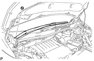
Remove the nut and the front wiper arm and blade assembly RH.
-
-
REMOVE WINDSHIELD WIPER ARM AND BLADE ASSEMBLY LH
-
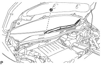
Remove the nut and the front wiper arm and blade assembly LH.
-
-
REMOVE COWL TOP VENTILATOR LOUVER SUB-ASSEMBLY
-
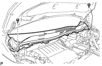
Remove the 2 clips.
-
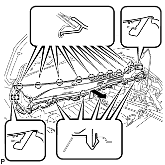
Disengage the 15 claws and 2 guides, and remove the cowl top ventilator louver sub-assembly as shown in the illustration.
-
-
REMOVE WINDSHIELD WIPER MOTOR AND LINK ASSEMBLY
-
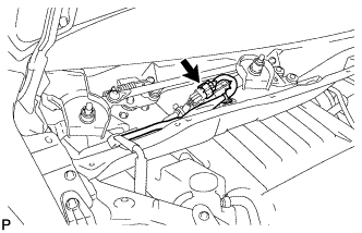
Disconnect the connector.
-
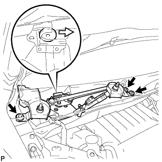
Remove the 3 bolts and the windshield wiper motor and link assembly as shown in the illustration.
-
-
SEPARATE RESERVOIR BRACKET
-
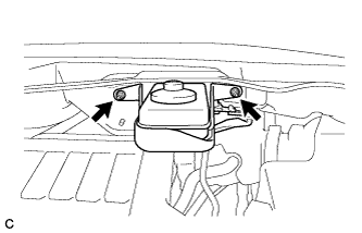
Remove the 2 nuts and separate the brake master cylinder reservoir with bracket from the outer cowl top panel.
-
-
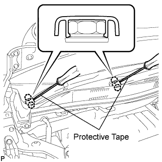
REMOVE COWL TOP PANEL OUTER SUB-ASSEMBLY
-
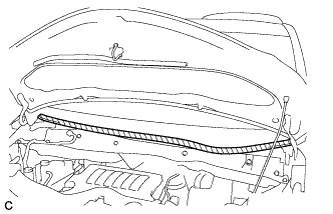
Apply protective tape as shown in the illustration.
Text in Illustration 
Protective Tape -
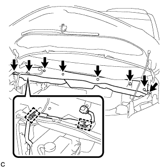
Disconnect the 2 clamps from the outer cowl top panel.
-
Remove the 8 bolts.
-
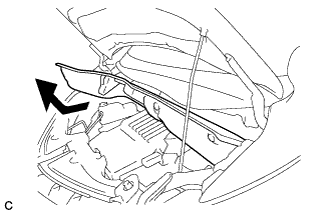
Remove the outer cowl top panel as shown in the illustration.
-
-
REMOVE V-BANK COVER SUB-ASSEMBLY
-
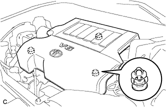
Hold the front of the V-bank cover sub-assembly and raise it to disengage the 2 clips on the front of the cover. Continue to raise the cover to disengage the clip on the rear of the cover and remove the V-bank cover sub-assembly.
Note
Attempting to disengage both front and rear clips at the same time may cause the cover to break.
-
-
REMOVE AIR CLEANER CAP SUB-ASSEMBLY
-
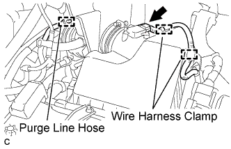
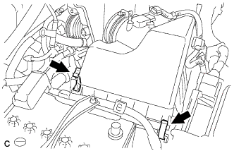
Separate the mass air flow meter connector and 2 wire harness clamps.
-
Separate the purge line hose.
-
Separate the ventilation hose.
-
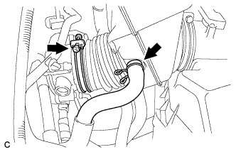
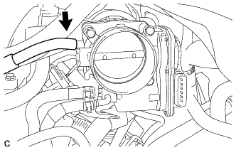
Loosen the hose clamp and separate the air cleaner hose from the throttle body.
-
Release the 2 clamps and remove the air cleaner cap sub-assembly.
-
-
REMOVE INTAKE AIR SURGE TANK ASSEMBLY
-
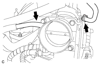
Disconnect the union to connector tube hose.
-
Disconnect the ventilation hose.
-
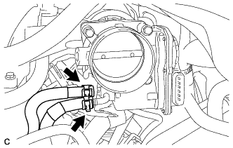
Disconnect the throttle body assembly connector and wire harness clamp.
-
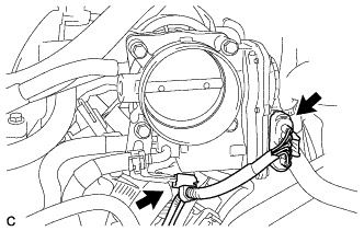
Disconnect the fuel vapor feed hose.
-
Disconnect the 2 water by-pass hoses.
-
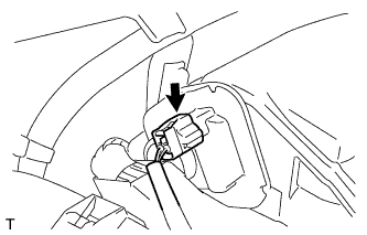
Disconnect the connector from the intake air control valve assembly.
-
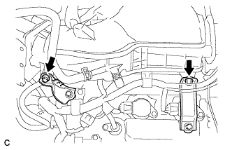
Remove the bolt and separate the No. 1 surge tank stay from the intake air surge tank assembly.
-
Remove the bolt and separate the throttle body bracket from the intake air surge tank assembly.
-

Remove the 2 nuts from the intake air surge tank assembly.
-
Using a 5 mm socket hexagon wrench, remove the 4 bolts.
-
Remove the intake air surge tank assembly and 3 air surge tank to intake manifold gaskets.
-
-
REMOVE NO. 2 ENGINE MOUNTING STAY RH
-
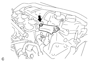
Remove the bolt and No. 2 engine mounting stay RH.
-
-
DISCONNECT FUEL TUBE SUB-ASSEMBLY
-
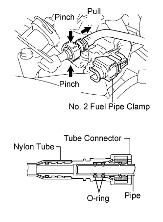
Remove the No. 2 fuel pipe clamp.
-
Pinch the tube connector and pull out the fuel pipe.
Note
-
Check that there is no dirt or other foreign matter around the connector when disconnecting it. Clean the connector as necessary.
-
It is necessary to prevent dirt or foreign matter from entering the quick connector. If dirt or foreign matter gets in the connector, the O-rings may not seal properly.
-
Only disconnect the quick connector by hand.
-
Do not bend, kink or twist the nylon tubes.
-
Protect the connector by covering it with a plastic bag.
-
If the pipe and the connector are stuck, carefully try wiggling or pushing and pulling on the connector to release it. Pull the connector off the pipe carefully.
-
-
-
REMOVE FUEL INJECTOR ASSEMBLY
-
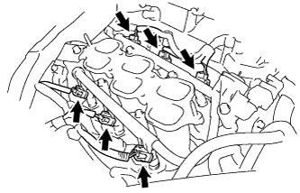
Disconnect the 6 fuel injector connectors.
-
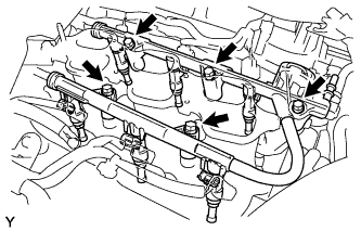
Remove the 5 bolts and fuel delivery pipe sub-assembly together with the 6 fuel injectors.
Note
Be careful not to drop the fuel injectors when removing the fuel delivery pipe.
-
Remove the 6 injector vibration insulators from the intake manifold.
-
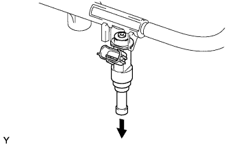
Pull out the fuel injectors from the fuel delivery pipe.
Note
If the injectors are to be reused, reinstall them to the same cylinder they came from.
-
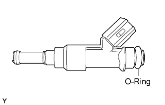
Remove the 6 O-rings from the injectors.
-
-
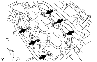
REMOVE INTAKE MANIFOLD
-
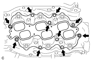
Remove the 6 bolts, 4 nuts, intake manifold and 2 intake manifold to head gaskets.
-