WATER PUMP INSTALLATION

-
INSTALL WATER PUMP ASSEMBLY (for TMC Made)
-
Remove any old seal packing material from the contact surfaces.
-
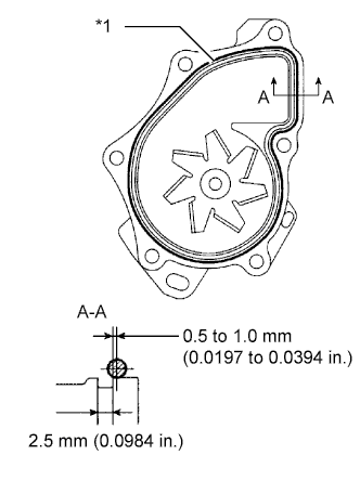
Text in Illustration *1 Seal Packing Apply a continuous line of seal packing as shown in the illustration.
Seal packing Toyota Genuine Seal Packing 1282B, Three Bond 1282B or equivalent Standard seal diameter 2.2 to 2.5 mm (0.0866 to 0.0984 in.) Note
-
Remove any oil from the contact surfaces.
-
The parts must be set within 3 minutes after applying seal packing. Otherwise, the material must be removed and reapplied.
-
-
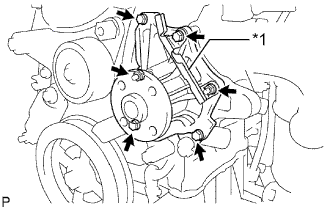
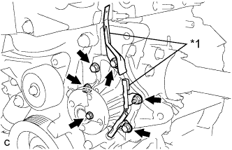
Text in Illustration *1 Clamp Bracket Install the water pump assembly and clamp bracket with the 4 bolts and 2 nuts.
- Torque:
- 9.0 N*m { 92 kgf*cm, 80 in.*lbf }
-
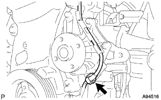
Install the wire of the crankshaft position sensor onto the clamp bracket.
-
Install the clamp of the crankshaft position sensor onto the water pump.
-
-
INSTALL WATER PUMP ASSEMBLY (except TMC Made)
-
Remove any old seal packing material from the contact surfaces.
-
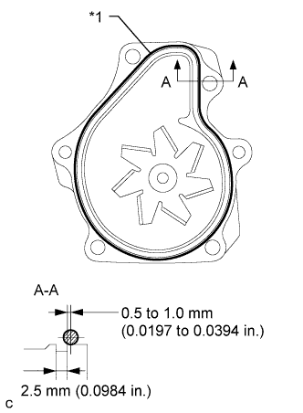
Text in Illustration *1 Seal Packing Apply a continuous line of seal packing as shown in the illustration.
Seal packing Toyota Genuine Seal Packing 1282B, Three Bond 1282B or equivalent Standard seal diameter 2.2 to 2.5 mm (0.0866 to 0.0984 in.) Note
-
Remove any oil from the contact surfaces.
-
The parts must be set within 3 minutes after applying seal packing. Otherwise, the material must be removed and reapplied.
-
-
Text in Illustration *1 Clamp Bracket Install the water pump assembly and 2 clamp brackets with the 4 bolts and 2 nuts.
- Torque:
- 9.0 N*m { 92 kgf*cm, 80 in.*lbf }
-
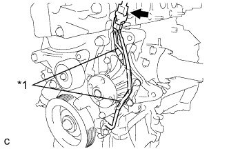
Install the wire of the crankshaft position sensor onto the clamp bracket.
-
Connect the connector of the crankshaft position sensor.
-
-
INSTALL WATER PUMP PULLEY
-
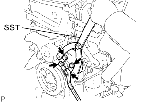
Using SST, install the water pump pulley with the 4 bolts.
- SST
- 09960-10010 ( 09962-01000, 09963-00700 )
- Torque:
- 26 N*m { 265 kgf*cm, 19 ft.*lbf }
-
-
INSTALL ENGINE MOUNTING SPACER
-
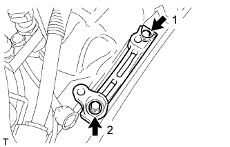
Temporarily tighten the engine mounting spacer with the 2 bolts.
-
Uniformly tighten the 2 bolts in the sequence shown in the illustration.
- Torque:
- 95 N*m { 969 kgf*cm, 70 ft.*lbf }
-
-
INSTALL ENGINE MOUNTING INSULATOR SUB-ASSEMBLY RH
-
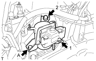
Temporarily install the engine mounting insulator sub-assembly RH with the bolt (A).
-
Uniformly tighten the 2 bolts in the sequence shown in the illustration.
- Torque:
- 95 N*m { 969 kgf*cm, 70 ft.*lbf }
-
Fully tighten the bolt (A).
- Torque:
- 95 N*m { 969 kgf*cm, 70 ft.*lbf }
-
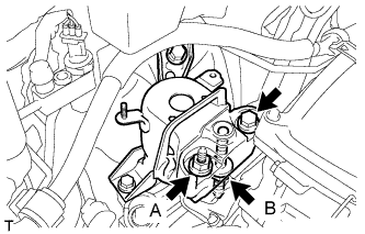
Install the engine mounting insulator sub-assembly RH with the bolt and 2 nuts.
- Torque:
- Bolt
- 95 N*m { 969 kgf*cm, 70 ft.*lbf }
- Nut A
- 95 N*m { 969 kgf*cm, 70 ft.*lbf }
- Nut B
- 52 N*m { 530 kgf*cm, 38 ft.*lbf }
-
Install the cooler pipe bracket with the nut.
- Torque:
- 9.8 N*m { 100 kgf*cm, 87 in.*lbf }
-
Connect the 4 clamps to the cooler pipe bracket.
-
-
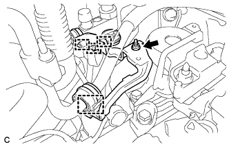
INSTALL GENERATOR ASSEMBLY
-
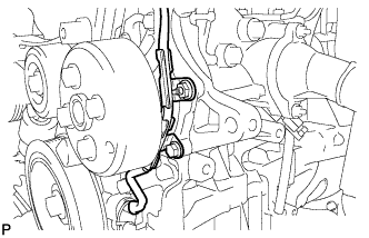
Confirm that the wire harness of the crankshaft position sensor is secured to the wire harness clamp bracket through the back of the rib of the timing chain cover.
-
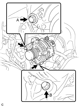
Install the generator assembly with the 2 bolts.
- Torque:
- Bolt A
- 52 N*m { 530 kgf*cm, 38 ft.*lbf }
- Bolt B
- 21 N*m { 214 kgf*cm, 15 ft.*lbf }
-
Install the generator wire to terminal B with the nut.
- Torque:
- 9.8 N*m { 100 kgf*cm, 88 in.*lbf }
-
Install the clamp bracket with the bolt.
- Torque:
- 7.7 N*m { 79 kgf*cm, 68 in.*lbf }
-
Attach the clamp and connect the generator connector to the generator.
-
-
INSTALL V-RIBBED BELT
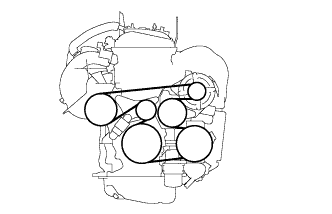
Tech Tips
The illustration shows the V-ribbed belt layout.
-
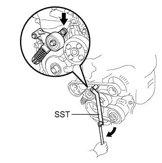
Using SST, slowly turn the V-ribbed belt tensioner clockwise and install the V-ribbed belt.
- SST
- 09216-42010 ( 09216-04010 )
Note
-
Make sure that SST and other tools are set to the tensioner securely.
-
When compressing the V-ribbed belt tensioner, slowly turn the tensioner.
-
-
INSTALL RADIATOR RESERVE TANK BRACKET
-
Install the radiator reserve tank bracket with the 2 bolts.
- Torque:
- 12 N*m { 122 kgf*cm, 9 ft.*lbf }
-
-
INSTALL RADIATOR RESERVE TANK ASSEMBLY
-
Install the radiator reserve tank assembly to the radiator reserve tank bracket.
- Torque:
- 12 N*m { 122 kgf*cm, 9 ft.*lbf }
-
Connect the No. 1 and No. 2 water by-pass hoses.
-
Connect the wire harness clamp to the radiator reserve tank assembly.
-
-
CONNECT CABLE TO NEGATIVE BATTERY TERMINAL
Note
When disconnecting the cable, some systems need to be initialized after the cable is reconnected Click here.
-
ADD ENGINE COOLANT
-
Tighten the radiator drain cock plug by hand.
-
Tighten the cylinder block drain cock plug.
- Torque:
- 13 N*m { 130 kgf*cm, 9 ft.*lbf }
-
Remove the reserve tank cap. (*1)
-
Add TOYOTA Super Long Life Coolant (SLLC).
Standard capacity 8.6 liters (9.1 US qts, 7.6 Imp. qts) Note
Never use water as a substitute for engine coolant.
Tech Tips
-
TOYOTA vehicles are filled with TOYOTA SLLC at the factory. In order to avoid damage to the engine cooling system and other technical problems, only use TOYOTA SLLC or similar high quality ethylene glycol based non-silicate, non-amine, non-nitrite, non-borate coolant with long-life hybrid organic acid technology (coolant with long-life hybrid organic acid technology is a combination of low phosphates and organic acids).
-
Squeeze the No. 1 and No. 2 radiator hoses several times. If the coolant level at the water inlet opening drops, add TOYOTA SLLC.
-
-
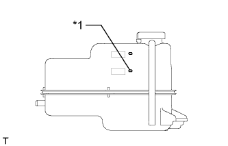
Text in Illustration *1 B Line Continue adding TOYOTA SLLC until it reaches the B line. (*2)
-
Install the reserve tank cap. (*3)
-
Run the engine at about 2000 rpm to warm it up until the thermostat opens. While the thermostat is open, circulate the coolant for several minutes. (*4)
CAUTION:
-
When pushing the radiator hoses, wear protective gloves.
-
Be careful as the radiator hoses, engine and radiator are hot.
-
Keep your hands away from the radiator fans.
Note
-
If the radiator reserve tank runs out of coolant just after the engine is started, stop the engine immediately, wait until the coolant has cooled down, and then add coolant.
-
Make sure that the reserve tank still has some coolant in it.
-
If the coolant temperature gauge indicates an excessive temperature, turn off the engine and let it cool.
-
If there is not enough coolant, the engine may overheat or be seriously damaged.
-
-
Stop the engine and wait until the coolant cools down. (*5)
-
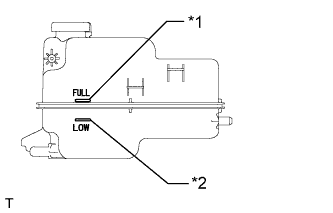
Text in Illustration *1 Full Line *2 Low Line Check that the coolant level is between the full and low lines. (*6)
Tech Tips
-
If the coolant level is below the low line, repeat steps from (*1) to (*6).
-
If the coolant level is above the full line, drain coolant so that the coolant level is between the full and low lines.
-
-
-
INSPECT FOR COOLANT LEAK
-
Remove the reserve tank cap.
CAUTION:
Do not remove the reserve tank cap while the engine and radiator are still hot. Pressurized, hot engine coolant and steam may be released and cause serious burns.
-
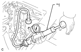
Text in Illustration *1 Radiator Cap Tester Fill the radiator and radiator reserve tank with coolant, and then attach a radiator cap tester.
-
Warm up the engine.
-
Pump the radiator cap tester to 118 kPa (1.2 kgf/cm2, 17 psi), and then check that the pressure does not drop.
If the pressure drops, check the hoses, radiator and water pump for leaks.
If there are no signs of external coolant leaks, check the heater core, cylinder block and head.
-
Reinstall the reserve tank cap.
-
-
INSTALL RADIATOR COVER SUB-ASSEMBLY
-
Install the radiator cover sub-assembly with the 4 clips.
-
-
INSTALL REAR ENGINE UNDER COVER RH
-
INSTALL NO. 1 ENGINE UNDER COVER
-
INSTALL FRONT WHEEL RH