FUEL PUMP INSTALLATION

-
INSTALL FUEL SUCTION TUBE ASSEMBLY WITH PUMP AND GAUGE
-
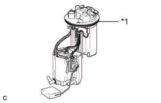
Text in Illustration *1 Gasket Install a new gasket onto the fuel pump.
-
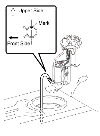
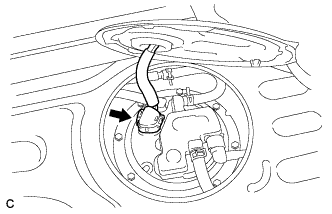
Connect the fuel hose and install the fuel pump into the fuel tank.
Note
-
When connecting the fuel hose, make sure that the fuel hose mark faces upward and the grip part of the clamp faces the front of the vehicle.
-
Be careful not to bend the arm of the fuel sender gauge.
-
When connecting the fuel hose, do not forcibly pull the hose.
-
-
-
CONNECT NO. 2 FUEL EVAPORATION TUBE SUB-ASSEMBLY
-
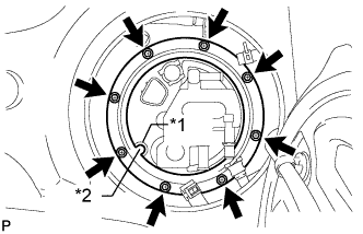
Text in Illustration *1 Groove *2 Protrusion Temporarily install the set plate with the 8 bolts.
Tech Tips
Align the protrusion of the set plate with the groove of the fuel pump.
-
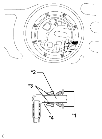
Text in Illustration *1 Retainer *2 Pipe *3 O-ring *4 Fuel Tube Connector Connect the tube to the fuel tube assembly.
Note
-
Before installing the tube, make sure that it is not damaged. Make sure that there is no foreign matter present on the connecting surfaces.
-
After connecting, check if the pipe and the connector are securely connected by pulling on them.
-
-
-
INSTALL FUEL TANK VENT TUBE SET PLATE
-
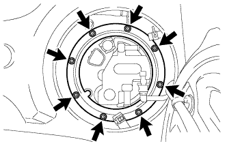
Install the set plate with the 8 bolts.
- Torque:
- 6.0 N*m { 61 kgf*cm, 53 in.*lbf }
Tech Tips
Align the protrusion of the set plate with the groove of the fuel pump.
-
-
CONNECT FUEL TANK MAIN TUBE SUB-ASSEMBLY
-
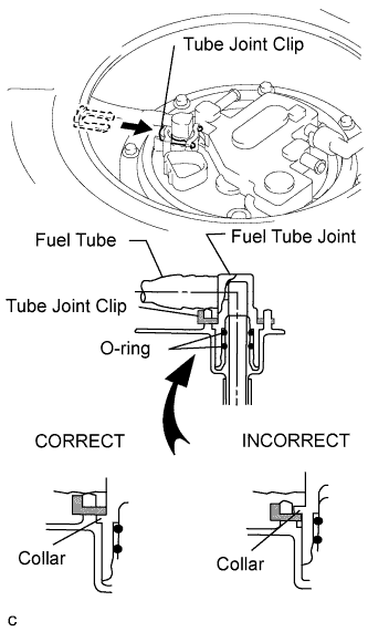
Install the fuel tube with the joint clip.
Note
-
Check that there are no scratches or foreign objects on the connecting parts.
-
Check that the fuel tube joint is inserted securely.
-
Check that the fuel tube joint clip is on the collars of the fuel tube joint.
-
After installing the tube joint clip, check that the fuel tube joint has not been pulled off.
-
Be careful not to damage the clip. If the clip is damaged, replace it.
-
-
-
CONNECT NO. 1 FUEL EVAPORATION TUBE SUB-ASSEMBLY
-
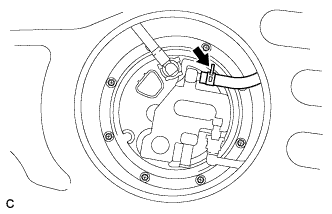
Connect the tube to the fuel tube assembly.
-
-
CONNECT CHARCOAL CANISTER OUTLET TUBE SUB-ASSEMBLY
-
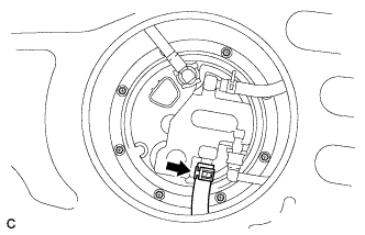
Connect the outlet tube to the fuel tube assembly.
-
-
INSTALL REAR FLOOR SERVICE HOLE COVER
-
Connect the fuel pump connector.
-
Install the service hole cover with new butyl tape and return the floor carpet to its original position.
-
-
INSTALL FUEL TANK CAP
-
INSTALL NO. 1 SEAT TRACK LOWER RAIL PROTECTOR
Tech Tips
Use the same procedure for all seat track lower rail protectors Click here.
-
CONNECT CABLE TO NEGATIVE BATTERY TERMINAL
Note
When disconnecting the cable, some systems need to be initialized after the cable is reconnected Click here.
-
INSPECT FOR FUEL LEAK
-
Check fuel pump operation.
-
Connect the intelligent tester to the DLC3.
-
Turn the engine switch on (IG) and turn the intelligent tester on.
Note
Do not start the engine.
-
Enter the following menus: Powertrain / Engine / Active Test / Control the Fuel Pump / Speed.
-
Check for pressure in the fuel inlet tube from the fuel line. Check that sounds of fuel flowing in the fuel tank can be heard. If no sounds can be heard, check the integration relay, fuel pump, ECM and wiring connectors.
-
-
Inspect for fuel leaks.
-
Check that there is no fuel leakage after performing maintenance anywhere on the fuel system. If there is a fuel leak, repair or replace parts if necessary.
-
-
Turn the engine switch off.
-
Disconnect the intelligent tester from the DLC3.
-