ENGINE ASSEMBLY REMOVAL

-
RECOVER REFRIGERANT FROM REFRIGERATION SYSTEM
-
Start up the engine.
-
Turn the A/C switch on.
-
Operate the cooler compressor at an engine speed of approximately 1000 rpm for 5 to 6 minutes to circulate the refrigerant. This causes most of the compressor oil from the various components of the A/C system to collect in the A/C compressor.
-
Stop the engine.
-
Recover the refrigerant from the A/C system using a refrigerant recovery unit.
-
-
DISCHARGE FUEL SYSTEM PRESSURE
-
ALIGN FRONT WHEELS FACING STRAIGHT AHEAD
-
DISCONNECT CABLE FROM NEGATIVE BATTERY TERMINAL
CAUTION:
When disconnecting the cable, some systems need to be initialized after the cable is reconnected Click here.
-
REMOVE FRONT WHEEL
-
REMOVE NO. 1 ENGINE UNDER COVER
-
REMOVE ENGINE UNDER COVER
-
REMOVE NO. 2 ENGINE UNDER COVER (for Front Side)
-
REMOVE NO. 2 ENGINE UNDER COVER (for Rear Side)
-
REMOVE REAR ENGINE UNDER COVER LH
-
REMOVE REAR ENGINE UNDER COVER RH
-
DRAIN ENGINE OIL
-
Remove the oil filler cap.
-
Remove the oil drain plug and drain the oil into a container.
-
Clean the oil drain plug.
-
Install the oil drain plug with a new gasket.
- Torque:
- 40 N*m { 408 kgf*cm, 30 ft.*lbf }
-
-
DRAIN ENGINE COOLANT
CAUTION:
Do not remove the reserve tank cap, cylinder block drain cock plugs or radiator drain cock plug while the engine and radiator assembly are still hot. Pressurized, hot engine coolant and steam may be released and cause serious burns.
-
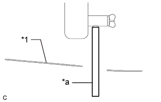
Text in Illustration *1 No. 1 Engine Under Cover *a Hose Connect a hose with an inside diameter of 9 mm (0.354 in.) to the radiator drain cock as shown in the illustration.
-
Loosen the radiator drain cock plug.
-
Remove the reserve tank cap. Then drain the engine coolant.
-
Loosen the cylinder block drain cock plug (for Bank 1).
-
Loosen the cylinder block drain cock plug (for Bank 2, w/ Cylinder Block Drain Cock Plug).
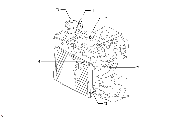
Text in Illustration *1 Radiator Reserve Tank *2 Reserve Tank Cap *3 Radiator Drain Cock Plug *4 Air Drain Cock Plug *5 Cylinder Block Drain Cock Plug (for Bank 1) *6 Cylinder Block Drain Cock Plug (for Bank 2, w/ Cylinder Block Drain Cock Plug) Tech Tips
Collect the engine coolant in a container and dispose of it according to the regulations in your area.
-
Disconnect a hose with an inside diameter of 9 mm (0.354 in.) from the radiator drain cock.
-
-
DRAIN AUTOMATIC TRANSAXLE FLUID
-
Remove the 5 clips and rear engine under cover LH.
-
Using a 6 mm socket hexagon wrench, remove the overflow plug and gasket from the automatic transaxle.
-
Remove the refill plug and gasket from the automatic transaxle.
-
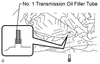
Using a 6 mm socket hexagon wrench, remove the No. 1 transmission oil filler tube from the automatic transaxle.
-
Drain automatic transaxle fluid from the automatic transaxle.
-
Using a 6 mm socket hexagon wrench, install the No. 1 transmission oil filler tube to the automatic transaxle.
- Torque:
- 1.7 N*m { 17 kgf*cm, 15 in.*lbf }
-
Using a 6 mm socket hexagon wrench, install a new gasket and the overflow plug to the automatic transaxle.
- Torque:
- 40 N*m { 408 kgf*cm, 30 ft.*lbf }
-
Install a new gasket and the refill plug to the automatic transaxle.
- Torque:
- 49 N*m { 500 kgf*cm, 36 ft.*lbf }
-
-
REMOVE COWL SIDE TRIM BOARD RH (for RHD)
-

Remove the clip.
-
Disengage the clip, claw and 2 guides, and remove the cowl side trim board RH.
-
-
REMOVE COWL SIDE TRIM BOARD LH (for LHD)
-
Remove the clip(A).
-
Disengage the clip, claw and 2 guides, and remove the cowl side trim board LH.
-
-
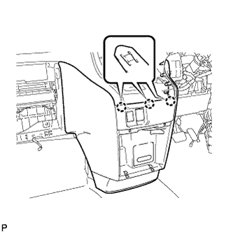
REMOVE NO. 1 INSTRUMENT PANEL UNDER COVER SUB-ASSEMBLY (for RHD)
-

Remove the 2 screws <B>.
-
Disengage the 2 claws and 2 guides.
-
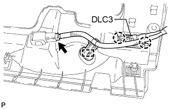
Disengage the 2 claws and disconnect the DLC3.
-
Disengage the clamp.
-
Disconnect each connector and remove the No. 1 instrument panel under cover sub-assembly.
-
-
REMOVE NO. 1 INSTRUMENT PANEL UNDER COVER SUB-ASSEMBLY (for LHD)
-

Remove the 2 screws <B>.
-
Disengage the 2 claws and guide.
-
Disengage the clamp.
-
Disconnect each connector and remove the No. 1 instrument panel under cover sub-assembly.
-
-
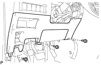
REMOVE LOWER INSTRUMENT PANEL FINISH PANEL (for RHD)
-
Disengage the 3 claws and disconnect the hood lock control cable assembly.
-

Disengage the 3 claws and disconnect the fuel lid lock control cable assembly.
-
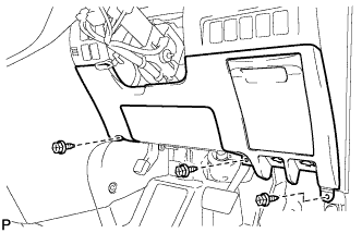
Remove the 3 screws <B>.
-
Disengage the 14 claws and the 3 guides, and remove the lower instrument panel finish panel as shown in the illustration.
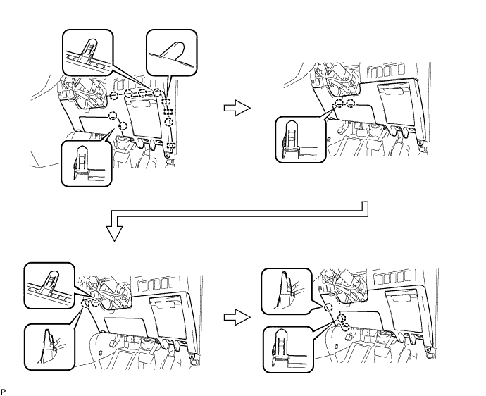
Note
-
Make sure to follow the order shown in the illustration to avoid damage to the lower instrument panel finish panel.
-
While supporting the knee airbag, remove the lower instrument panel finish panel.
-
-
-
REMOVE LOWER INSTRUMENT PANEL FINISH PANEL (for LHD)
-

Disengage the 3 claws and disconnect the hood lock control cable assembly.
-
Disengage the 3 claws and disconnect the fuel lid lock control cable assembly.
-

Disconnect the fuel filler opening lid lock sub-assembly and remove the fuel lid lock open lever sub-assembly.
-
Remove the 3 screws <B>.
-
Disengage the 13 claws, clip and the 3 guides and remove the lower instrument panel finish panel as shown in the illustration.
Note
-
Make sure to follow the order shown in the illustration to avoid damage to the lower instrument panel finish panel.
-
While supporting the knee airbag, remove the lower instrument panel finish panel.
-
-
-
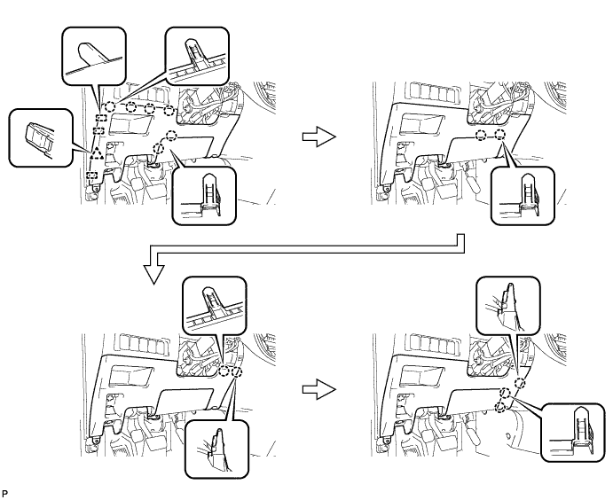
REMOVE CENTER FLOOR CARPET COVER RH (for RHD)
-
Using a clip remover, remove the 2 clips.
-
Disengage the 4 claws and remove the center floor carpet cover RH in the order shown in the illustration.
Tech Tips
Remove the center floor carpet cover RH while pushing on the instrument cluster finish panel.
-
-
REMOVE CENTER FLOOR CARPET COVER RH (for LHD)
-
Using a clip remover, remove the clip.
-
Disengage the 5 claws and remove the center floor carpet cover RH in the order shown in the illustration.
Tech Tips
Remove the center floor carpet cover RH while pushing on the instrument cluster finish panel.
-
-
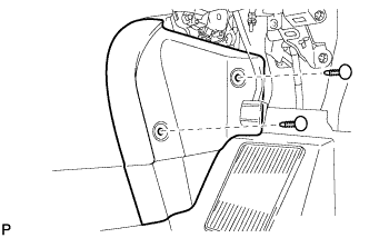
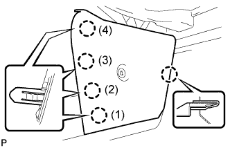
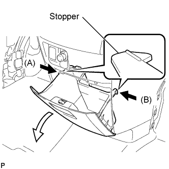
REMOVE GLOVE COMPARTMENT DOOR ASSEMBLY
-
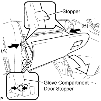
Disengage the claw and release the glove compartment door stopper.
-
Slightly bend stoppers (A) and (B) in the directions indicated by the arrows in the illustration and pull the glove compartment door assembly until the stoppers are released.
-
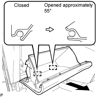
Open the glove compartment door assembly to approximately 55° from its closed position. Pull it horizontally toward the rear of the vehicle to disengage the 2 hinges and remove the glove compartment door assembly.
Note
Pulling the glove compartment door assembly upward to remove it causes the hinges to deform. Be sure to pull out the glove compartment door assembly horizontally.
-
-
REMOVE CENTER FLOOR CARPET COVER LH
-

Using a clip remover, remove the clip.
-
Disengage the 4 claws and remove the center floor carpet cover LH in the order shown in the illustration.
Tech Tips
Remove the center floor carpet cover LH while pushing on the instrument cluster finish panel.
-
-
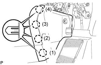
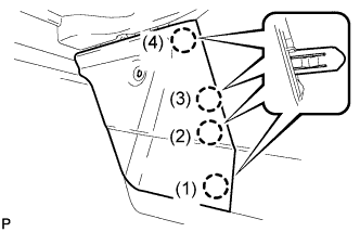
REMOVE INSTRUMENT PANEL BOX ASSEMBLY
-
Slightly bend stoppers (A) and (B) in the directions indicated by the arrows in the illustration and pull the instrument panel box assembly until the stoppers are released.
-
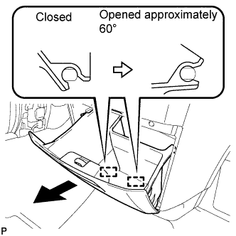
Open the instrument panel box assembly to approximately 60° from its closed position. Pull it horizontally toward the rear of the vehicle to disengage the 2 hinges and remove the instrument panel box assembly.
Note
Pulling the instrument panel box assembly upward to remove it causes the hinges to deform. Be sure to pull out the instrument panel box horizontally.
-
-
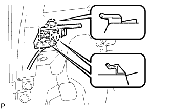
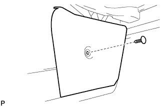
REMOVE INSTRUMENT CLUSTER FINISH PANEL ASSEMBLY
-
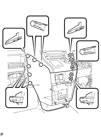
Remove the bolt <C>.
-
Disengage the 12 claws.
Tech Tips
First disengage the 6 claws for the right side and then pull the panel to the rear of the vehicle to disengage the 6 claws for the left side.
-
Disengage the 3 claws.
-
Disconnect each connector and remove the instrument cluster finish panel assembly.
-
-
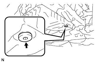
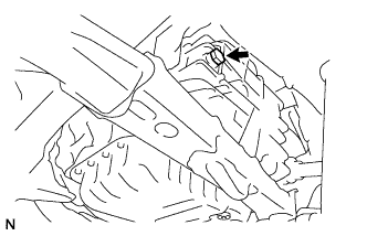
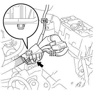
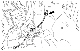
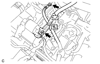
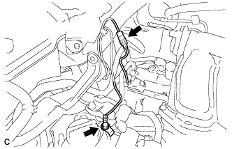
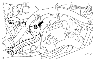
DISCONNECT OXYGEN SENSOR CONNECTOR (for Bank 1 Sensor 2)
-
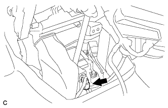
Disconnect the oxygen sensor connector (for Bank 1 Sensor 2).
-
Remove the grommet.
-
-
REMOVE WINDSHIELD WIPER ARM COVER
-
Using a screwdriver, disengage the 2 claws and remove the 2 windshield wiper arm covers.
Tech Tips
Tape the screwdriver tip before use.
-
-
REMOVE FRONT WIPER ARM AND BLADE ASSEMBLY RH
-
Remove the nut and the front wiper arm and blade assembly RH.
-
-
REMOVE FRONT WIPER ARM AND BLADE ASSEMBLY LH
-
Remove the nut and the front wiper arm and blade assembly LH.
-
-
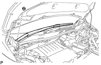
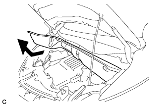
REMOVE COWL TOP VENTILATOR LOUVER SUB-ASSEMBLY
-
Remove the 2 clips.
-
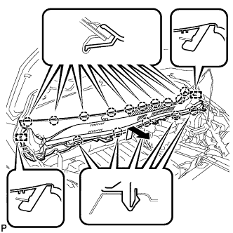
Disengage the 15 claws and 2 guides, and remove the cowl top ventilator louver sub-assembly as shown in the illustration.
-
-
REMOVE WINDSHIELD WIPER MOTOR AND LINK ASSEMBLY
-
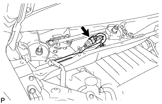
Disconnect the connector.
-
Remove the 3 bolts and the windshield wiper motor and link assembly as shown in the illustration.
-
-
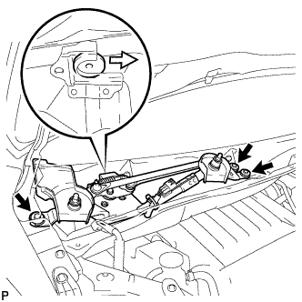
REMOVE BRAKE MASTER CYLINDER RESERVOIR WITH BRACKET
-
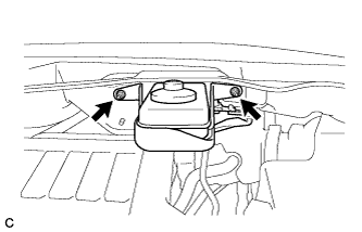
Remove the 2 nuts and separate the brake master cylinder reservoir with bracket from the outer cowl top panel.
-
-
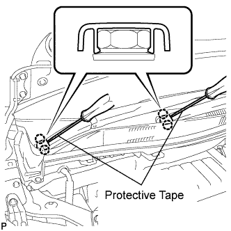
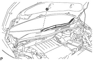
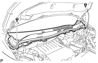
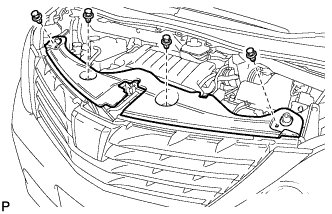
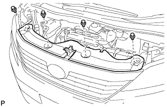
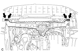
REMOVE OUTER COWL TOP PANEL SUB-ASSEMBLY
-
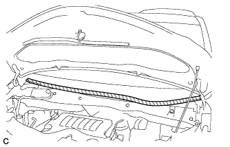
Apply protective tape as shown in the illustration.
Text in Illustration 
Protective Tape -
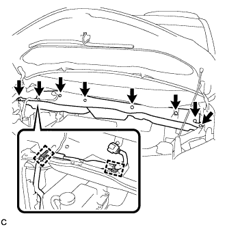
Disconnect the 2 clamps from the outer cowl top panel.
-
Remove the 8 bolts.
-
Remove the outer cowl top panel as shown in the illustration.
-
-
REMOVE RADIATOR COVER SUB-ASSEMBLY (for ALPHARD)
-
Using a clip remover, remove the 4 clips and radiator cover sub-assembly.
-
-
REMOVE RADIATOR COVER SUB-ASSEMBLY (for VELLFIRE)
-
Using a clip remover, remove the 4 clips and radiator cover sub-assembly.
-
-
REMOVE V-BANK COVER SUB-ASSEMBLY
-
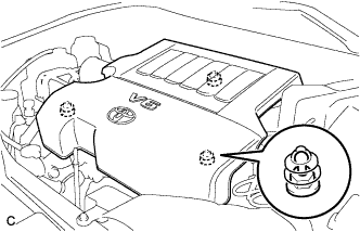
Hold the front of the V-bank cover sub-assembly and raise it to disengage the 2 clips on the front of the cover. Continue to raise the cover to disengage the clip on the rear of the cover and remove the V-bank cover sub-assembly.
Note
Attempting to disengage both front and rear clips at the same time may cause the cover to break.
-
-
REMOVE BATTERY
-
Disconnect the positive (+) cable to the battery positive (+) terminal.
-
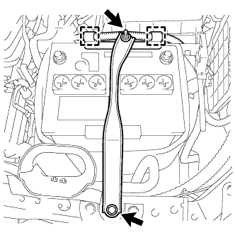
Disconnect the 2 wire clamps.
-
Loosen the nut, and remove the bolt with the battery clamp.
-
Remove the battery, battery insulator and battery tray.
-
-
REMOVE AIR CLEANER CAP SUB-ASSEMBLY
-
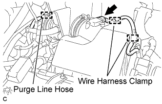
Separate the mass air flow meter connector and 2 wire harness clamps.
-
Separate the purge line hose.
-
Separate the ventilation hose.
-
Loosen the hose clamp and separate the air cleaner hose from the throttle body.
-
Release the 2 clamps and remove the air cleaner cap sub-assembly.
-
-
REMOVE AIR CLEANER CASE
-
Remove the air cleaner filter element.
-
Disconnect the wire clamp.
-
Remove the 3 bolts and air cleaner case.
-
-
REMOVE NO. 2 AIR CLEANER INLET
-
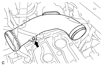
Remove the bolt and No. 2 air cleaner inlet.
-
-
REMOVE BATTERY CARRIER
-
Disconnect the 2 wire clamps.
-
Remove the 4 bolts and battery carrier.
-
-
REMOVE BATTERY CARRIER SUPPORT
-
Remove the 2 bolts and battery carrier support.
-
-
REMOVE RADIATOR RESERVOIR TANK ASSEMBLY
-
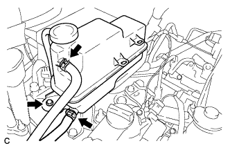
Disconnect the No. 1 and No. 2 water by-pass hoses.
-
Remove the bolt and radiator reservoir tank assembly.
-
-
REMOVE RADIATOR RESERVOIR TANK BRACKET
-
Remove the 2 bolts and radiator reservoir tank bracket.
-
-
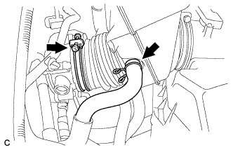
DISCONNECT OIL COOLER HOSE
-
Disconnect the 2 oil cooler hoses.
-
-
DISCONNECT NO. 1 RADIATOR HOSE
-
Disconnect the No. 1 radiator hose.
-
-
DISCONNECT NO. 2 RADIATOR HOSE
-
Disconnect the No. 2 radiator hose.
-
-
DISCONNECT HEATER WATER INLET HOSE
-
Disconnect the heater water inlet hose.
-
-
DISCONNECT HEATER WATER OUTLET HOSE
-
Disconnect the heater water outlet hose.
-
-
DISCONNECT NO. 1 FUEL VAPOR FEED HOSE
-
Disconnect the No. 1 fuel vapor feed hose.
-
-
DISCONNECT UNION TO CONNECTOR TUBE HOSE
-
Disconnect the union to connector tube hose.
-
-
DISCONNECT TRANSMISSION CONTROL CABLE ASSEMBLY
-
Remove the clip and nut, and separate the transmission control cable assembly from the transaxle.
-
-
REMOVE ECM
-
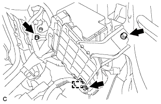
Separate the wire harness clamp.
-
Remove the 3 bolts and separate the ECM with brackets.
-
Disconnect the 2 ECM connectors and remove the ECM with brackets.
Note
After disconnecting the connectors, make sure that dirt, water or other foreign matter does not contact the connecting part of the connectors.
-
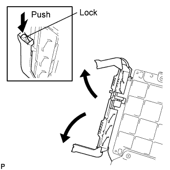
Push in the locks on the 2 levers, raise the levers, and disconnect the 2 ECM connectors.
-
-
Remove the 4 screws and 2 ECM brackets.
-
-
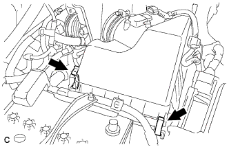
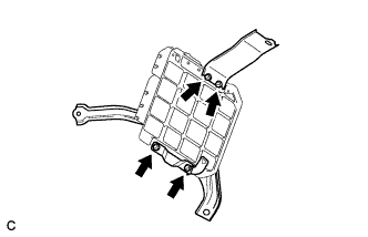
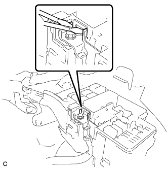
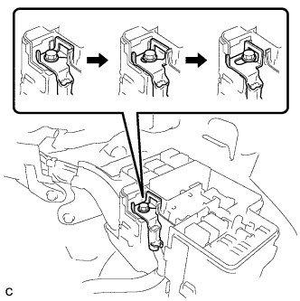
DISCONNECT ENGINE WIRE
-
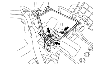
Remove the engine room relay block cover.
-
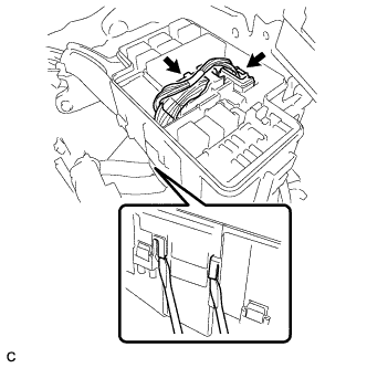
Disconnect the 2 connectors.
-
Using a screwdriver, unlock the 2 claws and separate the engine wire from the engine room relay block.
-
Using a screwdriver, unlock the 2 claws and loosen the bolt.
-
Slide the battery positive (+) cable as shown in the illustration.
-
Remove the bolt and 3 clamps, and separate the wire harness protector from the bracket.
-
Remove the bolt and clamp, and separate the ground cable from the body.
-
Disconnect the clamp, remove the nut, and disconnect the battery positive (+) cable.
-
Disconnect the clamp, remove the bolt, and disconnect the ground cable.
-
Disconnect the connector, remove the bolt, and disconnect the ground cable.
-
-
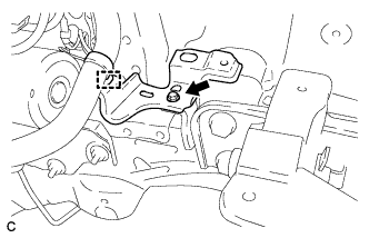
REMOVE NO. 2 ENGINE MOUNTING STAY RH
-
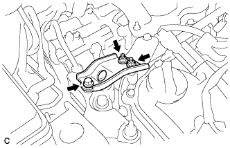
Remove the bolt, 2 nuts and No. 2 engine mounting stay RH.
-
-
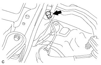
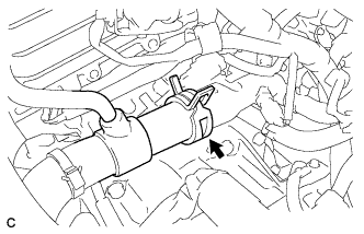
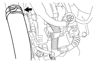
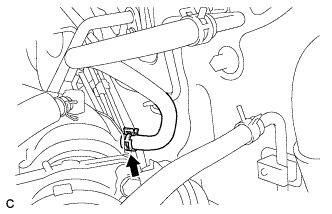
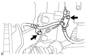
DISCONNECT NO. 1 COOLER REFRIGERANT DISCHARGE HOSE
-
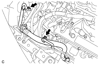
Remove the nut and disconnect the No. 1 cooler refrigerant discharge hose.
Note
Seal the openings of the disconnected parts using vinyl tape to prevent entry of moisture and foreign matter.
-
-
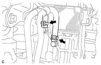
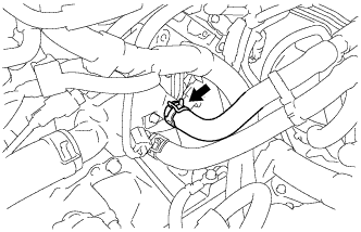
DISCONNECT NO. 1 COOLER REFRIGERANT SUCTION HOSE
-
Disconnect the clamp.
-
Remove the nut and disconnect the No. 1 cooler refrigerant suction hose.
Note
Seal the openings of the disconnected parts using vinyl tape to prevent entry of moisture and foreign matter.
-
-
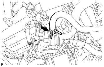
DISCONNECT FUEL MAIN TUBE
-
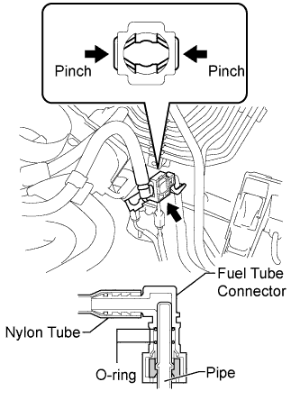
Disengage the claw and open the No. 1 EFI fuel pipe clamp cover.
Tech Tips
Do not remove the No. 1 EFI fuel pipe clamp from the pipe.
-
Pinch the fuel tube connector and then pull out the fuel main tube.
Note
-
Check for any dirt and foreign matter contamination in the pipe and around the connector. Clean if necessary. Foreign matter may damage the O-rings or cause leaks in the seal between the pipe and connector.
-
Do not use any tools to separate the pipe and connector.
-
Do not forcefully bend or twist the nylon tube.
-
Check for any dirt and foreign matter on the pipe seal surface. Clean if necessary.
-
Put the pipe and connector ends in plastic bags to prevent damage and dirt contamination.
-
If the pipe and connector are stuck together, pinch the tube between your fingers and turn it carefully to free it. Then disconnect the hose.
-
-
-
REMOVE CENTER EXHAUST PIPE ASSEMBLY (for Front Side)
-
Remove the 4 bolts, 2 nuts, 2 compression springs and center exhaust pipe assembly (for Front Side).
-
Remove the 3 gaskets from the center exhaust pipe assembly (for Front Side).
-
-
REMOVE FRONT EXHAUST PIPE ASSEMBLY
-
Disconnect the No. 2 oxygen sensor connector (for Bank 2).
-
Remove the 2 bolts and No. 1 exhaust pipe support bracket.
-
Remove the 2 nuts and front exhaust pipe assembly.
-
Remove the gasket from the front exhaust pipe assembly.
-
-
SECURE STEERING WHEEL
-
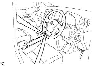
Secure the steering wheel with the seat belt in order to prevent rotation.
Tech Tips
This operation is useful to prevent damage to the spiral cable.
-
-
REMOVE COLUMN HOLE COVER SILENCER SHEET
-
Remove the 2 clips and column hole cover silencer sheet.
-
-
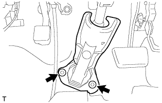
SEPARATE NO. 2 STEERING INTERMEDIATE SHAFT ASSEMBLY
-
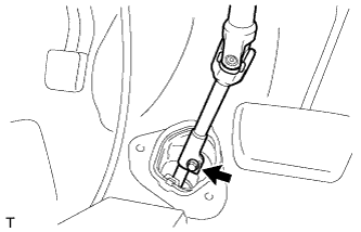
Remove the bolt from the No. 2 steering intermediate shaft assembly.
-
Slide the No. 2 steering intermediate shaft assembly toward the steering column assembly.
Note
Do not separate the No. 2 steering intermediate shaft assembly from the steering intermediate shaft assembly.
-
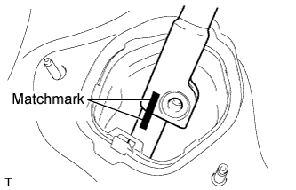
Put matchmarks on the No. 2 steering intermediate shaft assembly and the steering intermediate shaft assembly.
-
Separate the No. 2 steering intermediate shaft assembly from the steering intermediate shaft assembly.
-
-
DISCONNECT NO. 1 STEERING COLUMN HOLE COVER SUB-ASSEMBLY
-
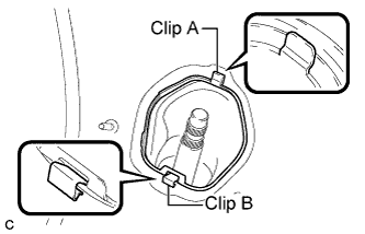
Push clip B towards center of the hole to release it, then push on clip A and remove the No. 1 steering column hole cover sub-assembly from the body.
Note
Do not damage clip A and B.
-
-
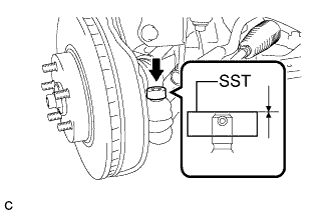
REMOVE FRONT AXLE SHAFT NUT LH
-
Using SST and a hammer, release the staked part of the front axle shaft nut.
- SST
- 09930-00010
Note
-
Insert SST into the groove with the flat surface facing up.
-
Do not damage the tip of SST using a grinder.
-
Completely unstake the staked part before removing the front axle shaft nut.
-
Do not damage the threads of the drive shaft.
-
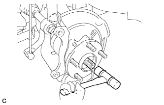
Using a socket wrench (30 mm), remove the front axle shaft nut.
-
-
REMOVE FRONT AXLE SHAFT NUT RH
Tech Tips
Perform the same procedure as for the LH side.
-
SEPARATE FRONT SPEED SENSOR LH
-
Remove the 2 bolts and separate the front flexible hose and the front speed sensor from the front shock absorber and steering knuckle.
-
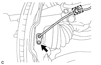
Remove the bolt and clamp to separate the front speed sensor from the steering knuckle.
-
-
SEPARATE FRONT SPEED SENSOR RH
Tech Tips
Perform the same procedure as for the LH side.
-
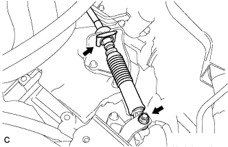
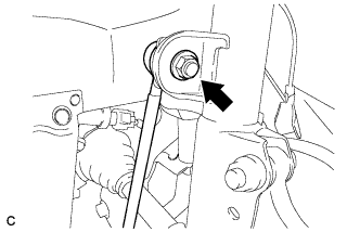
SEPARATE TIE ROD END SUB-ASSEMBLY LH
-
Remove the cotter pin and nut.
-
Install SST to the tie rod end.
- SST
- 09960-20010 ( 09961-02060 )
Note
Make sure that the upper end of the tie rod end and SST are aligned.
-
Using SST, separate the tie rod end from the steering knuckle.
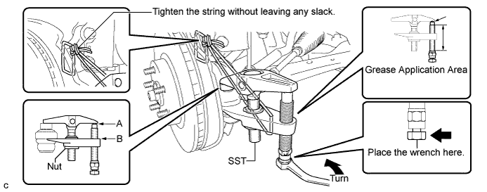
- SST
- 09960-20010 ( 09961-02010 )
CAUTION:
Apply grease to the bolt threads and the tip of SST.
Note
-
Be sure to tighten the string firmly to secure SST to the steering knuckle to prevent SST from falling off.
-
Install SST with the center nut so that A and B shown in the illustration are parallel. Otherwise, the dust cover may be damaged.
-
Be sure to place the wrench on the part indicated in the illustration.
-
Do not damage the front disc brake dust cover.
-
Do not damage the ball joint dust cover.
-
Do not damage the steering knuckle.
-
-
SEPARATE TIE ROD END SUB-ASSEMBLY RH
Tech Tips
Perform the same procedure as for the LH side.
-
SEPARATE FRONT STABILIZER LINK ASSEMBLY LH
-
Remove the nut and separate the front stabilizer link assembly LH from the front shock absorber.
Note
If the ball joint turns together with the nut, use a hexagon wrench (6 mm) to hold the stud bolt.
-
-
SEPARATE FRONT STABILIZER LINK ASSEMBLY RH
Tech Tips
Perform the same procedure as for the LH side.
-
SEPARATE FRONT DISC BRAKE CALIPER ASSEMBLY LH
-
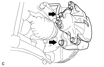
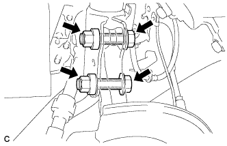
Remove the 2 bolts and separate the front disc brake caliper assembly from the steering knuckle.
Note
Use wire or an equivalent tool to keep the brake caliper from hanging down by the flexible hose.
-
-
SEPARATE FRONT DISC BRAKE CALIPER ASSEMBLY RH
Tech Tips
Perform the same procedure as for the LH side.
-
REMOVE FRONT DISC (for LH Side)
-
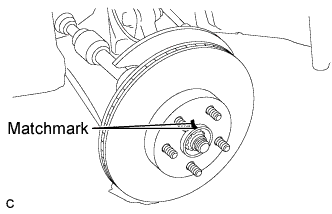
Put matchmarks on the front disc and front axle hub.
Tech Tips
The above step is not necessary when the front disc will be replaced.
-
Remove the front disc.
-
-
REMOVE FRONT DISC (for RH Side)
Tech Tips
Perform the same procedure as for the LH side.
-
SEPARATE FRONT LOWER NO. 1 SUSPENSION ARM SUB-ASSEMBLY LH
-
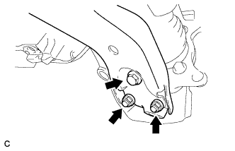
Remove the bolt and 2 nuts, and then pull down the front lower suspension arm sub-assembly to separate the front lower suspension arm sub-assembly from the front lower ball joint.
-
-
SEPARATE FRONT LOWER NO. 1 SUSPENSION ARM SUB-ASSEMBLY RH
Tech Tips
Perform the same procedure as for the LH side.
-
REMOVE FRONT AXLE ASSEMBLY LH
-
Using a plastic hammer, separate the front drive shaft assembly from the front axle assembly.
Tech Tips
If it is difficult to disengage the fitting, tap the end of the drive shaft with a brass bar and a hammer.
-
Remove the 2 bolts and 2 nuts.
-
Remove the front axle assembly from the front drive shaft assembly.
Note
-
Do not deform the dust cover.
-
Do not damage the outboard joint boot.
-
Do not damage the speed sensor rotor.
-
Do not drop the front axle assembly.
-
Use the wire or an equivalent tool to hang the front drive shaft assembly.
-
-
-
REMOVE FRONT AXLE ASSEMBLY RH
Tech Tips
Perform the same procedure as for the LH side.
-
REMOVE FRONT DRIVE SHAFT ASSEMBLY LH
-
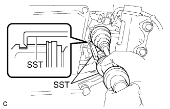
Using SST, remove the front drive shaft assembly LH.
- SST
- 09520-00031
- 09520-01010
- 09521-00020
Note
-
Do not damage the transaxle case oil seal.
-
Do not damage the inboard joint boot.
-
Do not drop the front drive shaft assembly LH.
-
-
REMOVE FRONT DRIVE SHAFT HOLE SNAP RING LH
-
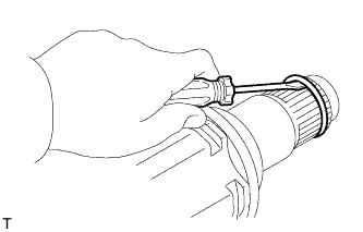
Using a screwdriver, remove the front drive shaft hole snap ring LH.
-
-
REMOVE FRONT DRIVE SHAFT ASSEMBLY RH
-
Remove the 2 bolts and front drive shaft assembly RH from the vehicle.
Note
-
Do not damage the front transaxle case oil seal.
-
Do not damage the inboard joint boot.
-
Do not drop the front drive shaft assembly RH.
-
-
-
REMOVE NO. 1 EXHAUST PIPE SUPPORT BRACKET
-
Remove the 2 bolts and No. 1 exhaust pipe support bracket.
-
-
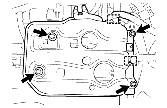
REMOVE FLYWHEEL HOUSING UNDER COVER
-
Remove the 2 bolts and flywheel housing under cover.
-
-
REMOVE DRIVE PLATE AND TORQUE CONVERTER CLUTCH SETTING BOLT
-
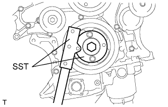
Using SST, hold the crankshaft pulley.
- SST
- 09213-70011 ( 09213-70020 )
- 09330-00021
-
Remove the 6 drive plate and torque converter clutch setting bolts.
Tech Tips
There will be one black colored bolt.
-
-
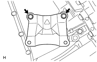
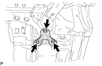
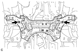
REMOVE FRONT SUSPENSION MEMBER REINFORCEMENT LH
-
Remove the 4 bolts and the front suspension member reinforcement LH.
-
-
REMOVE FRONT SUSPENSION MEMBER REINFORCEMENT RH
Tech Tips
Perform the same procedure as for the LH side.
-
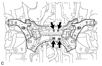
REMOVE FRONT SUSPENSION MEMBER BRACE SUB-ASSEMBLY
-
Remove the 3 bolts and front suspension member brace sub-assembly (LH side).
-
Perform the same procedure for the front suspension member brace sub-assembly (RH side).
-
-
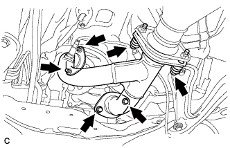
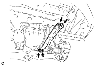
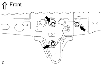
REMOVE FRONT SUSPENSION CROSSMEMBER SUB-ASSEMBLY
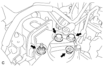
-
Remove the 2 bolts and 2 nuts, and separate the front suspension crossmember sub-assembly from the rear engine mounting insulator.
-
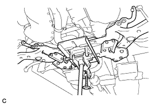
Using a transmission jack or equivalent, support the front suspension crossmember sub-assembly.
-
Remove the 2 bolts.
-
Slowly lower the jack, and remove the front suspension crossmember sub-assembly from the vehicle.
-
-
REMOVE ENGINE ASSEMBLY WITH TRANSAXLE
-
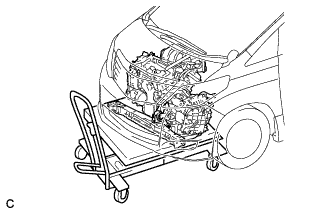
Set the engine lifter.
Note
-
Install a height adjustment attachment and plate lift attachment onto the engine assembly with transaxle.
-
Do not position a height adjustment attachment or plate lift attachment onto the front crossmember sub-assembly.
-
Securely support the engine assembly to prevent it from turning upside down until it is secured to an engine stand.
-
Do not perform any procedure while the engine assembly is suspended because doing so may cause the engine assembly to drop, resulting in injury. However, the engine assembly needs to be suspended when it is installed to or removed from an engine stand.
-
-
Remove the 4 bolts and front crossmember sub-assembly.
-
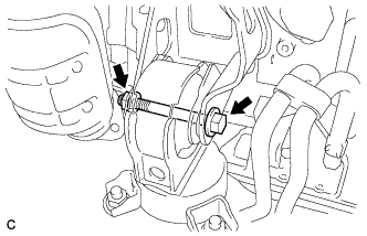
Remove the 2 bolts and 2 nuts, and separate the engine mounting insulator sub-assembly RH.
-
Remove the through bolt and nut, and separate the engine mounting insulator LH.
-
Carefully remove the engine with transaxle from the vehicle.
Note
-
Make sure that the engine is clear of all wiring and hoses.
-
While lowering the engine from the vehicle, do not allow it to contact the vehicle.
-
-
Install the No. 1 and No. 2 engine hangers with the 4 bolts.
- Torque:
- 33 N*m { 337 kgf*cm, 24 ft.*lbf }
Part No. Item Part No. No. 1 engine hanger 12281-31120 No. 2 engine hanger 12282-31100 Bolt 91671-10825 -
Attach the sling device to the engine hangers and chain block.
-
-
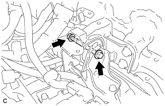
DISCONNECT FRONT CROSSMEMBER SUB-ASSEMBLY
-
Remove the 3 bolts and disconnect the front engine mounting insulator.
-
-
REMOVE FRONT ENGINE MOUNTING INSULATOR
-
Remove the through bolt, nut and front engine mounting insulator.
-
-
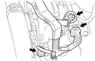
REMOVE REAR ENGINE MOUNTING INSULATOR
-
Remove the through bolt and rear engine mounting insulator.
-
-
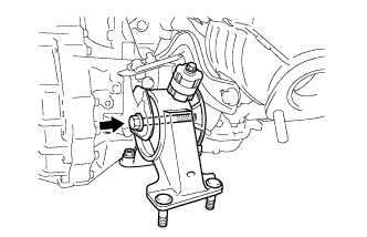
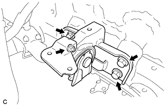
REMOVE ENGINE MOUNTING INSULATOR SUB-ASSEMBLY RH
-
Disconnect the 4 clamps and remove the nut and bracket.
-
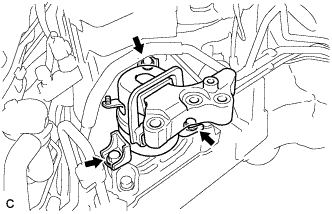
Remove the 3 bolts and engine mounting insulator sub-assembly RH.
-
-
REMOVE ENGINE MOUNTING INSULATOR LH
-
Disconnect the clamp and remove the bolt and bracket.
-
Remove the 4 bolts and engine mounting insulator LH.
-
-
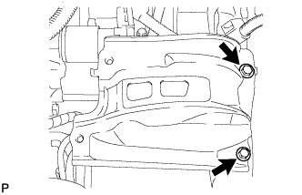
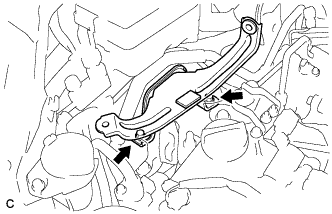
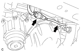
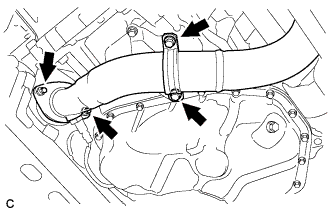
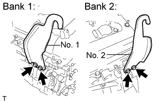
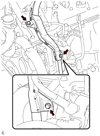
REMOVE MANIFOLD STAY
-
Remove the 2 bolts, nut and manifold stay.
-
-
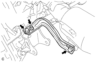
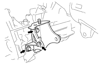
REMOVE FRONT ENGINE MOUNTING BRACKET
-
Remove the 3 bolts and front engine mounting bracket.
-
-
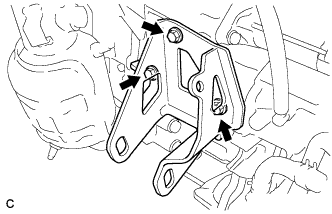
REMOVE REAR ENGINE MOUNTING BRACKET
-
Remove the 3 bolts and rear engine mounting bracket.
-
-
REMOVE V-RIBBED BELT
-
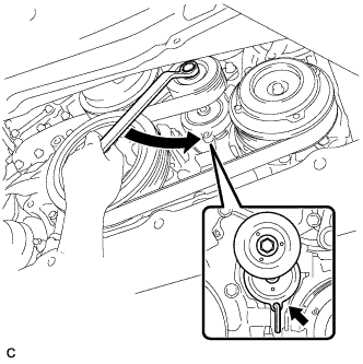
Release the V-ribbed belt tension by turning the V-ribbed belt tensioner counterclockwise, and remove the V-ribbed belt from the V-ribbed belt tensioner.
-
While turning the V-ribbed belt tensioner counterclockwise, align with its holes, and then insert a 5 mm bi-hexagon wrench into the holes to fix the V-ribbed belt tensioner.
-
-
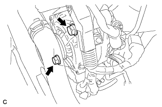
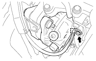
REMOVE GENERATOR ASSEMBLY
-
Remove the 2 bolts.
-
Remove the terminal cap.
-
Remove the nut and disconnect the wire harness from terminal B.
-
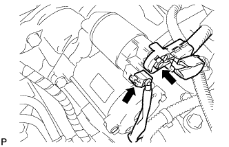
Disconnect the generator connector from the generator assembly.
-
Disconnect the connector from the compressor and magnetic clutch.
-
Disconnect the wire harness clamp.
-
Remove the 2 bolts.
-
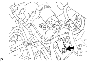
Remove the bolt from the cylinder block.
-
Disconnect the wire harness clamp and remove the generator assembly.
-
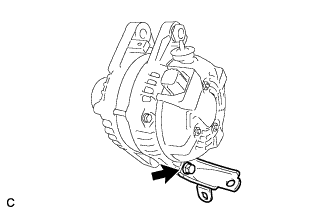
Remove the bolt and bracket.
-
-
REMOVE COMPRESSOR ASSEMBLY WITH PULLEY
-
w/ No. 2 Air Conditioning Tube:
-
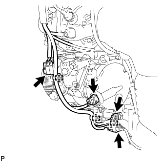
Disengage each clamp.
-
Disconnect each connector.
-
-
w/o No. 2 Air Conditioning Tube:
-
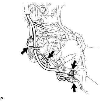
Disengage each clamp.
-
Disconnect each connector.
-
-
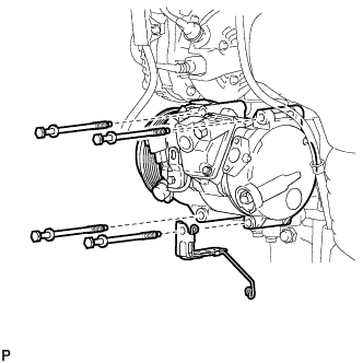
Remove the 4 bolts, bracket, and the compressor and magnetic clutch.
-
-
REMOVE STARTER ASSEMBLY
-
Disconnect the starter connector.
-
Open the terminal cap, remove the nut and disconnect the starter wire.
-
Remove the bolt and wire harness clamp bracket.
-
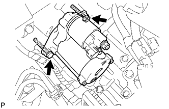
Remove the 2 bolts and starter.
-
-
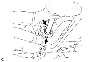
REMOVE DRIVE SHAFT BEARING BRACKET
-
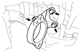
Remove the 3 bolts and drive shaft bearing bracket.
-
-
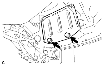
REMOVE ENGINE WIRE
-
REMOVE TRANSMISSION BREATHER SKIRT
-
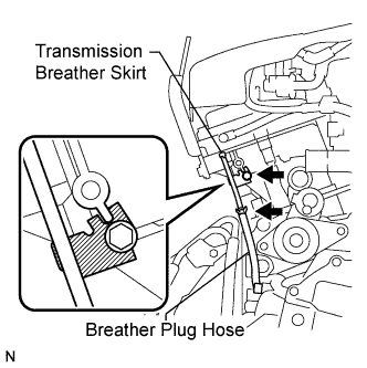
Slide the clip and disconnect the breather plug hose from the transmission breather skirt.
-
Remove the bolt and transmission breather skirt from the engine cylinder head.
-
-
REMOVE AUTOMATIC TRANSAXLE ASSEMBLY
-
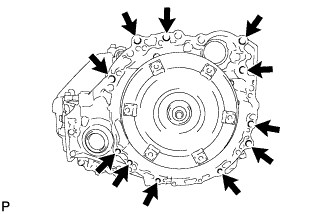
Remove the 11 bolts and transaxle.
Note
To prevent damage to the knock pins, do not pry between the transaxle and engine.
-
-
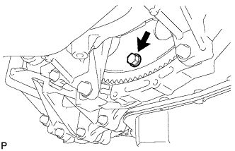
REMOVE DRIVE PLATE AND RING GEAR SUB-ASSEMBLY
-
Using SST, hold the crankshaft pulley.
- SST
- 09213-70011 ( 09213-70020 )
- 09330-00021
-
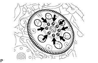
Remove the 8 bolts, front drive plate spacer, drive plate and ring gear sub-assembly and rear drive plate spacer.
-