ENGINE ASSEMBLY INSTALLATION

-
REMOVE ENGINE STAND
-
Remove the engine from the engine stand.
-
-
INSTALL DRIVE PLATE AND RING GEAR SUB-ASSEMBLY
-

Using SST, hold the crankshaft.
- SST
- 09213-54015 ( 91651-60855 )
- 09330-00021
-
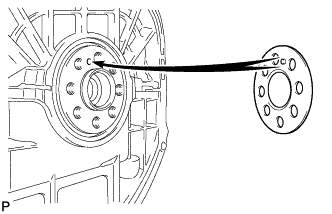
Install the front spacer.
Tech Tips
Align the pin of the front spacer with the pin hole of the crankshaft.
-
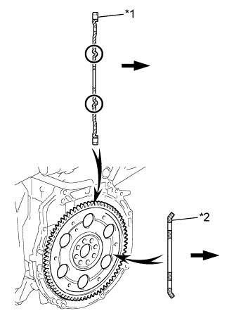
Text in Illustration *1 Drive Plate And Ring Gear Sub-Assembly *2 Rear Spacer 
Transaxle Install the drive plate and ring gear sub-assembly and rear spacer onto the crankshaft.
-
Clean the 8 bolts and 8 bolt holes.
-
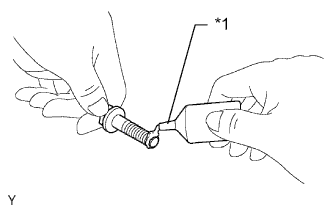
Text in Illustration *1 Adhesive Apply adhesive to 2 or 3 threads of the 8 bolts.
Adhesive Toyota Genuine Adhesive 1324, Three Bond 1324 or equivalent -
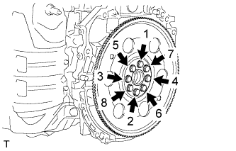
In several steps, uniformly install and tighten the 8 bolts in the sequence shown in the illustration.
- Torque:
- 98 N*m { 999 kgf*cm, 72 ft.*lbf }
Note
Do not start the engine for at least an hour after installing the drive plate.
-
-
INSTALL AUTOMATIC TRANSAXLE ASSEMBLY (for Automatic Transaxle)
-
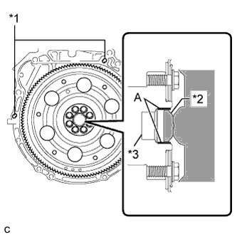
Text in Illustration *1 Knock Pin *2 Torque Converter Centerpiece *3 Crankshaft Confirm that 2 knock pins are on the transaxle contact surface of the engine cylinder block before transaxle installation.
-
Apply clutch spline grease to the round of the crankshaft surface (A) with the torque converter centerpiece.
Clutch spline grease Toyota Genuine Clutch Spline Grease or equivalent Maximum spread About 1 g (0.0353 oz) -
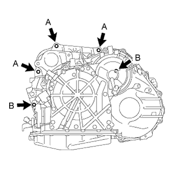
Install the automatic transaxle to the engine with the 5 upper side mounting bolts.
- Torque:
- 64 N*m { 653 kgf*cm, 47 ft.*lbf, for bolt A }
- 46 N*m { 469 kgf*cm, 34 ft.*lbf, for bolt B }
-
Install the 4 lower side mounting bolts.
- Torque:
- 44 N*m { 448 kgf*cm, 32 ft.*lbf }
-
-
INSTALL CONTINUOUSLY VARIABLE TRANSAXLE ASSEMBLY (for CVT)
-
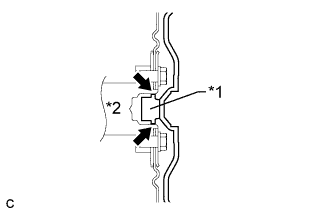
Text in Illustration *1 Torque Converter Assembly Centerpiece *2 Crankshaft Apply clutch spline grease to the circumference of the crankshaft contact surface with the torque converter assembly centerpiece.
Clutch spline grease Toyota Genuine Clutch Spline Grease or equivalent Maximum spread About 1 g (0.0353 oz.) -
Confirm that 2 knock pins are on the transaxle contact surface of the engine cylinder before transaxle installation.
-
Apply adhesive to the threads of a new bolt labeled D.
Adhesive Toyota Genuine Adhesive 1324, Three Bond 1324 or equivalent -
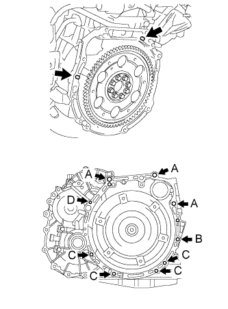
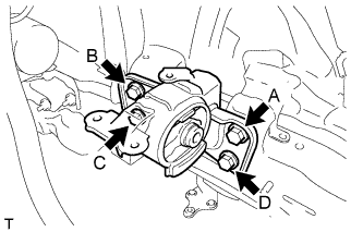
Maintain the engine and continuously variable transaxle assembly in a horizontal position, align the knock pins with each hole on the continuously variable transaxle assembly and install the continuously variable transaxle assembly with the 9 bolts shown in the illustration.
- Torque:
- for bolt A
- 64 N*m { 653 kgf*cm, 47 ft.*lbf }
- for bolt B
- 46 N*m { 469 kgf*cm, 34 ft.*lbf }
- for bolt C
- 44 N*m { 449 kgf*cm, 32 ft.*lbf }
- for bolt D
- 28 N*m { 286 kgf*cm, 21 ft.*lbf }
Bolt length for bolt A 55 mm (2.17 in.) for bolt B 65 mm (2.56 in.) for bolt C 32 mm (1.26 in.) for bolt D 38 mm (1.50 in.) Tech Tips
Bolt A and B: Install from transaxle side
Bolt C and D: Install from engine side
Note
-
Do not use excessive force when installing the continuously variable transaxle assembly.
-
Make sure that the torque converter assembly rotates.
-
Do not reuse bolt D.
-
Before applying adhesive 1324 to bolt D, remove any sealant from its installation hole in the continuously variable transaxle assembly.
-
After installing bolt D, leave the continuously variable transaxle assembly at least 1 hour.
-
-
INSTALL FRONT ENGINE MOUNTING BRACKET
-
Install the front engine mounting bracket to the continuously variable transaxle assembly with the 3 bolts.
- Torque:
- 64 N*m { 653 kgf*cm, 47 ft.*lbf }
-
-
INSTALL REAR ENGINE MOUNTING BRACKET
-
Install the rear engine mounting bracket to the continuously variable transaxle with the 3 bolts.
- Torque:
- 45 N*m { 459 kgf*cm, 33 ft.*lbf }
-
-
CONNECT NO. 5 WATER BY-PASS HOSE (for CVT)
-
Connect the No. 5 water by-pass hose.
-
-
INSTALL STARTER ASSEMBLY (for 1.6 kW Type)
-
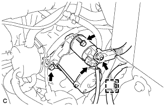
Install the starter with the 2 bolts.
- Torque:
- 37 N*m { 377 kgf*cm, 27 ft.*lbf }
-
Connect the starter connector.
-
Connect the clamp.
-
Install the terminal nut, and cover the nut with the cap.
- Torque:
- 9.8 N*m { 100 kgf*cm, 87 in.*lbf }
-
-
INSTALL STARTER ASSEMBLY (for 1.7 kW Type)
-

Install the starter with the 2 bolts.
- Torque:
- 37 N*m { 377 kgf*cm, 27 ft.*lbf }
-
Connect the starter connector.
-
Connect the clamp.
-
Install the terminal nut, and cover the nut with the cap.
- Torque:
- 9.8 N*m { 100 kgf*cm, 87 in.*lbf }
-
-
TEMPORARILY TIGHTEN FRONT ENGINE MOUNTING INSULATOR
-
Temporarily install the front engine mounting insulator with the nut and through bolt.
-
-
TEMPORARILY TIGHTEN REAR ENGINE MOUNTING INSULATOR
-
Temporarily install the rear engine mounting insulator to the engine mounting bracket with the through bolt.
-
-
INSTALL FRONT CROSSMEMBER SUB-ASSEMBLY
-
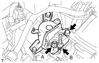
Temporarily install the front crossmember to the front engine mounting insulator with the bolt A, then tighten the bolt B.
- Torque:
- 95 N*m { 969 kgf*cm, 70 ft.*lbf }
-
Tighten the bolt A.
- Torque:
- 95 N*m { 969 kgf*cm, 70 ft.*lbf }
-
-
INSTALL ENGINE MOUNTING INSULATOR SUB-ASSEMBLY RH
Tech Tips
Perform this procedure only when replacement of the engine mounting insulator is necessary.
-
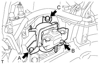
Temporarily install the engine mounting insulator RH with the bolt A, then tighten the bolts in the order of B and C.
- Torque:
- 95 N*m { 969 kgf*cm, 70 ft.*lbf }
-
Tighten the bolt A.
- Torque:
- 95 N*m { 969 kgf*cm, 70 ft.*lbf }
-
Install the bracket with the nut.
- Torque:
- 9.8 N*m { 100 kgf*cm, 87 in.*lbf }
-
Connect the 4 clamps.
-
-
INSTALL ENGINE MOUNTING INSULATOR LH
Tech Tips
Perform this procedure only when replacement of the engine mounting insulator is necessary.
-
Temporarily install the engine mounting insulator LH with the bolt A, then tighten the bolts in the order of B, C and then D.
- Torque:
- 95 N*m { 969 kgf*cm, 70 ft.*lbf }
-
Tighten the bolt A.
- Torque:
- 95 N*m { 969 kgf*cm, 70 ft.*lbf }
-
Install the bracket with the bolt.
-
Connect the wire clamp.
-
-
INSTALL ENGINE ASSEMBLY WITH TRANSAXLE
-
Set the engine assembly with transaxle on the engine lifter.
Note
-
Install a height adjustment attachment and plate lift attachment onto the engine assembly with transaxle.
-
Do not position a height adjustment attachment or plate lift attachment onto the front crossmember sub-assembly.
Tech Tips
Place the engine on wooden blocks or equivalent so that the engine is level.
-
-
Remove the 2 bolts and 2 engine hangers.
-
Operate the engine lifter and lift the engine assembly with transaxle to the position where the engine mounting insulators RH and LH can be installed.
Note
Do not raise the engine more than necessary. If the engine is raised excessively, the vehicle may also be lifted up.
Tech Tips
-
Make sure that the engine is clear of all wiring and hoses.
-
While raising the engine into the vehicle, do not allow it to contact the vehicle.
-
-
Install the engine mounting insulator RH with the bolt and 2 nuts.
- Torque:
- Bolt
- 95 N*m { 969 kgf*cm, 70 ft.*lbf }
- Nut A
- 95 N*m { 969 kgf*cm, 70 ft.*lbf }
- Nut B
- 52 N*m { 530 kgf*cm, 38 ft.*lbf }
-
Install the engine mounting insulator LH with the through bolt and nut. Tighten the nut.
- Torque:
- 56 N*m { 571 kgf*cm, 41 ft.*lbf }
-
Install the front crossmember sub-assembly with the 4 bolts.
- Torque:
- 96 N*m { 979 kgf*cm, 71 ft.*lbf }
-
-
INSTALL FRONT SUSPENSION CROSSMEMBER SUB-ASSEMBLY
-
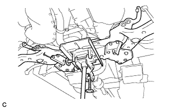
Raise the front suspension crossmember sub-assembly with a transmission jack.
-
Temporarily install the front suspension crossmember sub-assembly with the 2 bolts.
-
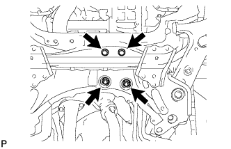
Temporarily install the front suspension crossmember sub-assembly to the rear engine mounting insulator with the 2 bolts and 2 nuts.
-
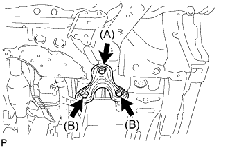
Temporarily install the front suspension member brace (LH side and RH side) with the 2 bolts (A) and 4 bolts (B).
-
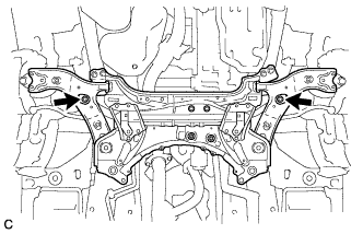
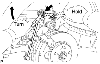
Alternately insert SST into the positioning holes on the front suspension crossmember RH and LH while tightening the bolts on the LH and RH sides to the specified torque using several steps.
- SST
- 09670-00010
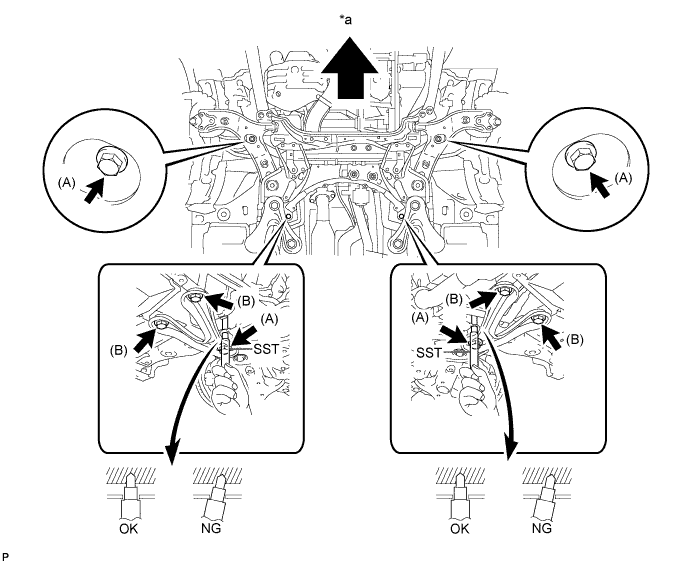
Text in Illustration *a Front of the Vehicle - - - Torque:
- Bolt (A)
- 137 N*m { 1397 kgf*cm, 101 ft.*lbf }
- Bolt (B)
- 93 N*m { 948 kgf*cm, 69 ft.*lbf }
-
Fully tighten the 2 bolts and 2 nuts.
- Torque:
- 95 N*m { 969 kgf*cm, 70 ft.*lbf }
-
-
INSTALL FRONT SUSPENSION MEMBER REINFORCEMENT RH
-
Install the front suspension member reinforcement RH with the 4 bolts.
- Torque:
- 96 N*m { 978 kgf*cm, 71 ft.*lbf }
-
-
INSTALL FRONT SUSPENSION MEMBER REINFORCEMENT LH
Tech Tips
Perform the same procedure as for the RH side.
-
FULLY TIGHTEN FRONT ENGINE MOUNTING INSULATOR
-
Fully tighten the front engine mounting insulator with the nut and through bolt. Tighten the through bolt.
- Torque:
- 145 N*m { 1479 kgf*cm, 107 ft.*lbf }
-
-
FULLY TIGHTEN REAR ENGINE MOUNTING INSULATOR
-
Fully tighten the rear engine mounting insulator to the engine mounting bracket with the through bolt.
- Torque:
- 95 N*m { 969 kgf*cm, 70 ft.*lbf }
-
-
INSTALL DRIVE PLATE AND TORQUE CONVERTER CLUTCH SETTING BOLT
-
Using SST, hold the crankshaft pulley.
- SST
- 09213-54015 ( 91651-60855 )
- 09330-00021
-
Text in Illustration *1 Adhesive Apply a few drops of adhesive to 2 or 3 threads of the 6 drive plate and torque converter clutch setting bolt tips.
Adhesive Toyota Genuine Adhesive 1324, Three Bond 1324 or equivalent. -
Tighten the 6 drive plate and torque converter clutch setting bolts.
- Torque:
- 41 N*m { 418 kgf*cm, 30 ft.*lbf }
Note
Install the black colored bolt first, and then the 5 silver colored bolts.
-
-
INSTALL FLYWHEEL HOUSING UNDER COVER
-
Install the flywheel housing under cover.
-
-
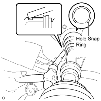
INSTALL FRONT DRIVE SHAFT HOLE SNAP RING LH
-
Install a new front drive shaft hole snap ring LH to the front drive inboard joint assembly LH.
Tech Tips
Face the end gap of the front drive inboard joint hole snap ring downward.
-
-
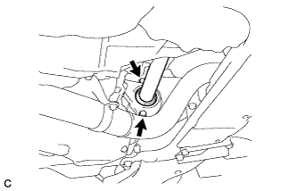
INSTALL FRONT DRIVE SHAFT ASSEMBLY LH
-
Coat the splines of the inboard joint shaft with MP grease.
-
Align the inboard joint splines, and using a brass bar and a hammer, install the front drive shaft assembly LH.
Note
-
Face the end gap of the front drive shaft hole snap ring LH downward.
-
Do not damage the transaxle case oil seal.
-
Do not damage the inboard joint boot.
-
Make sure to center the front drive shaft assembly LH during installation to prevent damage to the front drive shaft hole snap ring LH
Tech Tips
Confirm whether the drive shaft is securely driven in by checking the reaction force and sound.
-
-
-
INSTALL FRONT DRIVE SHAFT ASSEMBLY RH
-
Align the inboard joint splines, and install the front drive shaft assembly RH with the 2 bolts.
- Torque:
- 64 N*m { 653 kgf*cm, 47 ft.*lbf }
Note
Do not damage the front transaxle case oil seal.
-
-
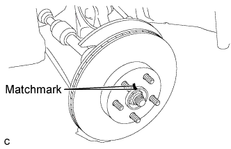
INSTALL FRONT AXLE ASSEMBLY LH
-
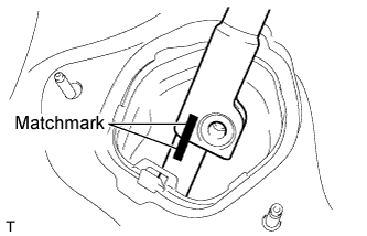
Text in Illustration *a Matchmark Align the matchmarks and connect the front drive shaft assembly to the front axle assembly LH.
-
-
INSTALL FRONT AXLE ASSEMBLY RH
Tech Tips
Perform the same procedure as for the LH side.
-
INSTALL FRONT STABILIZER LINK ASSEMBLY LH
-
Install the front stabilizer link assembly to the front shock absorber with coil spring with the nut.
- Torque:
- 74 N*m { 755 kgf*cm, 55 ft.*lbf }
Note
If the ball joint turns together with the nut, use a hexagon wrench (6 mm) to hold the stud bolt.
-
-
INSTALL FRONT STABILIZER LINK ASSEMBLY RH
Tech Tips
Perform the same procedure as for the LH side.
-
INSTALL NO. 1 FRONT LOWER SUSPENSION ARM SUB-ASSEMBLY LH
-
Connect the front lower suspension arm sub-assembly to the front lower ball joint with the bolt and 2 nuts.
- Torque:
- 93 N*m { 948 kgf*cm, 69 ft.*lbf }
-
-
INSTALL NO. 1 FRONT LOWER SUSPENSION ARM SUB-ASSEMBLY RH
Tech Tips
Perform the same procedure as for the LH side.
-
INSTALL FRONT DISC (for LH Side)
-
Align the matchmarks of the disc and axle hub, and install the disc.
Note
When installing a new disc, select the installation position where the front disc has minimal runout.
-
-
INSTALL FRONT DISC (for RH Side)
Tech Tips
Perform the same procedure as for the LH side.
-
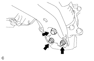
INSTALL FRONT DISC BRAKE CALIPER ASSEMBLY LH
-
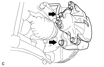
Install the front disc brake caliper assembly to the steering knuckle with the 2 bolts.
- Torque:
- 98 N*m { 999 kgf*cm, 72 ft.*lbf }
-
-
INSTALL FRONT DISC BRAKE CALIPER ASSEMBLY RH
Tech Tips
Perform the same procedure as for the LH side.
-
INSTALL FRONT SPEED SENSOR LH
-
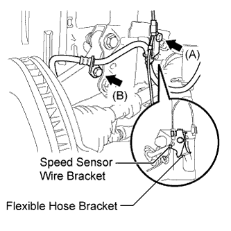
Connect the flexible hose bracket and speed sensor wire bracket with the bolt (A).
- Torque:
- 19 N*m { 194 kgf*cm, 14 ft.*lbf }
Note
Connect the flexible hose bracket first.
-
Connect the flexible hose to the steering knuckle with the bolt (B).
- Torque:
- 19 N*m { 194 kgf*cm, 14 ft.*lbf }
-
Install the front speed sensor to the steering knuckle with the bolt and clamp.
- Torque:
- 8.5 N*m { 87 kgf*cm, 75 in.*lbf }
Note
-
Do not damage the tip of the speed sensor.
-
Make sure that the speed sensor is free of foreign matter.
-
Do not twist the speed sensor wire.
-
-
INSTALL FRONT SPEED SENSOR RH
Tech Tips
Perform the same procedure as for the LH side.
-
INSTALL TIE ROD END SUB-ASSEMBLY LH
-
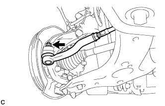
Connect the tie rod end sub-assembly LH to the steering knuckle with the nut.
- Torque:
- 49 N*m { 500 kgf*cm, 36 ft.*lbf }
Note
Further tighten the nut up to 60° if the holes for the cotter pin are not aligned.
-
Install a new cotter pin.
-
-
INSTALL TIE ROD END SUB-ASSEMBLY RH
Tech Tips
Perform the same procedure as for the LH side.
-
INSTALL FRONT AXLE SHAFT NUT LH
-
Clean the threaded parts on the front drive shaft assembly and new front axle shaft nut using a non-residue solvent.
Note
-
Be sure to perform this work for a new drive shaft.
-
Keep the threaded parts free of oil and foreign matter.
-
-
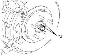
Using a socket wrench (30 mm), while applying the brakes, install the front axle shaft nut.
- Torque:
- for 2GR-FE
- 292 N*m { 2978 kgf*cm, 215 ft.*lbf }
- for 2AZ-FE
- 216 N*m { 2203 kgf*cm, 159 ft.*lbf }
Tech Tips
Tighten the axle shaft nut while the brakes are applied to prevent the front axle from rotating.
-
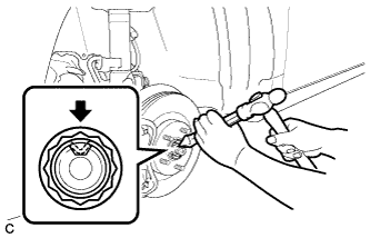
Using a chisel and hammer, stake the front axle shaft nut.
-
-
INSTALL FRONT AXLE SHAFT NUT RH
Tech Tips
Perform the same procedure as for the LH side.
-
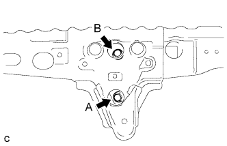
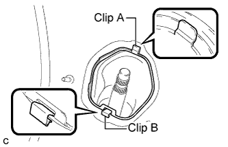
INSTALL NO. 1 STEERING COLUMN HOLE COVER SUB-ASSEMBLY
-
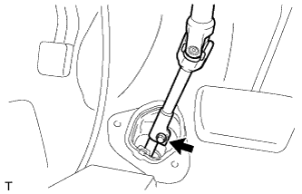
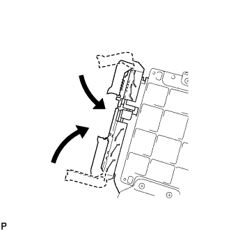
Place clip A as shown in the illustration and engage clip B to the body to connect the No. 1 steering column hole cover sub-assembly.
Note
Make sure that the lip of the No. 1 steering column hole cover sub-assembly is not damaged.
-
-
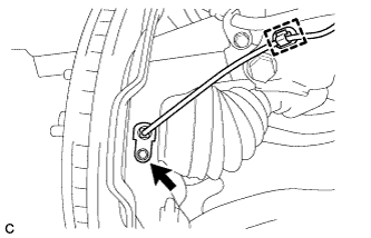
INSTALL NO. 2 STEERING INTERMEDIATE SHAFT ASSEMBLY
-
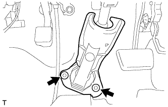
Align the matchmarks on the No. 2 steering intermediate shaft assembly and the steering intermediate shaft assembly.
-
Connect the No. 2 steering intermediate shaft assembly to the steering intermediate shaft assembly, and install the bolt.
- Torque:
- 35 N*m { 360 kgf*cm, 26 ft.*lbf }
-
-
INSTALL COLUMN HOLE COVER SILENCER SHEET
-
Install the column hole cover silencer sheet with the 2 clips.
-
-
INSTALL FRONT EXHAUST PIPE ASSEMBLY
-
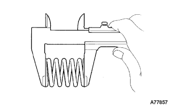
Using a vernier caliper, measure the free length of the compression springs.
Minimum length 41.5 mm (1.64 in.) If the free length is less than the minimum, replace the compression spring.
-
Fully insert a new gasket to the exhaust manifold converter sub-assembly.
-
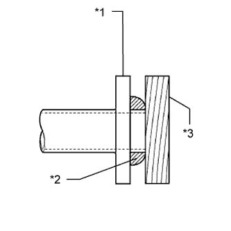
Text in Illustration *1 Exhaust Manifold Converter Sub-assembly *2 Gasket *3 Wooden Block Using a plastic hammer and wooden block, tap in the new gasket until its surface is flush with the exhaust manifold converter sub-assembly.
Note
-
Be sure to install the gasket in the correct direction.
-
Do not reuse the gasket.
-
Do not damage the gasket.
-
Do not push in the gasket by using the exhaust pipe when connecting it.
-
-
Install a new gasket to the front exhaust pipe assembly.
-
Install the front exhaust pipe assembly with the 4 bolts and 2 compression springs.
- Torque:
- 43 N*m { 440 kgf*cm, 32 ft.*lbf }
-
Connect the oxygen sensor connector.
-
-
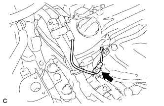
INSTALL FUEL TUBE SUB-ASSEMBLY
-
Push in the fuel tube connector to the fuel main tube until the fuel tube connector makes a "click" sound.
Note
-
Check that there is no damage or foreign matter on the fuel pipe connectors.
-
After connecting, check that the fuel tube connector and the pipe are securely connected by pulling on them.
-
-
Close the No. 1 EFI fuel pipe clamp cover.
Tech Tips
The half connection prevention connector prevents the fuel hose connector cover from being locked if the fuel tube is not securely connected.
-
-
INSTALL COMPRESSOR ASSEMBLY WITH PULLEY
-
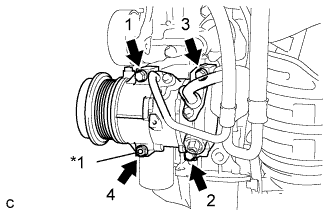
Text in Illustration *1 Stud Bolt Using an E8 "TORX" socket wrench, temporarily install the compressor assembly with pulley with the stud bolt.
- Torque:
- 10 N*m { 102 kgf*cm, 7 ft.*lbf }
-
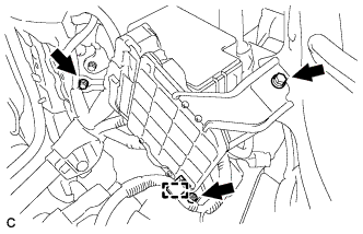
Install the compressor assembly with pulley with the 3 bolts and nut.
Tech Tips
Tighten the bolts and nut in the order indicated in the illustration.
- Torque:
- 25 N*m { 255 kgf*cm, 18 ft.*lbf }
-
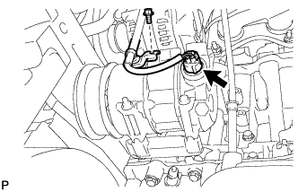
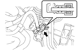
Connect the connector.
-
Install the bracket with the bolt.
-
-
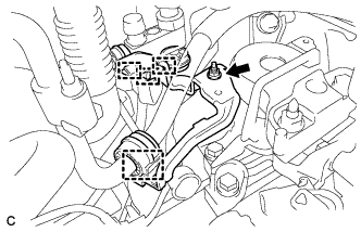
CONNECT WIRE HARNESS
-
Connect the ground cable.
-
Install the ground cable to the transaxle with the bolt and clamp.
- Torque:
- 8.4 N*m { 85 kgf*cm, 74 in.*lbf }
-
Install the ground cable with the bolt and clamp.
-
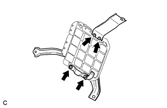
Install the wire harness protector to the bracket with the bolt and 3 clamps.
-
Connect the engine wire to the engine room relay block.
-
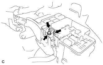
Lock the 2 claws and install the bolt.
- Torque:
- 8.4 N*m { 85 kgf*cm, 74 in.*lbf }
-
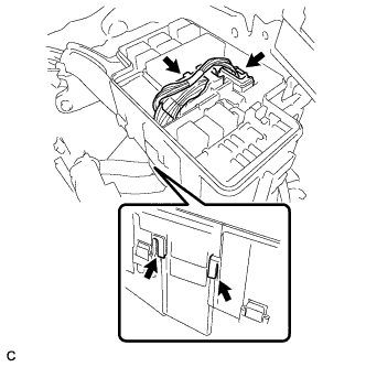
Connect the 2 connectors and 2 claws to the engine room relay block.
-
Install the engine room relay block cover.
-
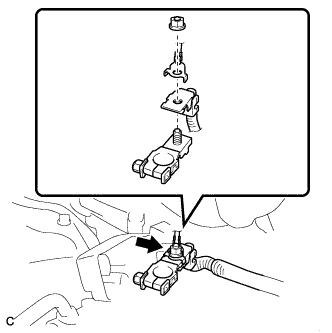
Install the positive (+) battery cable with the nut.
- Torque:
- 7.6 N*m { 77 kgf*cm, 67 in.*lbf }
-
-
INSTALL ECM
-
Install the 2 ECM brackets onto the ECM with the 4 screws.
- Torque:
- 3.0 N*m { 31 kgf*cm, 27 in.*lbf }
-
Connect the 2 ECM connectors and lower the 2 levers.
Note
-
When connecting the connectors, make sure that dirt, water or other foreign matter does not get caught between the connectors and other parts.
-
Make sure that the 2 levers are securely locked.
-
-
Install the ECM with the 3 bolts.
- Torque:
- 5.5 N*m { 56 kgf*cm, 49 in.*lbf }
-
Connect the wire harness clamp.
-
-
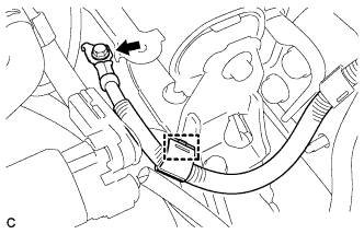
INSTALL TRANSMISSION CONTROL CABLE ASSEMBLY
-
Connect the transmission control cable assembly to the control shaft lever with the nut.
- Torque:
- 12 N*m { 122 kgf*cm, 9 ft.*lbf }
-
Connect the transmission control cable assembly to the control cable bracket with a new clip.
-
Connect the transmission control cable assembly to the control cable bracket.
-
-
CONNECT UNION TO CHECK VALVE HOSE
-
Connect the union to check valve hose.
-
-
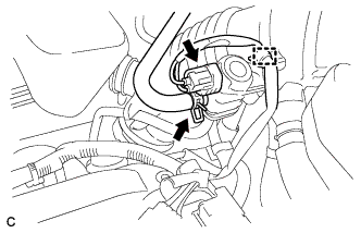
CONNECT INLET OIL COOLER HOSE (for CVT)
-
w/ Air Cooled Transmission Oil Cooler:
-
Connect the inlet oil cooler hose to the oil cooler outlet tube.
-
-
-
CONNECT OUTLET NO. 1 OIL COOLER HOSE (for CVT)
-
w/ Air Cooled Transmission Oil Cooler:
-
Connect the outlet No. 1 oil cooler hose to the oil cooler outlet tube.
-
-
-
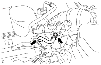
CONNECT NO. 6 WATER BY-PASS HOSE (for CVT)
-
w/ Air Cooled Transmission Oil Cooler:
-
Connect the No. 6 water by-pass hose to the No. 4 water by-pass pipe.
-
-
-
CONNECT OIL COOLER HOSE (for Automatic Transaxle)
-
Connect the 2 oil cooler hoses to the automatic transaxle.
-
-
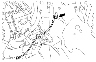
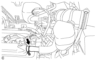
CONNECT WATER BY-PASS HOSE
-
Connect the 2 water by-pass hoses.
-
-
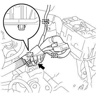
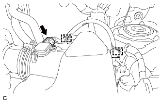
CONNECT BREATHER PLUG HOSE
-
Connect the breather plug hose.
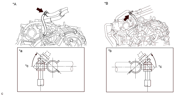
Text in Illustration *A for Automatic Transaxle
for CVT (w/ Air Cooled Transmission Oil Cooler)
*B for CVT (w/o Air Cooled Transmission Oil Cooler) *a View from Side of the Vehicle *b View from Front of the Vehicle *c Horizontal Axis - - Note
-
Make sure that the marking on the water by-pass hose is aligned with the center of the clamp.
-
Make sure that the breather plug hose is positioned on the left side of the vehicle.
-
Make sure that the breather plug is inclined as shown in the illustration.
-
Make sure that the hose is not kinked.
-
-
-
INSTALL NO. 1 RADIATOR HOSE
-
Connect the No. 1 radiator hose.
-
Connect the wire clamp.
-
-
INSTALL NO. 2 RADIATOR HOSE
-
Connect the No. 2 radiator hose.
-
-
INSTALL GENERATOR ASSEMBLY
-
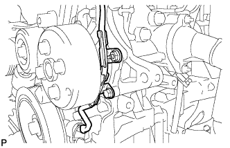
Confirm that the wire harness of the crankshaft position sensor is secured to the wire harness clamp bracket through the back of the rib of the timing chain cover.
-
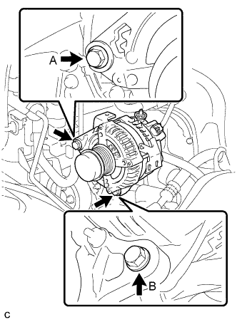
Install the generator assembly with the 2 bolts.
- Torque:
- Bolt A
- 52 N*m { 530 kgf*cm, 38 ft.*lbf }
- Bolt B
- 21 N*m { 214 kgf*cm, 15 ft.*lbf }
-
Install the generator wire to terminal B with the nut.
- Torque:
- 9.8 N*m { 100 kgf*cm, 88 in.*lbf }
-
Install the clamp bracket with the bolt.
- Torque:
- 7.7 N*m { 79 kgf*cm, 68 in.*lbf }
-
Attach the clamp and connect the generator connector to the generator.
-
-
INSTALL V-RIBBED BELT
-
When reusing the V-ribbed belt tensioner:
-
Install the V-ribbed belt Click here.
-
-
When replacing the V-ribbed belt tensioner with a new one:
-
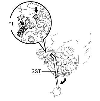
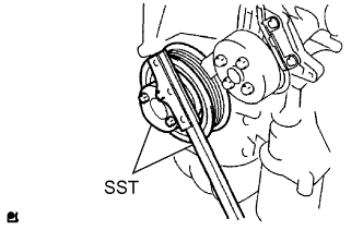
Text in Illustration *1 Pin Using SST, slowly rotate the V-ribbed belt tensioner clockwise to compress it.
- SST
- 09216-42010
-
Pull out the pin from the V-ribbed belt tensioner while the V-ribbed belt tensioner is compressed.
-
Slowly return the V-ribbed belt tensioner.
Note
-
Make sure that SST and other tools are set to the tensioner securely.
-
When compressing the V-ribbed belt tensioner, slowly rotate the tensioner.
-
-
Install the V-ribbed belt Click here.
-
-
-
INSTALL RADIATOR RESERVE TANK BRACKET
-
Install the radiator reserve tank bracket with the 2 bolts.
- Torque:
- 12 N*m { 122 kgf*cm, 9 ft.*lbf }
-
-
INSTALL RADIATOR RESERVE TANK ASSEMBLY
-
Install the radiator reserve tank assembly to the radiator reserve tank bracket.
- Torque:
- 12 N*m { 122 kgf*cm, 9 ft.*lbf }
-
Connect the No. 1 and No. 2 water by-pass hoses.
-
Connect the wire harness clamp to the radiator reserve tank assembly.
-
-
INSTALL BATTERY CARRIER SUPPORT
-
Install the battery carrier support with the 2 bolts.
- Torque:
- 20 N*m { 204 kgf*cm, 15 ft.*lbf }
-
-
INSTALL BATTERY CARRIER
-
Install the battery carrier with the 4 bolts.
- Torque:
- 20 N*m { 204 kgf*cm, 15 ft.*lbf }
-
Attach the 2 wire harness clamps.
-
-
INSTALL BATTERY TRAY
-
Install the battery tray.
-
-
INSTALL NO. 2 AIR CLEANER INLET
-
Install the No. 2 air cleaner inlet with the bolt.
- Torque:
- 8.0 N*m { 82 kgf*cm, 71 in.*lbf }
-
-
INSTALL AIR CLEANER CASE
-
Install the air cleaner case with the 3 bolts.
- Torque:
- 7.0 N*m { 71 kgf*cm, 62 in.*lbf }
-
Install the engine wire clamp to the air cleaner case.
-
Install the air cleaner filter element.
-
-
INSTALL AIR CLEANER CAP SUB-ASSEMBLY WITH HOSE
-
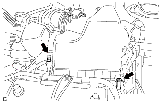
Install the air cleaner cap sub-assembly with hose and lock the 2 clamps.
-
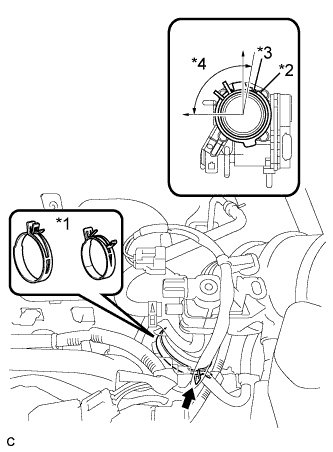
Text in Illustration *1 No. 1 air cleaner hose clamp *2 Groove *3 Tab *4 95° Connect the No. 1 air cleaner hose to the throttle body and release the lock of the No. 1 air cleaner hose clamp.
Note
-
Align the groove of the air cleaner hose with the tab of the throttle body and install the hose.
-
Make sure that the tab of the No. 1 air cleaner hose clamp stays within the range shown by *4
-
-
Connect the 2 wire harness clamps and the mass air flow meter connector.
-
Connect the ventilation hose.
-
Connect the purge line hose to the No. 1 vacuum switching valve assembly and air cleaner hose.
-
Connect the fuel vapor feed hose to the No. 1 vacuum switching valve assembly.
-
Connect the wire harness clamp and No. 1 vacuum switching valve connector.
-
-
INSTALL BATTERY
-
Install the battery and battery insulator.
-
Install the battery clamp with the bolt and nut.
- Torque:
- Bolt
- 46 N*m { 469 kgf*cm, 34 ft.*lbf }
- Nut
- 4.9 N*m { 50 kgf*cm, 43 in.*lbf }
-
Connect the 2 wire harness clamps.
-
Connect the positive (+) cable to the positive (+) battery terminal.
- Torque:
- 5.4 N*m { 55 kgf*cm, 48 in.*lbf }
-
-
INSTALL OUTER COWL TOP PANEL SUB-ASSEMBLY
-
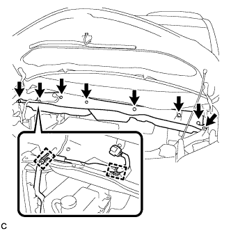
Install the outer cowl top panel with the 8 bolts.
- Torque:
- 8.8 N*m { 90 kgf*cm, 78 in.*lbf }
-
Connect the 2 clamps to the outer cowl top panel.
-
Remove the protective tape.
-
-
INSTALL BRAKE MASTER CYLINDER RESERVOIR ASSEMBLY
-
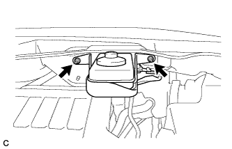
Install the brake master cylinder reservoir with bracket to the outer cowl top panel with the 2 nuts.
- Torque:
- 6.5 N*m { 66 kgf*cm, 58 in.*lbf }
-
-
INSTALL WINDSHIELD WIPER MOTOR AND LINK
-
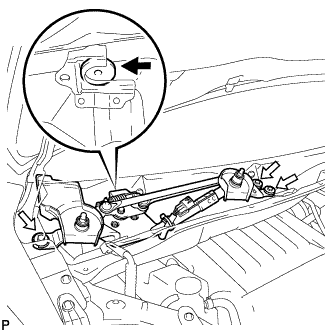
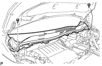
Install the windshield wiper motor and link assembly with the 3 bolts as shown in the illustration.
- Torque:
- 5.5 N*m { 56 kgf*cm, 49 in.*lbf }
-
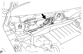
Connect the connector.
-
-
INSTALL COWL TOP VENTILATOR LOUVER SUB-ASSEMBLY
-
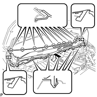
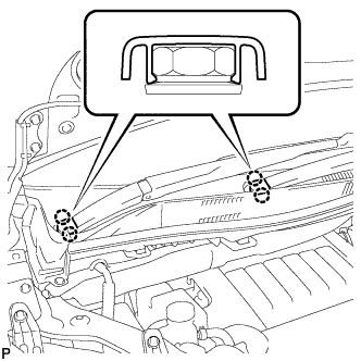
Engage the 15 claws and 2 guides to install the cowl top ventilator louver sub-assembly as shown in the illustration.
-
Install the 2 clips.
-
-
INSTALL WINDSHIELD WIPER ARM AND BLADE ASSEMBLY RH
-
Operate the wiper and stop the windshield wiper motor at the automatic stop position.
-
When reusing the front wiper arm and blade assembly RH:
-
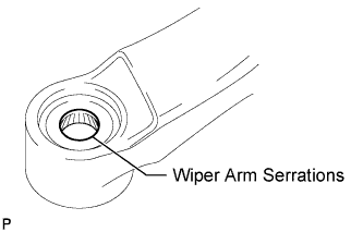
Clean the wiper arm serrations.
-
-
When reusing the windshield wiper link assembly:
-
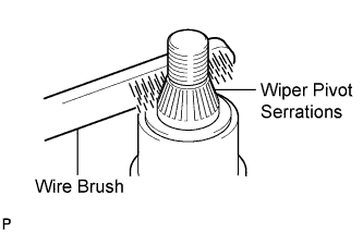
Clean the wiper pivot serrations with a wire brush.
-
-
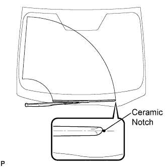
Install the front wiper arm and blade assembly RH with the nut to the position shown in the illustration.
- Torque:
- 24 N*m { 245 kgf*cm, 18 ft.*lbf }
-
-
INSTALL WINDSHIELD WIPER ARM AND BLADE ASSEMBLY LH
-
When reusing the front wiper arm and blade assembly LH:
-
Clean the wiper arm serrations.
-
-
When reusing the windshield wiper link assembly:
-
Clean the wiper pivot serrations with a wire brush.
-
-
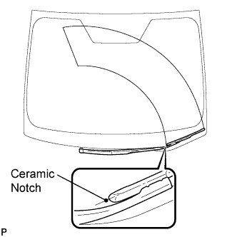
Install the front wiper arm and blade assembly LH with the nut to the position shown in the illustration.
- Torque:
- 24 N*m { 245 kgf*cm, 18 ft.*lbf }
-
Operate the front wipers while spraying washer fluid onto the windshield. Make sure that the front wipers function properly and the wipers do not come into contact with the vehicle body.
-
-
INSTALL WINDSHIELD WIPER ARM COVER
-
Engage the 2 claws to install the 2 windshield wiper arm covers.
-
-
INSPECT SHIFT LEVER POSITION
-
ADJUST SHIFT LEVER POSITION
-
CONNECT CABLE FROM NEGATIVE BATTERY TERMINAL
-
Connect the negative (-) battery terminal.
- Torque:
- 5.4 N*m { 55 kgf*cm, 48 in.*lbf }
Note
When disconnecting the cable, some systems need to be initialized after the cable is reconnected Click here.
-
-
ADD ENGINE COOLANT
-
Tighten the radiator drain cock plug by hand.
-
Tighten the cylinder block drain cock plug.
- Torque:
- 13 N*m { 130 kgf*cm, 9 ft.*lbf }
-
Remove the reserve tank cap. (*1)
-
Add TOYOTA Super Long Life Coolant (SLLC).
Standard capacity 8.6 liters (9.1 US qts, 7.6 Imp. qts) Note
Never use water as a substitute for engine coolant.
Tech Tips
-
TOYOTA vehicles are filled with TOYOTA SLLC at the factory. In order to avoid damage to the engine cooling system and other technical problems, only use TOYOTA SLLC or similar high quality ethylene glycol based non-silicate, non-amine, non-nitrite, non-borate coolant with long-life hybrid organic acid technology (coolant with long-life hybrid organic acid technology is a combination of low phosphates and organic acids).
-
Squeeze the No. 1 and No. 2 radiator hoses several times. If the coolant level at the water inlet opening drops, add TOYOTA SLLC.
-
-
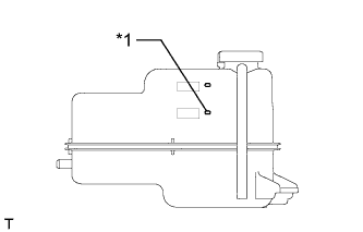
Text in Illustration *1 B Line Continue adding TOYOTA SLLC until it reaches the B line. (*2)
-
Install the reserve tank cap. (*3)
-
Run the engine at about 2000 rpm to warm it up until the thermostat opens. While the thermostat is open, circulate the coolant for several minutes. (*4)
CAUTION:
-
When pushing the radiator hoses, wear protective gloves.
-
Be careful as the radiator hoses, engine and radiator are hot.
-
Keep your hands away from the radiator fans.
Note
-
If the radiator reserve tank runs out of coolant just after the engine is started, stop the engine immediately, wait until the coolant has cooled down, and then add coolant.
-
Make sure that the reserve tank still has some coolant in it.
-
If the coolant temperature gauge indicates an excessive temperature, turn off the engine and let it cool.
-
If there is not enough coolant, the engine may overheat or be seriously damaged.
-
-
Stop the engine and wait until the coolant cools down. (*5)
-
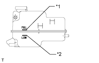
Text in Illustration *1 Full Line *2 Low Line Check that the coolant level is between the full and low lines. (*6)
Tech Tips
-
If the coolant level is below the low line, repeat steps from (*1) to (*6).
-
If the coolant level is above the full line, drain coolant so that the coolant level is between the full and low lines.
-
-
-
ADD ENGINE OIL
-
Clean and install the oil drain plug with a new gasket.
- Torque:
- 40 N*m { 408 kgf*cm, 29 ft.*lbf }
-
Add new engine oil.
Standard Oil Grade Oil Grade Oil Viscosity (SAE) API grade SL "Energy-Conserving", SM "Energy-Conserving", SN "Resource-Conserving" or ILSAC multigrade engine oil
-
0W-20
-
5W-20
-
5W-30
-
10W-30
API grade SL, SM or SN multigrade engine oil
-
15W-40
-
20W-50
Standard Oil Grade (Destination package for Philippines) Oil Grade Oil Viscosity (SAE) API grade SL "Energy-Conserving", SM "Energy-Conserving", SN "Resource-Conserving" or ILSAC multigrade engine oil
-
5W-30
-
10W-30
API grade SL, SM or SN multigrade engine oil
-
15W-40
-
20W-50
Standard Oil Capacity Item Standard Condition Drain and refill with oil filter change 4.3 liters (4.5 US qts, 3.8 Imp. qts) Drain and refill without oil filter change 4.1 liters (4.3 US qts, 3.6 Imp. qts) Dry fill 5.0 liters (5.3 US qts, 4.4 Imp. qts) -
-
Install the oil filler cap.
-
-
ADD AUTOMATIC TRANSAXLE FLUID (for Automatic Transaxle)
Fluid type Toyota Genuine ATF WS -
INSPECT AUTOMATIC TRANSAXLE FLUID LEVEL (for Automatic Transaxle)
Tech Tips
Drive the vehicle so that the engine and transaxle are at normal operating temperature.
Fluid temperature 70 to 80°C (158 to 176°F)
-
Park the vehicle on a level surface and apply the parking brake.
-
With the engine idling and the brake pedal depressed, move the shift lever to all positions from P to L. Then return it to P.
-
Pull out the ATF dipstick and wipe it clean.
-
Fully push the dipstick back into the pipe.
-
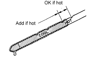
Pull the dipstick out again and check that the fluid level is at the HOT position.
If there are leaks, it is necessary to repair or replace O-rings, FIPGs, oil seals, plugs and/or other parts.
CAUTION:
Wear gloves when working.
-
-
ADD CONTINUOUSLY VARIABLE TRANSAXLE FLUID (for CVT)
Tech Tips
-
WARM UP ENGINE
-
INSPECT FOR FUEL LEAK
-
Check fuel pump operation.
-
Connect the intelligent tester to the DLC3.
-
Turn the engine switch on (IG) and turn the intelligent tester on.
Note
Do not start the engine.
-
Enter the following menus: Powertrain / Engine / Active Test / Control the Fuel Pump / Speed.
-
Check for pressure in the fuel inlet tube from the fuel line. Check that sounds of fuel flowing in the fuel tank can be heard. If no sounds can be heard, check the integration relay, fuel pump, ECM and wiring connectors.
-
-
Inspect for fuel leaks.
-
Check that there is no fuel leakage after performing maintenance anywhere on the fuel system. If there is a fuel leak, repair or replace parts if necessary.
-
-
Turn the engine switch off.
-
Disconnect the intelligent tester from the DLC3.
-
-
INSPECT FOR COOLANT LEAK
-
Remove the radiator reservoir cap.
CAUTION:
Do not remove the radiator reservoir cap while the engine and radiator are still hot. Pressurized, hot engine coolant and steam may be released and cause serious burns.
-
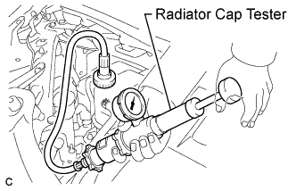
Fill the radiator and reservoir with coolant, and then attach a radiator cap tester.
-
Warm up the engine.
-
Pump the radiator cap tester to 118 kPa (1.2 kgf/cm2, 17 psi), and then check that the pressure does not drop.
If the pressure drops, check the hoses, radiator and water pump for leaks.
If there are no signs of external coolant leaks, check the heater core, cylinder block and head.
-
Reinstall the radiator reservoir cap.
-
-
INSPECT FOR OIL LEAK
-
INSPECT FOR EXHAUST GAS LEAK
-
INSTALL REAR ENGINE UNDER COVER LH
-
INSTALL REAR ENGINE UNDER COVER RH
-
INSTALL NO. 2 ENGINE UNDER COVER (for Rear Side)
-
INSTALL NO. 2 ENGINE UNDER COVER (for Front Side)
-
INSTALL ENGINE UNDER COVER
-
INSTALL NO. 1 ENGINE UNDER COVER
-
INSTALL RADIATOR COVER SUB-ASSEMBLY
-
Install the radiator cover sub-assembly with the 4 clips.
-
-
INSTALL FRONT WHEELS
- Torque:
- 103 N*m { 1050 kgf*cm, 76 ft.*lbf }
-
INSPECT IGNITION TIMING
Note
-
Turn all the electrical systems and the A/C off.
-
When checking the ignition timing, the transaxle should be in neutral or park.
-
Warm up and stop the engine.
-
When using the intelligent tester:
-
Connect the intelligent tester to the DLC3.
-
Turn the engine switch on (IG).
-
Turn the intelligent tester on.
-
Enter the following menus: Power Train / Engine and ECT / Data List / IGN Advance
-
Start the engine.
-
According to the display on the intelligent tester, read the Data List.
Standard ignition timing 8 to 16° BTDC at idle -
Check that the ignition timing advances immediately when the engine speed is increased.
-
Turn the engine switch off.
-
Disconnect the intelligent tester from the DLC3.
-
-
When not using the intelligent tester:
-
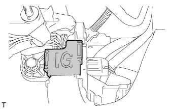
Open the ignition cover located to the right of the No. 4 ignition coil.
-
Pull the wire harness out from the IG cover.
-
Connect the timing light to the wire harness.
Note
Use a timing light that detects the primary signal.
-
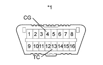
Text in Illustration *1 DLC3 Using SST, connect terminals 13 (TC) and 4 (CG) of the DLC3.
- SST
- 09843-18040
-
Allow the engine to idle and check the ignition timing.
Standard ignition timing 8 to 12° BTDC at idle Tech Tips
Run the engine at 1000 to 1300 rpm for 5 seconds, then check that the engine speed returns to idle speed.
-
Disconnect SST from terminals 13 (TC) and 4 (CG) of the DLC3.
-
Allow the engine to idle and check the ignition timing.
Standard ignition timing 8 to 16° BTDC at idle -
Check that the ignition timing advances immediately when the engine speed is increased.
-
Turn the engine switch off.
-
Remove the timing light.
-
Close the IG cover.
-
-
-
INSPECT ENGINE IDLING SPEED
Note
-
Turn all the electrical systems and the A/C off.
-
When checking the idle speed, the transaxle should be in neutral or park.
-
Warm up and stop the engine.
-
When using the intelligent tester:
-
Connect the intelligent tester to the DLC3.
-
Turn the engine switch on (IG).
-
Turn the intelligent tester on.
-
Enter the following menus: Power Train / Engine and ECT / Data List / Engine Speed
-
Start the engine.
-
According to the display on the intelligent tester, read the Data List.
Standard idle speed 670 to 770 rpm -
Turn the engine switch off.
-
Disconnect the intelligent tester from the DLC3.
-
-
When not using the intelligent tester:
-
Turn off all the accessories and air conditioning.
-
Move the shift lever to P or N.
-
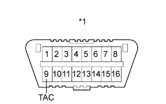
Text in Illustration *1 DLC3 Connect SST to 9 (TAC) of the DLC3 terminal, and then connect a tachometer to SST.
- SST
- 09843-18030
-
Start the engine.
-
Check the idle speed with the cooling fans off.
Standard idle speed 670 to 770 rpm -
Turn the engine switch off.
-
Remove the tachometer and disconnect SST from the DLC3.
-
-
-
INSPECT CO/HC
Tech Tips
This check determines whether or not the idle CO/HC complies with local regulations.
-
Start and warm up the engine.
-
Run the engine at 2500 rpm for approximately 180 seconds.
-
Insert the CO/HC meter testing probe at least 40 cm (1.3 ft.) into the tailpipe while idling.
-
Inspect the CO/HC concentration during idle at 2500 rpm.
If the CO/HC concentration does not comply with local regulations, troubleshoot in the order given below.
-
Check the A/F sensor and heated oxygen sensor operation.
-
See the table below for possible causes, then inspect the applicable parts and repair them if necessary.
CO HC Problem Possible Cause Normal High Rough idle 1. Faulty ignition:
- Incorrect timing
- Plugs are contaminated, shorted, or gaps are defective
2. Incorrect valve clearance
3. Leaks in intake and exhaust valve
4. Leaks in cylinders
Low High Rough idle
(Fluctuating HC reading)
1. Vacuum leakage:
- Ventilation hoses
- Intake manifold
- Throttle body
- Brake booster line
2. Lean mixture causing misfire
High High Rough idle
(Black smoke from exhaust)
1. Restricted air filter
2. Plugged PCV valve
3. Faulty EFI system:
- Faulty pressure regulator
- Faulty engine coolant temperature sensor
- Faulty mass air flow meter
- Faulty ECM
- Faulty injectors
- Faulty throttle body
-
-
-
ADJUST FRONT WHEEL ALIGNMENT
-
CHECK ABS SPEED SENSOR SIGNAL