CAMSHAFT REMOVAL

-
DISCONNECT CABLE FROM NEGATIVE BATTERY TERMINAL
Note
When disconnecting the cable, some systems need to be initialized after the cable is reconnected Click here.
-
REMOVE FRONT WHEELS RH
-
REMOVE REAR ENGINE UNDER COVER RH
-
DRAIN ENGINE OIL
-
Remove the oil filler cap.
-
Remove the oil drain plug and gasket, and drain the engine oil into a container.
-
-
REMOVE WINDSHIELD WIPER ARM COVER
-
Using a screwdriver, disengage the 2 claws and remove the 2 windshield wiper arm covers.
Tech Tips
Tape the screwdriver tip before use.
-
-
REMOVE WINDSHIELD WIPER ARM AND BLADE ASSEMBLY LH
-
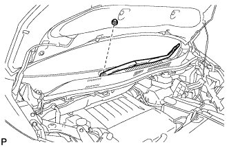
Remove the nut and the front wiper arm and blade assembly LH.
-
-
REMOVE WINDSHIELD WIPER ARM AND BLADE ASSEMBLY RH
-
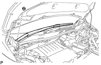
Remove the nut and the front wiper arm and blade assembly RH.
-
-
REMOVE COWL TOP VENTILATOR LOUVER SUB-ASSEMBLY
-
Remove the 2 clips.
-
Disengage the 15 claws and 2 guides, and remove the cowl top ventilator louver sub-assembly as shown in the illustration.
-
-
REMOVE WINDSHIELD WIPER MOTOR AND LINK
-
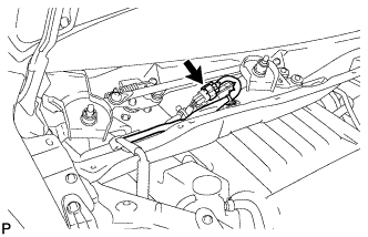
Disconnect the connector.
-
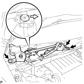
Remove the 3 bolts and the windshield wiper motor and link assembly as shown in the illustration.
-
-
REMOVE BRAKE MASTER CYLINDER RESERVOIR ASSEMBLY
-
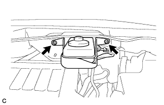
Remove the 2 nuts and separate the brake master cylinder reservoir with bracket from the outer cowl top panel.
-
-
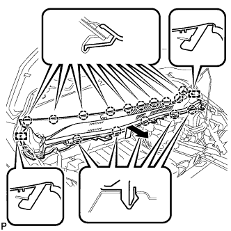
REMOVE OUTER COWL TOP PANEL SUB-ASSEMBLY
-
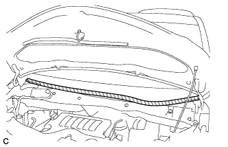
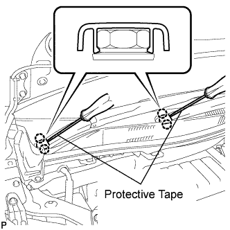
Apply protective tape as shown in the illustration.
Text in Illustration 
Protective Tape -
Disconnect the 2 clamps from the outer cowl top panel.
-
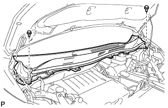
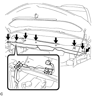
Remove the 8 bolts.
-
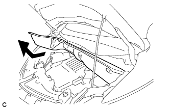
Remove the outer cowl top panel as shown in the illustration.
-
-
REMOVE RADIATOR COVER SUB-ASSEMBLY
-
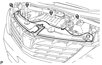
Using a clip remover, remove the 4 clips and radiator cover sub-assembly.
-
-
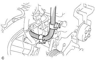
REMOVE RADIATOR RESERVE TANK ASSEMBLY
-
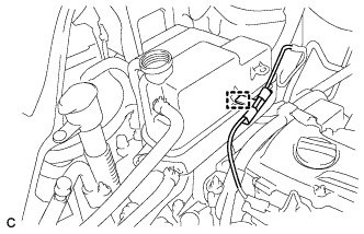
Disconnect the wire clamp.
-
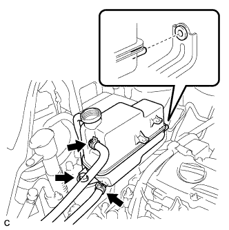
Disconnect the No. 1 and No. 2 water by-pass hoses.
-
Remove the bolt and radiator reserve tank assembly.
-
-
REMOVE RADIATOR RESERVE TANK BRACKET
-
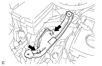
Remove the 2 bolts and radiator reserve tank bracket.
-
-
REMOVE IGNITION COIL ASSEMBLY
-
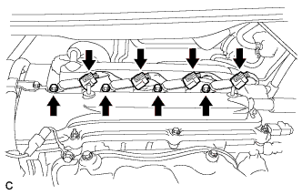
Disconnect the 4 ignition coil connectors.
-
Remove the 4 bolts and 4 ignition coils.
-
-
REMOVE SPARK PLUG
-
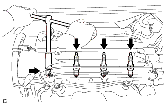
Remove the 4 spark plugs.
-
-
REMOVE CYLINDER HEAD COVER SUB-ASSEMBLY
-
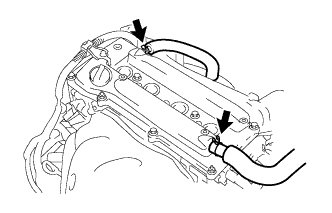
Remove the 2 ventilation hoses from the cylinder head cover sub-assembly.
-
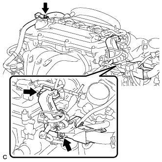
Remove the 3 bolts and separate the wire harness.
-
Disconnect the 2 wire harness clamps.
-
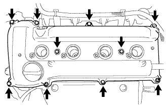
Remove the 8 bolts and 2 nuts, then remove the cylinder head cover sub-assembly and gasket.
-
-
SET NO. 1 CYLINDER TO TDC/COMPRESSION
-
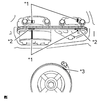
Text in Illustration *1 Timing Mark *2 Paint Mark *3 Groove Turn the crankshaft pulley until the groove and the timing mark "0" on the timing chain cover are aligned.
-
Check that each timing mark on the camshaft timing gear and sprocket is aligned with each timing mark located on the No. 1 and No. 2 bearing caps as shown in the illustration.
If not, turn the crankshaft pulley 1 revolution (360°) to align the timing marks as illustrated.
-
Place paint marks on the chain in alignment with the timing marks on the camshaft timing gear and camshaft timing sprocket.
-
-
REMOVE NO. 1 CHAIN TENSIONER ASSEMBLY
-
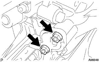
Remove the 2 nuts and No. 1 chain tensioner assembly.
Note
Do not turn the crankshaft without the No. 1 chain tensioner assembly.
-
-
LOOSEN CAMSHAFT TIMING GEAR OR SPROCKET
-
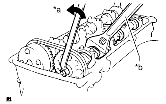
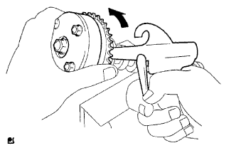
Text in Illustration *a Loosen *b Hold While holding the No. 2 camshaft with a wrench, loosen the No. 2 camshaft timing set bolt.
-
-
REMOVE NO. 2 CAMSHAFT
-
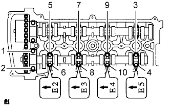
Using several steps, uniformly loosen and remove the 10 bearing cap bolts in the sequence shown in the illustration.
-
Remove the 5 bearing caps.
-
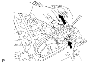
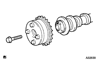
While holding the No. 2 camshaft by hand, remove the camshaft timing sprocket set bolt.
-
Remove the camshaft timing sprocket from the No. 2 camshaft with the timing chain wrapped on the sprocket.
-
Remove the camshaft timing sprocket from the timing chain.
-
-
REMOVE CAMSHAFT
-
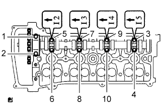
In several steps, uniformly loosen and remove the 10 bearing cap bolts in the sequence shown in the illustration.
-
Remove the 5 bearing caps.
-
Remove the camshaft and camshaft timing gear assembly while holding the timing chain by hand.
-
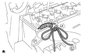
Support the timing chain with a string to prevent it from slipping off the crankshaft sprocket as shown in the illustration.
Note
Be careful not to drop anything inside the timing chain cover.
-
-
REMOVE CAMSHAFT TIMING GEAR ASSEMBLY
-
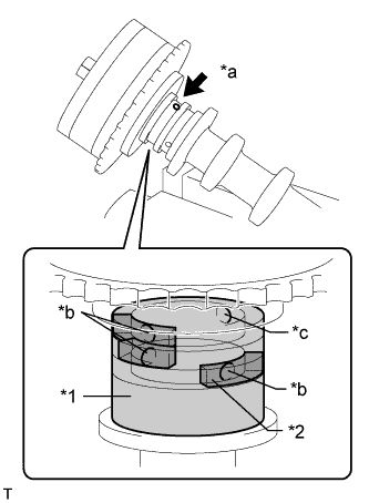
Text in Illustration *1 Vinyl Tape *2 Rubber *a Advance Side Path *b Close *c Open Clamp the camshaft in a vise, and make sure that the camshaft timing gear assembly does not rotate.
-
Cover all the oil path with vinyl tape except the advance side path shown in the illustration.
-
Apply air pressure of 150 kPa (1.5 kgf/cm2, 22 psi) to the oil path, then turn the camshaft timing gear assembly to the advance direction (counterclockwise) by hand.
CAUTION:
Cover the paths with a piece of cloth to avoid oil splashes.
Tech Tips
Depending on the air pressure, the camshaft timing gear assembly may turn to the advance side without applying force by hand. Also, if the pressure is difficult to apply because of air leakage from a path, the lock pin may be difficult to release.
-
Remove the flange bolt and camshaft timing gear.
Note
-
Be sure not to remove the other 4 bolts.
-
When reusing the camshaft timing gear, release the straight pin lock first, then install the gear.
-
-