ECM INSTALLATION

-
INSTALL ECM
-
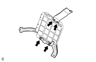
Install the 2 ECM brackets onto the ECM with the 4 screws.
- Torque:
- 3.0 N*m { 31 kgf*cm, 27 in.*lbf }
-
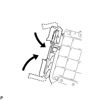
Connect the 2 ECM connectors and lower the 2 levers.
Note
-
When connecting the connectors, make sure that dirt, water or other foreign matter does not get caught between the connectors and other parts.
-
Make sure that the 2 levers are securely locked.
-
-
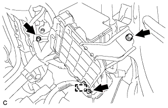
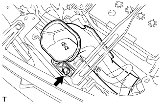
Install the ECM with the 3 bolts.
- Torque:
- 5.5 N*m { 56 kgf*cm, 49 in.*lbf }
-
Connect the wire harness clamp.
-
-
INSTALL AIR CLEANER CASE
-
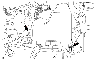
Install the air cleaner case with the 3 bolts.
- Torque:
- 7.0 N*m { 71 kgf*cm, 62 in.*lbf }
-
Install the engine wire clamp to the air cleaner case.
-
Install the air cleaner filter element.
-
-
INSTALL AIR CLEANER CAP AND HOSE
-
Install the air cleaner cap sub-assembly with hose and lock the 2 clamps.
-
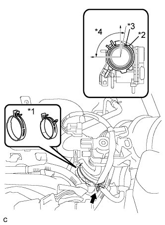
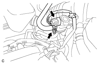
Text in Illustration *1 No. 1 air cleaner hose clamp *2 Groove *3 Tab *4 95° Connect the No. 1 air cleaner hose to the throttle body and release the lock of the No. 1 air cleaner hose clamp.
Note
-
Align the groove of the air cleaner hose with the tab of the throttle body and install the hose.
-
Make sure that the tab of the No. 1 air cleaner hose clamp stays within the range shown by *4
-
-
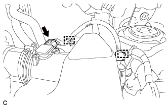
Connect the 2 wire harness clamps and the mass air flow meter connector.
-
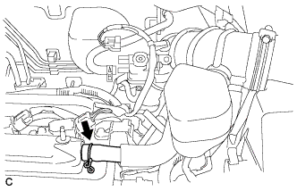
Connect the ventilation hose.
-
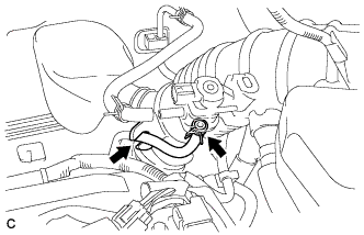
Connect the purge line hose to the No. 1 vacuum switching valve assembly and air cleaner hose.
-
Connect the fuel vapor feed hose to the No. 1 vacuum switching valve assembly.
-
Connect the wire harness clamp and No. 1 vacuum switching valve connector.
-
-
INSTALL NO. 2 AIR CLEANER INLET
-
Install the No. 2 air cleaner inlet with the bolt.
- Torque:
- 8.0 N*m { 82 kgf*cm, 71 in.*lbf }
-
-
INSTALL NO. 1 AIR CLEANER INLET
-
Install the No. 1 air cleaner inlet with the bolt.
- Torque:
- 8.0 N*m { 82 kgf*cm, 71 in.*lbf }
-
-
INSTALL BATTERY CARRIER SUPPORT
-
Install the battery carrier support with the 2 bolts.
- Torque:
- 20 N*m { 204 kgf*cm, 15 ft.*lbf }
-
-
INSTALL BATTERY CARRIER
-
Install the battery carrier with the 4 bolts.
- Torque:
- 20 N*m { 204 kgf*cm, 15 ft.*lbf }
-
Attach the 2 wire harness clamps.
-
-
INSTALL BATTERY TRAY
-
INSTALL BATTERY
-
Install the battery and battery insulator.
-
Install the battery clamp with the bolt and nut.
- Torque:
- Bolt
- 46 N*m { 469 kgf*cm, 34 ft.*lbf }
- Nut
- 4.9 N*m { 50 kgf*cm, 43 in.*lbf }
-
Connect the 2 wire harness clamps.
-
Connect the positive (+) cable to the positive (+) battery terminal.
- Torque:
- 5.4 N*m { 55 kgf*cm, 48 in.*lbf }
-
-
INSTALL OUTER COWL TOP PANEL SUB-ASSEMBLY
-
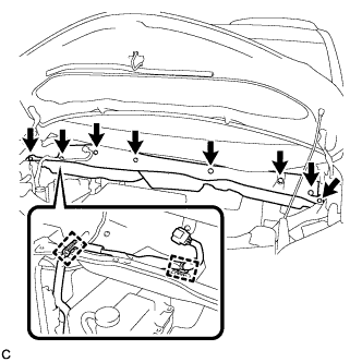
Install the outer cowl top panel with the 8 bolts.
- Torque:
- 8.8 N*m { 90 kgf*cm, 78 in.*lbf }
-
Connect the 2 clamps to the outer cowl top panel.
-
Remove the protective tape.
-
-
INSTALL BRAKE MASTER CYLINDER RESERVOIR WITH BRACKET
-
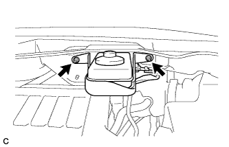
Install the brake master cylinder reservoir with bracket to the outer cowl top panel with the 2 nuts.
- Torque:
- 6.5 N*m { 66 kgf*cm, 58 in.*lbf }
-
-
INSTALL WINDSHIELD WIPER MOTOR AND LINK
-
See the steps from "Install windshield wiper motor and link assembly" through "Install windshield wiper arm cover" Click here.
-
-
CONNECT CABLE TO NEGATIVE BATTERY TERMINAL
Note
When disconnecting the cable, some systems need to be initialized after the cable is reconnected Click here.
-
INSTALL RADIATOR COVER SUB-ASSEMBLY
-
Install the radiator cover sub-assembly with the 4 clips.
-
-
PERFORM INITIALIZATION
Tech Tips
Initialization cannot be completed by only disconnecting and reconnecting the cable of the negative (-) battery terminal.
-
Perform Reset Memory/calibration when replacing the ECM Click here (for K112).
-
Perform Reset Memory/calibration when replacing the ECM Click here (for U241E).
-
Perform Registration (ECU communication ID) when replacing the ECM (See the Service bulletin for the registration method).
-