AIR SUSPENSION SYSTEM, Diagnostic DTC:C1761/61

| DTC Code | DTC Name |
|---|---|
| C1761/61 | Continuous Current to Compressor Motor |
DESCRIPTION
The signal from the suspension control ECU operates the AIR SUS relay and the height control compressor motor starts. The height control compressor motor operates until the targeted vehicle height is reached. Then the height control sensor sends the signal to the suspension control ECU, and stops the height control compressor motor.
| DTC Code | DTC Detection Condition | Trouble Area |
|---|---|---|
| C1761/61 | Either condition is met a total of 2 times or more with the ignition switch ON:
|
|
INSPECTION PROCEDURE
Note
When replacing the suspension control ECU, perform registration Click here.
Tech Tips
If DTC C1782/82 is output at the same time, perform troubleshooting for C1782/82 first Click here.
PROCEDURE
-
CUSTOMER PROBLEM ANALYSIS
-
Ask the customer about the vehicle and usage conditions when the DTC was stored.
Tech Tips
DTC C1761/61 can be stored under unusual vehicle or usage conditions.
Points to confirm
-
Confirm if there were any foreign objects caught between the body and tires.
-
Confirm if the vehicle has been driven on an unpaved surface or with a wheel not contacting the ground.
-
Confirm if the vehicle has been raised with an excess load.
-
Confirm if the vehicle height mode has been continuously changed using the height control switch, causing the vehicle to raise and lower repeatedly.
-
NEXT 
-
-
CHECK DTC
-
Clear the DTC Click here.
-
Start the engine and wait for 4 minutes or more.
-
Set the vehicle height to HI, wait until the vehicle height change is complete, and then return the vehicle height to normal.
-
Check the DTC Click here.
Result Result Proceed to DTC C1761/61 is output A DTC C1761/61 is not output B DTC C1761/61 and other DTCs are output C
B 
END (C1761/61 WAS OUTPUT DUE TO UNUSUAL VEHICLE OR USAGE CONDITION)
C
GO TO DIAGNOSTIC TROUBLE CODE CHART Click here
A
-
-
INSPECT AIR TUBE FOR AIR LEAK OR CLOG
-
Inspect the air tube for air leaks or clogs Click here.
OK No air leaks or clogs are found in the air tube.
NG
REPAIR OR REPLACE AIR TUBE
OK
-
-
INSPECT NO. 2 HEIGHT CONTROL VALVE
-
Turn the ignition switch off.
-
Remove the No. 2 height control valve Click here.
-
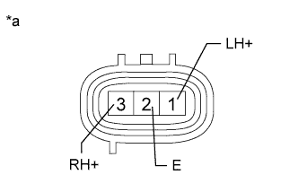
Text in Illustration *a Component without harness connected
(No. 2 Height Control Valve)
Measure the resistance according to the values in the table below.
Standard Resistance Tester Connection Condition Specified Condition 1 (LH+) - 2 (E) 15 to 25°C (59 to 77°F) 17.5 to 21.5 Ω 3 (RH+) - 2 (E) 15 to 25°C (59 to 77°F) 10 to 14 Ω -
Check the leveling solenoid valve.
-
Connect the positive (+) lead of the battery to terminal 3 (RH+) and the negative (-) lead to terminal 2 (E).
-
Check the operating sound of the No. 2. height control valve
OK It makes an operating sound (click).
-
-
Check the gate solenoid valve.
-
Connect the positive (+) lead of the battery to terminal 1 (LH+) and the negative (-) lead to terminal 2 (E).
-
Check the operating sound of the No. 2. height control valve.
OK It makes an operating sound (click).
-
NG
REPLACE NO. 2 HEIGHT CONTROL VALVE Click here
OK
-
-
INSPECT HEIGHT CONTROL COMPRESSOR (EXHAUST SOLENOID VALVE)
-
Turn the ignition switch off.
-
Remove the height control compressor Click here.
-
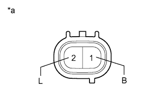
Text in Illustration *a Component without harness connected
(Exhaust Valve)
Measure the resistance according to the value(s) in the table below.
Standard Resistance Tester Connection Condition Specified Condition 2 (L) - 1 (B) 20°C (68°F) 10 to 14 Ω -
Connect the positive (+) lead of the battery to terminal 2 (L) and the negative (-) lead to terminal 1 (B) of the solenoid valve connector. Then check that the valve makes an operating sound.
OK Operation of solenoid (clicking sound) can be heard.
NG
REPLACE HEIGHT CONTROL COMPRESSOR ASSEMBLY Click here
OK
-
-
INSPECT HEIGHT CONTROL COMPRESSOR (COMPRESSOR MOTOR)
-
Remove the height control compressor Click here.
-
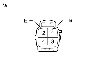
Text in Illustration *a Component without harness connected
(Height Control Compressor)
Apply 12 V battery voltage to the compressor motor and check the operation of the motor.
OK Measurement Condition Specified Condition 12 V battery positive (+) voltage → Terminal 1 (B)
12 V battery negative (-) voltage → Terminal 2 (E)
Motor operates Note
-
Do not allow the compressor motor to operate for approximately 90 seconds or more.
-
If the compressor is shorted, locked or has a similar type of malfunction, a large amount of current is flowing. Therefore, if the motor does not operate, immediately stop this inspection.
-
NG
REPLACE HEIGHT CONTROL COMPRESSOR ASSEMBLY Click here
OK
-
-
INSPECT SUSPENSION CONTROL RELAY (AIR SUS)
-
Turn the ignition switch off.
-
Remove the AIR SUS relay from the engine room relay block.
-
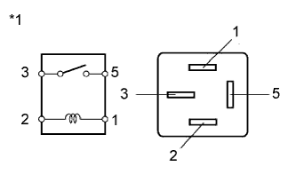
Text in Illustration *1 AIR SUS Relay Measure the resistance according to the value(s) in the table below.
Standard Resistance Tester Connection Condition Specified Condition 3 - 5 12 V battery voltage is not applied to terminal 1 and 2 10 kΩ or higher 12 V battery voltage is applied to terminal 1 and 2 Below 1 Ω
NG
REPLACE SUSPENSION CONTROL RELAY (AIR SUS)
OK 
REPLACE SUSPENSION CONTROL ECU Click here
-