AUTOMATIC TRANSMISSION SYSTEM (for 1KD-FTV), Diagnostic DTC:P2716

| DTC Code | DTC Name |
|---|---|
| P2716 | Pressure Control Solenoid "D" Electrical (Shift Solenoid Valve SLT) |
DESCRIPTION
Refer to DTC P2714 Click here.
| DTC Code | DTC Detection Condition | Trouble Area |
|---|---|---|
| P2716 | Open or short is detected in the shift solenoid valve SLT circuit for 1 sec. or more while driving (1-trip detection logic). |
|
MONITOR DESCRIPTION
When an open or short in the shift solenoid valve SLT circuit is detected, the TCM interprets this as a fault. The TCM will turn on the MIL and store the DTC.
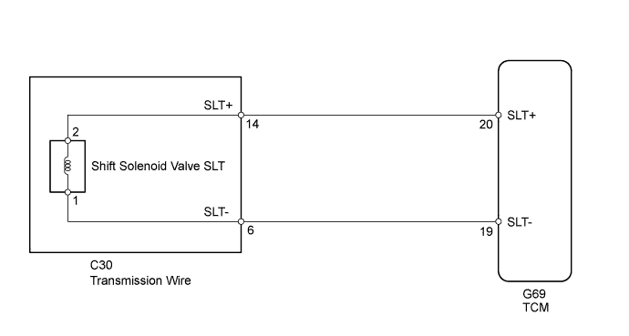
WIRING DIAGRAM
INSPECTION PROCEDURE
PROCEDURE
-
INSPECT TRANSMISSION WIRE (SHIFT SOLENOID VALVE SLT)
-
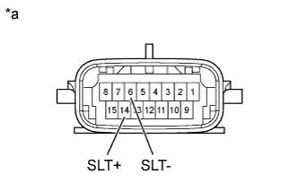
Text in Illustration *a Component without harness connected
(Transmission Wire)
Disconnect the C30 transmission wire connector.
-
Measure the resistance according to the value(s) in the table below.
Standard Resistance Tester Connection Condition Specified Condition 14 (SLT+) - 6 (SLT-) 20°C (68°F) 5.0 to 5.6 Ω 14 (SLT+) - Body ground 20°C (68°F) 10 kΩ or higher 6 (SLT-) - Body ground 20°C (68°F) 10 kΩ or higher
NG 
OK 
-
-
CHECK HARNESS AND CONNECTOR (TRANSMISSION WIRE - TCM)
-
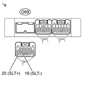
Text in Illustration *a Rear view of wire harness connector
(to TCM)
Disconnect the G69 TCM connector.
-
Measure the resistance according to the value(s) in the table below.
Standard Resistance Tester Connection Condition Specified Condition G69-20 (SLT+) - G69-19 (SLT-) 20°C (68°F) 5.0 to 5.6 Ω G69-20 (SLT+) - Body ground 20°C (68°F) 10 kΩ or higher G69-19 (SLT-) - Body ground 20°C (68°F) 10 kΩ or higher
NG 
REPAIR OR REPLACE HARNESS OR CONNECTOR
OK 
REPLACE TCM Click here
-
-
INSPECT SHIFT SOLENOID VALVE SLT
-
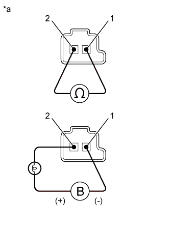
Text in Illustration *a Component without harness connected
(Shift Solenoid Valve SLT)
Remove shift solenoid valve SLT.
-
Measure the resistance according to the value(s) in the table below.
Standard Resistance Tester Connection Condition Specified Condition 1 - 2 20°C (68°F) 5.0 to 5.6 Ω -
Apply 12 V battery voltage to the shift solenoid valve and check that the valve moves and makes an operating noise.
OK Measurement Condition Specified Condition
-
Battery positive (+) with a 21 W bulb → Terminal 2
-
Battery negative (-) → Terminal 1
Valve moves and makes an operating noise -
NG
REPLACE SHIFT SOLENOID VALVE SLT Click here
OK
REPAIR OR REPLACE TRANSMISSION WIRE Click here
-