INSTRUMENT PANEL SAFETY PAD INSTALLATION

Tech Tips
-
Use the same procedure for RHD and LHD vehicles.
-
The procedure listed below is for LHD vehicles.
-
A bolt without a torque specification is shown in the standard bolt chart Click here.
-
INSTALL INSTRUMENT PANEL SAFETY PAD SUB-ASSEMBLY
-
for LHD:
-
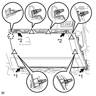
Attach the 2 guides to install the instrument panel safety pad.
-
Install the 2 brackets with the 4 bolts and 2 nuts.
-
Connect the connectors and attach the clamps and claws.
-
Install the 2 passenger airbag bolts <G>.
- Torque:
- 20 N*m { 204 kgf*cm, 15 ft.*lbf }
-
Install the 6 bolts <E> and nut <F>.
-
Install the front floor carpet.
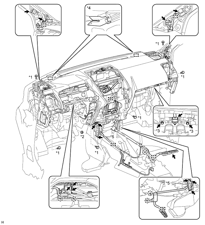
Text in Illustration *1 Bolt <E> *2 Nut <F> *3 Bolt <G> *4 Guide *5 Bracket - -
-
-
for RHD:
-
Attach the 2 guides to install the instrument panel safety pad.
-
Install the 2 brackets with the 4 bolts and 2 nuts.
-
Connect the connectors and attach the clamps and claws.
-
Install the 2 passenger airbag bolts <G>.
- Torque:
- 20 N*m { 204 kgf*cm, 15 ft.*lbf }
-
Install the 6 bolts <E> and nut <F>.
-
Install the front floor carpet.
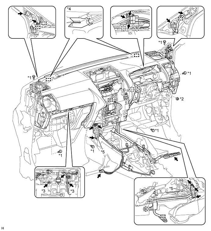
Text in Illustration *1 Bolt <E> *2 Nut <F> *3 Bolt <G> *4 Guide *5 Bracket - -
-
-
-
INSTALL FRONT NO. 3 SPEAKER ASSEMBLY
-
Attach the clip and claw to install the front No. 3 speaker.
-
Connect the connector.
-
-
INSTALL FRONT NO. 2 SPEAKER ASSEMBLY
-
Connect the connector.
-
Align the speaker with the positioning pins of the instrument panel and temporarily install the speaker.
-
Install the front No. 2 speaker with the 2 bolts.
Note
-
Do not touch the cone of the speaker.
-
When installing the speaker to the instrument panel, be careful that the wires do not get caught between parts.
-
-
-
INSTALL NO. 1 INSTRUMENT PANEL SPEAKER PANEL SUB-ASSEMBLY
-
Attach the 2 clips, claw and 2 guides to install the No. 1 instrument panel speaker panel.
-
-
INSTALL NO. 2 INSTRUMENT PANEL SPEAKER PANEL SUB-ASSEMBLY
Tech Tips
Use the same procedure described for the No. 1 instrument panel speaker panel.
-
INSTALL NO. 1 INSTRUMENT PANEL REGISTER ASSEMBLY
-
Attach the 4 clips to install the No. 1 instrument panel register.
-
-
INSTALL NO. 2 INSTRUMENT PANEL REGISTER ASSEMBLY
Tech Tips
Use the same procedure described for the No. 1 instrument panel register.
-
INSTALL FRONT NO. 4 SPEAKER ASSEMBLY
-
Connect the speaker connector.
-
Align the speaker with the positioning pins of the instrument panel and temporarily install the speaker.
-
Install the front No. 4 speaker with the 2 bolts.
Note
-
Do not touch the cone of the speaker.
-
When installing the speaker to the instrument panel, be careful that the wires do not get caught between parts.
-
-
-
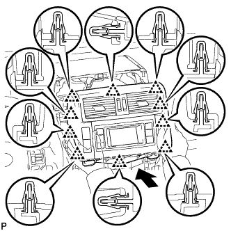
INSTALL UPPER INSTRUMENT CLUSTER FINISH PANEL
-
Attach the 8 clips and 2 guides to install the upper instrument cluster finish panel.
-
-
INSTALL RADIO RECEIVER ASSEMBLY (w/ Audio)
-
for Upper Side:
Install the radio receiver assembly Click here.
-
for Lower Side:
Install the radio receiver assembly Click here.
-
-
INSTALL LOWER CENTER INSTRUMENT CLUSTER FINISH PANEL SUB-ASSEMBLY (w/o Audio)
-
Attach the 3 clips and guide to install the lower center instrument cluster finish panel.
-
Install the 2 bolts <E>.
-
-
INSTALL ACCESSORY METER ASSEMBLY (w/ Display, w/o Navigation System)
-
Connect the connectors.
-
Insert the accessory meter and attach the 10 clips on its backside.
-
Install the accessory meter with the 2 bolts.
- Torque:
- 12 N*m { 122 kgf*cm, 9 ft.*lbf }
-
-
INSTALL DISPLAY AND NAVIGATION MODULE DISPLAY (w/ Display, w/ Navigation System)
-
Connect the connectors.
-
Insert the display and navigation module display and attach the 8 clips on the backside of the display and navigation module display.
Note
When inserting the display, do not press the knobs on it.
-
Install the display and navigation module display with the 4 bolts.
- Torque:
- 12.5 N*m { 127 kgf*cm, 9 ft.*lbf }
-
-
INSTALL RADIO TUNER OPENING COVER (w/o Audio)
-
Install the radio tuner opening cover with the 4 bolts.
-
-
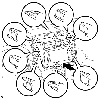
INSTALL CENTER INSTRUMENT CLUSTER FINISH PANEL ASSEMBLY (w/o Display)
-
Attach the 10 clips to install the center instrument cluster finish panel.
-
-
REMOVE MULTI-MEDIA INTERFACE ECU
-
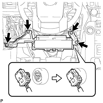
Install the multi-media interface ECU with the 2 nuts.
- Torque:
- 5.5 N*m { 56 kgf*cm, 49 in.*lbf }
-
Connect the 3 connectors.
-
-
REMOVE 4 WHEEL DRIVE CONTROL ECU
-
Install the four wheel drive control ECU with the bolt.
- Torque:
- 13 N*m { 127 kgf*cm, 9 ft.*lbf }
-
Connect the 2 connectors.
-
-
INSTALL DRIVING SUPPORT SWITCH CONTROL ECU
-
Install the driving support switch control ECU with the bolt.
- Torque:
- 13 N*m { 127 kgf*cm, 9 ft.*lbf }
-
Connect the connector.
-
-
INSTALL GLOVE COMPARTMENT DOOR ASSEMBLY
Text in Illustration *1 Bolt *2 Screw
-
Connect each connector.
-
Attach the 5 clips and claw to install the glove compartment door.
-
Install the 2 bolts <C> and 2 screws <A> or <B>.
-
-
INSTALL INSTRUMENT PANEL ORNAMENT
-
Attach the 5 clips to install the instrument panel ornament.
-
-
INSTALL INSTRUMENT SIDE PANEL RH
-
Connect the connector.
-
Attach the 5 clips, claw and 3 guides to install the instrument side panel.
-
-
INSTALL COMBINATION METER ASSEMBLY
-
Connect the connector.
-
Install the combination meter with the 4 screws.
-
-
INSTALL INSTRUMENT CLUSTER FINISH PANEL SUB-ASSEMBLY
-
Attach the 4 claws, 2 clips and 2 guides to install the instrument cluster finish panel.
-
-
INSTALL LOWER NO. 1 INSTRUMENT PANEL AIRBAG ASSEMBLY
-
Connect the connector.
Note
When handling the airbag connector, take care not to damage the airbag wire harness.
-
Install the airbag assembly with the 4 bolts.
- Torque:
- 10 N*m { 102 kgf*cm, 7 ft.*lbf }
-
-
INSTALL LOWER INSTRUMENT PANEL FINISH PANEL SUB-ASSEMBLY
-
Connect each connector and each cable.
-
w/o Knee Airbag:
-
Attach the 7 clips to install the lower instrument panel finish panel.
-
-
w/ Knee Airbag:
-
Attach the 14 clips to install the lower instrument panel finish panel.
-
-
Install the 2 bolts <C>.
-
Attach the 2 claws to close the cover.
-
-
INSTALL LOWER INSTRUMENT PANEL FINISH PANEL ASSEMBLY
-
Connect each connector.
-
Attach the 4 clips to install the instrument panel finish panel.
-
-
INSTALL INSTRUMENT PANEL FINISH PLATE GARNISH (for RHD)
-
Connect each connector.
-
Attach the 4 clips to install the instrument panel finish plate garnish.
-
-
INSTALL INSTRUMENT CLUSTER FINISH PANEL ORNAMENT (for LHD)
-
Attach the 3 clips to install the instrument cluster finish panel ornament.
-
-
INSTALL INSTRUMENT SIDE PANEL LH
-
Attach the 5 clips, claw and 3 guides to install the instrument side panel.
-
-
INSTALL FRONT PILLAR GARNISH LH
-
Attach the 3 guides to install the front pillar garnish.
-
-
INSTALL FRONT PILLAR GARNISH RH
Tech Tips
Use the same procedure described for the LH side.
-
INSTALL NO. 1 ASSIST GRIP
Tech Tips
Use the same procedure for the other No. 1 assist grip.
-
Attach the 2 claws to install the No. 1 assist grip.
-
Install the 2 bolts.
-
-
INSTALL NO. 1 FRONT ASSIST GRIP PLUG LH
Tech Tips
Use the same procedure for the other front No. 1 assist grip plug.
-
Attach the 2 claws to install the front No. 1 assist grip plug.
-
-
INSTALL NO. 1 FRONT ASSIST GRIP PLUG RH
Tech Tips
Use the same procedure described for the LH side.
-
INSTALL FRONT DOOR OPENING TRIM WEATHERSTRIP LH
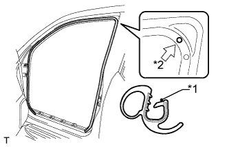
Text in Illustration *1 Paint Mark *2 Mark Position
-
Align the paint mark on the front door opening trim weatherstrip with the mark position on the vehicle and install the front door opening trim weatherstrip as shown in the illustration.
-
-
INSTALL FRONT DOOR OPENING TRIM WEATHERSTRIP RH
Tech Tips
Use the same procedure described for the LH side.
-
INSTALL COWL SIDE TRIM BOARD LH
-
Attach the clip and claw to install the cowl side trim board.
-
Install the clip.
-
-
INSTALL COWL SIDE TRIM BOARD RH
Tech Tips
Use the same procedure described for the LH side.
-
INSTALL DOOR SCUFF PLATE ASSEMBLY LH
-
Attach the 4 clips, 10 claws and 2 guides to install the door scuff plate.
-
-
INSTALL DOOR SCUFF PLATE ASSEMBLY RH
Tech Tips
Use the same procedure described for the LH side.
-
INSTALL REAR CONSOLE BOX ASSEMBLY
-
for Automatic Transmission:
Install the rear console box assembly Click here.
-
for Manual Transmission:
Install the rear console box assembly Click here.
-
w/ Refrigerated Cool Box:
Install the rear console box assembly Click here.
-
for Bench Seat Type:
Install the rear console box assembly Click here.
-
-
INSTALL FRONT FLOOR FOOTREST
-
for LHD:
Install the front floor footrest Click here.
-
for RHD:
Install the front floor footrest Click here.
-
-
INSTALL FRONT SEAT ASSEMBLY LH
-
for Manual Seat:
Install the front seat assembly Click here.
-
for Power Seat:
Install the front seat assembly Click here.
-
-
INSTALL FRONT SEAT ASSEMBLY RH
-
for Manual Seat:
Tech Tips
Use the same procedure described for the LH side.
-
for Power Seat:
Tech Tips
Use the same procedure described for the LH side.
-
for Walk in Seat Type:
Install the front seat assembly Click here.
-
-
INSTALL HEADLIGHT DIMMER SWITCH ASSEMBLY
-
Install the headlight dimmer switch assembly Click here.
-
-
CONNECT CABLE TO NEGATIVE BATTERY TERMINAL
Note
-
Reset the AUTO TILT AWAY function setting to the previous condition by changing the customize parameter Click here.
-
When disconnecting the cable, some systems need to be initialized after the cable is reconnected Click here.
-
-
CHECK SRS WARNING LIGHT
-
Check the SRS warning light Click here.
-