FRONT AIR CONDITIONING UNIT INSTALLATION

Tech Tips
-
Use the same procedure for RHD and LHD vehicles.
-
The procedure listed below is for LHD vehicles.
-
A bolt without a torque specification is shown in the standard bolt chart Click here.
-
INSTALL INSTRUMENT PANEL REINFORCEMENT ASSEMBLY
-
Attach the 2 claws to install the instrument panel reinforcement assembly.
-
Install the 5 bolts.
- Torque:
- 9.8 N*m { 100 kgf*cm, 87 in.*lbf }
-
-
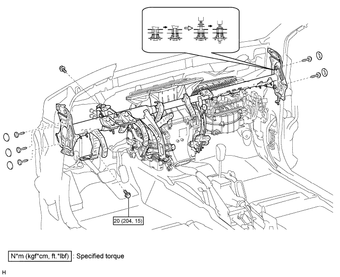
INSTALL INSTRUMENT PANEL REINFORCEMENT ASSEMBLY WITH AIR CONDITIONING UNIT ASSEMBLY
-
Install the instrument panel reinforcement assembly with air conditioning unit assembly.
-
Install the bolts and nuts and instrument panel reinforcement assembly with air conditioning unit assembly.
-
Using a 12 mm hexagon wrench, tighten the 2 collars.
- Torque:
- 27 N*m { 275 kgf*cm, 20 ft.*lbf }
-
Using a T40 "TORX" socket, install the 5 "TORX" bolts.
- Torque:
- 27 N*m { 275 kgf*cm, 20 ft.*lbf }
-
Install the 5 caps.
-
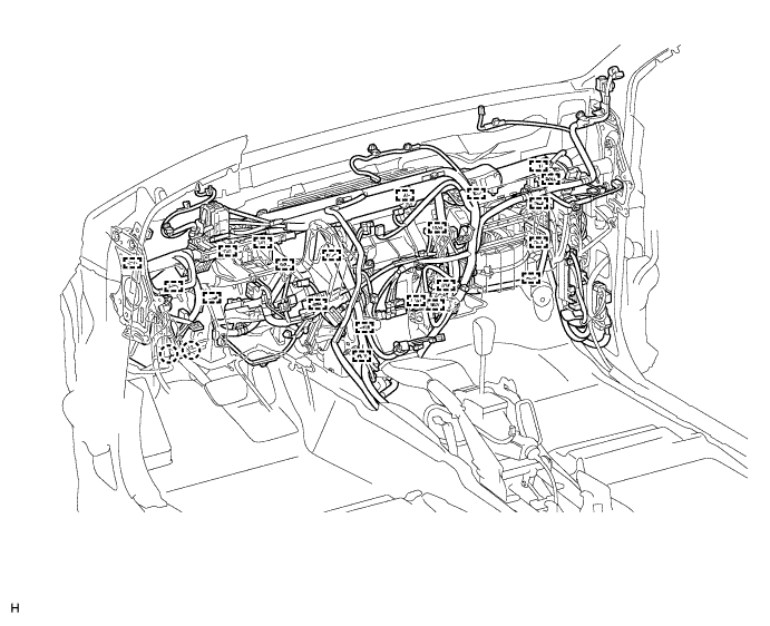
Attach the clamps and connectors to the wire harness.
-
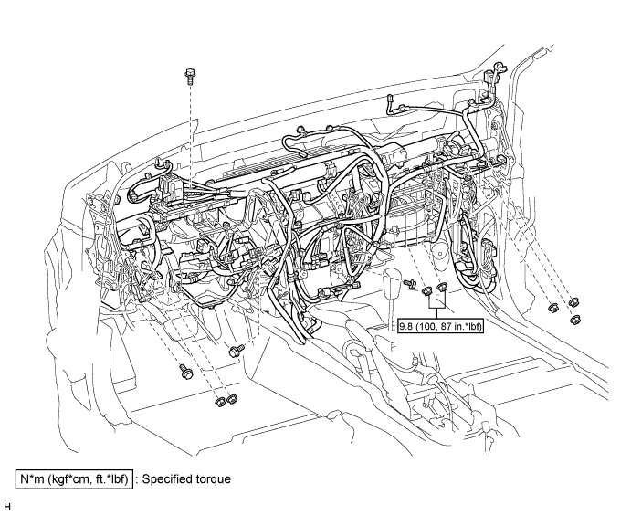
Install the bolts and nuts.
-
-
-
INSTALL NO. 1 AIR DUCT SUB-ASSEMBLY
-
Attach the 3 claws to install the No. 1 air duct sub-assembly.
-
-
INSTALL NO. 2 AIR DUCT SUB-ASSEMBLY
-
Attach the 2 claws to install the No. 2 air duct sub-assembly.
-
Install the screw.
-
-
INSTALL NO. 1 INSTRUMENT PANEL BRACE MOUNTING BRACKET LH
-
Install the No. 1 instrument panel brace mounting bracket LH with the 2 nuts and bolt.
-
-
INSTALL NO. 1 INSTRUMENT PANEL BRACE MOUNTING BRACKET RH
-
Install the No. 1 instrument panel brace mounting bracket RH with the 2 nuts and bolt.
-
-
INSTALL NO. 1 CONSOLE BOX DUCT
-
Install the No. 1 console box duct with the clip.
-
-
INSTALL REAR NO. 3 AIR DUCT
-
Attach the 6 claws and 3 clamps to install the rear No. 3 air duct.
-
-
INSTALL REAR NO. 1 AIR DUCT
-
Attach the 6 claws and 3 clamps to install the rear No. 1 air duct.
-
-
INSTALL FRONT CARPET ASSEMBLY
-
Install the front floor carpet assembly.
-
-
INSTALL FRONT SEAT ASSEMBLY LH
-
for Manual Seat:
Install the front seat assembly LH Click here.
-
for Power Seat:
Install the front seat assembly LH Click here.
-
for Walk in Seat Type:
Install the front seat assembly LH Click here.
-
for Bench Seat Type:
Install the front seat assembly LH Click here.
-
-
INSTALL FRONT SEAT ASSEMBLY RH
-
for Manual Seat:
Install the front seat assembly RH Click here.
-
for Power Seat:
Install the front seat assembly RH Click here.
-
for Walk in Seat Type:
Install the front seat assembly RH Click here.
-
for Bench Seat Type:
Install the front seat assembly RH Click here.
-
-
INSTALL STEERING COLUMN ASSEMBLY
-
for Manual Tilt and Manual Telescopic Steering Column:
Install the steering column assembly Click here.
-
for Power Tilt and Power Telescopic Steering Column:
Install the steering column assembly Click here.
-
-
INSTALL INSTRUMENT PANEL SUB-ASSEMBLY
-
Install the instrument panel sub-assembly Click here.
-
-
INSTALL WINDSHIELD WIPER MOTOR ASSEMBLY
-
Install the windshield wiper motor assembly Click here.
-
-
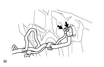
CONNECT HEATER WATER INLET HOSE AND OUTLET HOSE
-
Connect the 2 heater water hose.
-
Using pliers, grip the claws of the clips and slide the 2 clips.
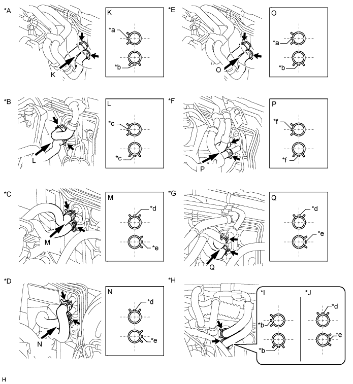
Text in Illustration *A for 1GR-FE, for Single Air Conditioning System *B for 1KD-FTV, for Single Air Conditioning System *C for 5L-E, for Single Air Conditioning System *D for 2TR-FE, for Single Air Conditioning System *E for 1GR-FE, for Dual Air Conditioning System *F for 1KD-FTV, Dual Air Conditioning System *G for 5L-E, Dual Air Conditioning System *H for 2TR-FE, Dual Air Conditioning System *I for Dual Air Conditioning System, for LHD *J for Dual Air Conditioning System, for RHD *a Green Marking *b Blue Marking *c Orange Marking *d Yellow Marking *e White Marking *f Pink Marking
-
-
CONNECT AIR CONDITIONING TUBE AND ACCESSORY ASSEMBLY (for Bolt Joint Type)
-
Sufficiently apply compressor oil to 2 new O-rings and the fitting surface of the air conditioning tube and accessory assembly.
Compressor oil ND-OIL 8 or equivalent -
Install the 2 O-rings to the air conditioning tube and accessory assembly.
-
Connect the air conditioning tube and accessory assembly.
-
Install the 2 bolts.
- Torque:
- 9.8 N*m { 100 kgf*cm, 87 in.*lbf }
-
-
CONNECT AIR CONDITIONING TUBE AND ACCESSORY ASSEMBLY (for Quick Joint Type)
-
Install the grommet.
-
Install the 2 O-rings to the air conditioning tube and accessory assembly.
-
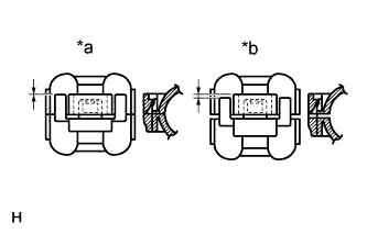
Text in Illustration *a CORRECT *b INCORRECT Connect the air conditioning tube and accessory assembly with the piping clamp.
Compressor oil ND-OIL 8 or equivalent Note
After the connection, check that the claw of the piping clamp is attached.
-
-
CONNECT CABLE TO NEGATIVE BATTERY TERMINAL
Note
When disconnecting the cable, some systems need to be initialized after the cable is reconnected Click here.
-
CHARGE REFRIGERANT
- SST
- 09985-20010 ( 09985-02130, 09985-02150, 09985-02090, 09985-02110, 09985-02010, 09985-02050, 09985-02060, 09985-02070 )
-
Perform vacuum purging using a vacuum pump.
-
Charge refrigerant HFC-134a (R134a).
Standard Model Code Air Conditioning Type Cool Box Refrigerant Charging Amount Except the model codes below w/o Rear Cooler w/ Cool Box 600 +/-30 g (21.2 +/-1.1 oz.) w/o Cool Box 550 +/-30 g (19.3 +/-1.1 oz.) w/ Rear Cooler w/ Cool Box 800 +/-30 g (28.2 +/-1.1 oz.) w/o Cool Box 770 +/-30 g (27.2 +/-1.1 oz.) w/ Rear Cooler
for Cold Area Specification Vehicles
w/o Cool Box 720 +/-30 g (25.3 +/-1.1 oz.) TRJ150L-GKMEKV
TRJ150L-GKPEKV
TRJ155L-GJPEKV
GRJ150L-GKFEKV
GRJ150L-GKAEKV
KDJ150L-GKFEYV
KDJ150L-GKAEYV
w/o Rear Cooler w/ Cool Box 600 +/-30 g (21.2 +/-1.1 oz.) w/o Cool Box 550 +/-30 g (19.3 +/-1.1 oz.) or 600 +/-30 g (21.2 +/-1.1 oz.) *1 w/ Rear Cooler w/ Cool Box 800 +/-30 g (28.2 +/-1.1 oz.) w/o Cool Box 770 +/-30 g (27.2 +/-1.1 oz.) *1: For vehicles with the 2TR-FE engine which have neither the rear cooler nor cool box, the refrigerant charging amount changes based on region.
Note
-
Do not operate the cooler compressor before charging refrigerant as the cooler compressor will not work properly without any refrigerant, and will overheat.
-
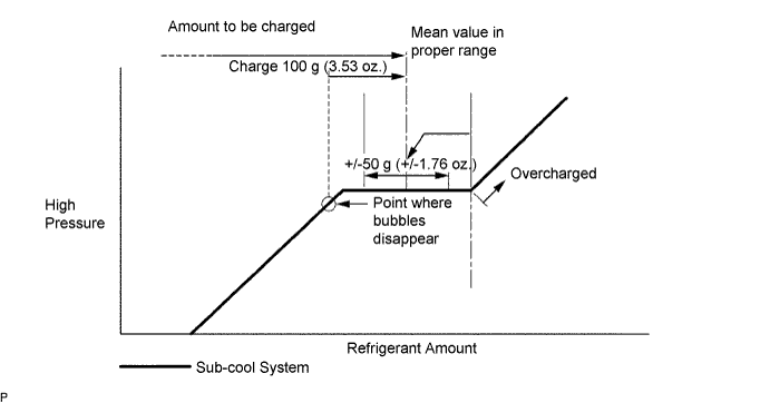
Approximately 100 g (3.53 oz.) of refrigerant may need to be charged after bubbles disappear. The refrigerant amount should be checked by measuring its quantity, and not with the sight glass.
-
-
ADD ENGINE COOLANT
-
for 1GR-FE:
Add engine coolant Click here.
-
for 2TR-FE:
Add engine coolant Click here.
-
for 1KD-FTV:
Add engine coolant Click here.
-
for 5L-E:
Add engine coolant Click here.
-
-
WARM UP ENGINE
-
Warm up the engine at less than 1850 rpm for 2 minutes or more after charging the refrigerant.
Note
Be sure to warm up the compressor when turning the A/C switch is on after removing and installing the cooler refrigerant lines (including the compressor), to prevent damage to the compressor.
-
-
INSPECT FOR COOLANT LEAK
-
for 1GR-FE:
Inspect for coolant leak Click here.
-
for 2TR-FE:
Inspect for coolant leak Click here.
-
for 1KD-FTV:
Inspect for coolant leak Click here.
-
for 5L-E:
Inspect for coolant leak Click here.
-
-
CHECK FOR REFRIGERANT GAS LEAK
-
After recharging the refrigerant gas, check for refrigerant gas leakage using a halogen leak detector.
-
Perform the operation under these conditions:
-
Stop the engine.
-
Secure good ventilation (the halogen leak detector may react to volatile gases other than refrigerant, such as evaporated gasoline or exhaust gas).
-
Repeat the test 2 or 3 times.
-
Make sure that some refrigerant remains in the refrigeration system. When compressor is off: approximately 392 to 588 kPa (4.0 to 6.0 kgf/cm2, 57 to 85 psi).
-
-
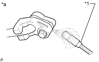
Text in Illustration *1 Halogen Leak Detector *a Check for Leakage Using a halogen leak detector, check the refrigerant line for leakage.
-
If a gas leak is not detected on the drain hose, remove the blower motor control (blower resistor) from the cooling unit. Insert the halogen leak detector sensor into the unit and perform the test.
-
Disconnect the connector and wait for approximately 20 minutes. Bring the halogen leak detector close to the pressure switch and perform the test.
-
-
CHECK SRS WARNING LIGHT
-
Check the SRS warning light Click here.
-