REMOTE ENGINE STARTER SYSTEM, Diagnostic DTC:B126A

| DTC Code | DTC Name |
|---|---|
| B126A | Remote Engine Starter ECU Communication Stop |
DESCRIPTION
This DTC is stored when BERKES communication between the remote engine starter ECU and main body ECU (multiplex network body ECU) stops for 10 seconds or more.
| DTC No. | DTC Detection Condition | Trouble Area |
|---|---|---|
| B126A | No communication between remote engine starter ECU and main body ECU (multiplex network body ECU) for 10 seconds or more. |
|
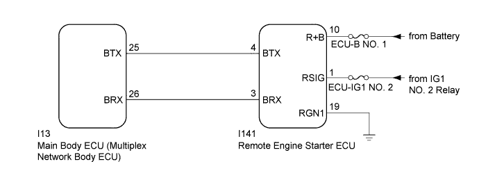
WIRING DIAGRAM
INSPECTION PROCEDURE
Note
-
Inspect the fuses for circuits related to this system before performing the following inspection procedure.
-
Before replacing the remote engine starter ECU, refer to Registration Click here.
PROCEDURE
-
CHECK HARNESS AND CONNECTOR (REMOTE ENGINE STARTER ECU - BATTERY AND BODY GROUND)
-
Disconnect the I141 remote engine starter ECU connector.
-
Measure the voltage and resistance according to the value(s) in the table below.
Standard Voltage Tester Connection Condition Specified Condition I141-10 (R+B) - Body ground Always 11 to 14 V I141-1 (RSIG) - Body ground Engine switch on (IG) 11 to 14 V I141-1 (RSIG) - Body ground Engine switch off Below 1 V Standard Resistance Tester Connection Condition Specified Condition I141-19 (RGN1) - Body ground Always Below 1 Ω
NG 
REPAIR OR REPLACE HARNESS OR CONNECTOR
OK 
-
-
CHECK HARNESS AND CONNECTOR (MAIN BODY ECU (MULTIPLEX NETWORK BODY ECU) - REMOTE ENGINE STARTER ECU)
-
Disconnect the I13 main body ECU (multiplex network body ECU) connector.
-
Measure the resistance according to the value(s) in the table below.
Standard Resistance Tester Connection Condition Specified Condition I13-25 (BTX) - I141-4 (BTX) Always Below 1 Ω I13-26 (BRX) - I141-3 (BRX) Always Below 1 Ω I13-25 (BTX) - Body ground Always 10 kΩ or higher I13-26 (BRX) - Body ground Always 10 kΩ or higher
NG
REPAIR OR REPLACE HARNESS OR CONNECTOR
OK
-
-
REPLACE REMOTE ENGINE STARTER ECU
-
Temporarily replace the remote engine starter ECU with a new one Click here.
NEXT
-
-
REGISTER REMOTE ENGINE STARTER ID
-
Register the remote engine starter ID Click here.
NEXT
-
-
CHECK DTC OUTPUT
-
Clear the DTC Click here.
-
Perform the remote engine start operation.
-
Check for DTCs.
OK DTC B126A is not output.
NG
REPLACE MAIN BODY ECU (MULTIPLEX NETWORK BODY ECU) Click here
OK 
END (REMOTE ENGINE STARTER ECU WAS DEFECTIVE)
-