ТОПЛИВНАЯ ФОРСУНКА УСТАНОВКА
-
INSTALL FUEL INJECTOR ASSEMBLY
-
Attach the 3 clamps to install the No. 6 wire harness to the delivery pipe RH.
-
Attach the 3 clamps to install the No. 7 wire harness to the delivery pipe LH.
-
Apply gasoline or spindle oil to a new O-ring and install it to the injector.
Note
Make sure that there is no damage or foreign material in the groove of the injector when installing the O-ring.
-
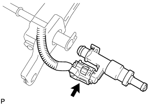
Connect the injector connector.
-
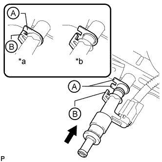
Text in Illustration *a CORRECT *b INCORRECT Install the injector to the delivery pipe as shown in the illustration.
Note
-
Make sure that there are no scratches or foreign matter in or around the insertion hole of the delivery pipe.
-
When inserting the injector, be careful not to damage the O-ring.
-
Attach the part of the injector labeled B between the parts of the delivery pipe labeled A.
-
-
Check that each injector is installed to the delivery pipe facing the direction shown in the illustration.
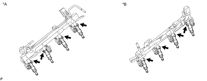
Text in Illustration *A Fuel Delivery Pipe RH *B Fuel Delivery Pipe LH
-
-
INSTALL FUEL DELIVERY PIPE SUB-ASSEMBLY LH
-
Install the 2 delivery pipe spacers and 4 insulators to the cylinder head LH.
-
Install the delivery pipe (with injectors) to the cylinder head LH.
-
Install the 2 bolts.
- Torque:
- 21 N*m { 214 kgf*cm, 15 ft.*lbf }
Note
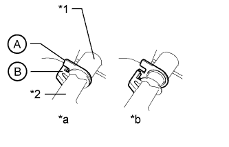
Make sure that the part of the injector labeled B is between the parts of the delivery pipe labeled A.
Text in Illustration *1 Delivery Pipe *2 Injector *a CORRECT *b INCORRECT -
Connect the No. 7 wire harness connector.
-
-
INSTALL FUEL DELIVERY PIPE SUB-ASSEMBLY RH
-
Install the 2 delivery pipe spacers and 4 insulators to the cylinder head RH.
-
Install the delivery pipe (with injectors) to the cylinder head RH.
-
Install the 2 bolts.
- Torque:
- 21 N*m { 214 kgf*cm, 15 ft.*lbf }
Note
Make sure that the part of the injector labeled B is between the parts of the delivery pipe labeled A.
Text in Illustration *1 Delivery Pipe *2 Injector *a CORRECT *b INCORRECT -
Connect the No. 6 wire harness connector.
-
Connect the ventilation hose.
-
-
CONNECT NO. 1 FUEL HOSE
-
Connect the No. 1 fuel hose to the fuel delivery pipe LH Click here.
-
-
CONNECT NO. 1 FUEL TUBE
-
LH Side:
Connect the No. 1 fuel tube to the delivery pipe LH Click here.
-
Connect the No. 1 fuel tube to the delivery pipe RH (for metallic type) Click here.
-
-
CONNECT NO. 2 FUEL TUBE
-
Connect the No. 2 fuel tube to the fuel pressure regulator Click here.
-
-
INSTALL NO. 1 ENGINE COVER SUB-ASSEMBLY
-
INSTALL NO. 3 ENGINE COVER
-
INSTALL AIR CLEANER HOSE ASSEMBLY
-
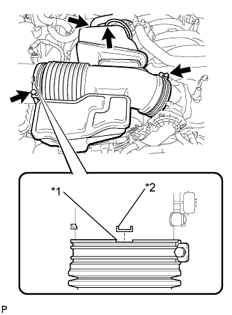
Обозначения на рисунке *1 Канавка *2 Выступы Установите шланг воздушного фильтра таким образом, чтобы выступ крышки воздушного фильтра совпадал с канавкой шланга, как показано на рисунке.
-
Затяните 2 зажима.
- Torque:
- 2,5 Н*м { 25 кгс*см, 22 фунт-сила-дюйма }
-
Подсоедините вакуумный шланг.
-
Подсоедините шланг вентиляции картера № 2.
-
-
INSTALL V-BANK COVER SUB-ASSEMBLY
-
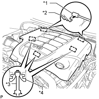
Обозначения на рисунке *1 Кронштейн *2 Крепежный крюк *3 Штифт *4 Уплотнительная шайба Совместите 2 крюка крышки V-образного двигателя с кронштейном. Затем совместите 3 уплотнительных шайбы декоративной крышки V-образного двигателя с 3 штифтами и нажмите на декоративную крышку V-образного двигателя, чтобы закрепить штифты.
-
-
CONNECT CABLE TO NEGATIVE BATTERY TERMINAL
Note
When disconnecting the cable, some systems need to be initialized after the cable is reconnected Click here.
-
INSPECT FOR FUEL LEAK
-
Connect the intelligent tester to the DLC3.
-
Turn the engine switch on (IG) and intelligent tester main switch on.
Note
Do not start the engine.
-
Enter the following menus: Powertrain / Engine and ECT / Active Test / Control the Fuel Pump / Speed.
-
Check that there are no fuel leaks after doing maintenance anywhere on the fuel system.
-