HAZARD WARNING SWITCH INSTALLATION

Tech Tips
-
Use the same procedures for the RHD and LHD.
-
The procedures listed below are the LHD side.
-
INSTALL HAZARD WARNING SIGNAL SWITCH ASSEMBLY
-
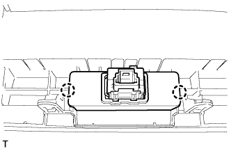
Attach the 2 claws to install the hazard warning switch.
-
-
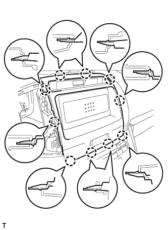
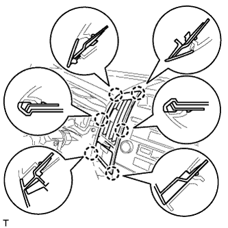
INSTALL CENTER NO. 1 INSTRUMENT CLUSTER FINISH PANEL (w/o Radio Receiver)
-
Connect the connector.
-
Attach the 10 claws to install the No. 1 center instrument cluster finish panel.
-
-
INSTALL RADIO RECEIVER ASSEMBLY (w/ Radio Receiver)
-
Connect the connectors.
-
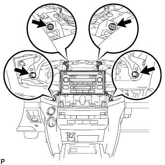
Install the radio receiver with the 2 screws and 2 bolts.
- Torque:
- Bolt
- 12 N*m { 122 kgf*cm, 9 ft.*lbf }
-
-
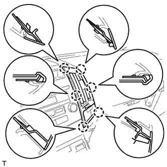
INSTALL NO. 4 INSTRUMENT PANEL REGISTER ASSEMBLY
-
Connect the connector.
-
Attach the 6 claws to install the No. 4 instrument panel register.
-
-
INSTALL NO. 3 INSTRUMENT PANEL REGISTER ASSEMBLY
-
Connect the connector.
-
Attach the 6 claws to install the No. 3 instrument panel register.
-
-
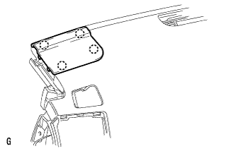
INSTALL NO. 1 SPEAKER OPENING COVER ASSEMBLY
-
Attach the 4 claws to install the panel.
-
-
CONNECT CABLE TO NEGATIVE BATTERY TERMINAL
Note
When disconnecting the cable, some systems need to be initialized after the cable is reconnected Click here.