- Click here
INSTALL BACK DOOR DAMPER ASSEMBLY (w/ Power Back Door)
-
When reusing the back door damper assembly:
-
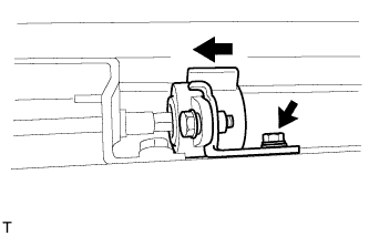
Install the back door damper assembly with the bolt.
7.5 N*m 76 kgf*cm 66 in.*lbf
-
-

When installing a new back door damper assembly:
-
With closing the tail gate, install a new back door damper assembly with the bolt.
7.5 N*m 76 kgf*cm 66 in.*lbf
-
-
- Click here
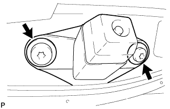
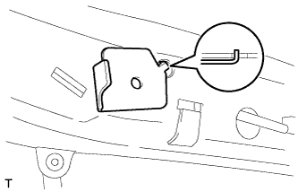
INSTALL TAIL GATE STAY SUB-ASSEMBLY LH
-
Clean the threaded surface on the vehicle body with a non-residue solvent.
-
Apply adhesive to the threads of the screws.
Adhesive Toyota Genuine Adhesive 1324, Three Bond 1324 or equivalent -
Using a T40 "TORX" wrench, install the 2 screws and tail gate stay.
-
- Click here
INSTALL TAIL GATE STAY SUB-ASSEMBLY RH
Tip:Use the same procedure described for the LH side.
- Click here
INSTALL LOWER TAIL GATE LOCK ASSEMBLY LH
-
w/o Power Back Door:
-
Using a T30 "TORX" wrench, install the 3 screws and lower tail gate lock assembly LH.
5.0 N*m 51 kgf*cm 44 in.*lbf
-
-
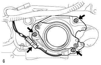
w/ Power Back Door:
-
Using a T30 "TORX" wrench, install the 4 screws and lower tail gate lock assembly LH.
5.0 N*m 51 kgf*cm 44 in.*lbf -
Connect the connector.
-
-
- Click here
INSTALL BACK DOOR REMOTE CONTROL ASSEMBLY
-
w/o Power Back Door:
-
Connect the left side cable.
-
Using a T30 "TORX" wrench, install the 2 screws and back door remote control assembly.
5.0 N*m 51 kgf*cm 44 in.*lbf
-
-
w/ Power Back Door:
-
Connect the connector.
-
Using a T30 "TORX" wrench, install the 2 screws and back door remote control assembly.
5.0 N*m 51 kgf*cm 44 in.*lbf
-
-
- Click here
INSTALL LOWER TAIL GATE LOCK ASSEMBLY RH
-
w/o Power Back Door:
-
Connect the cable to the lower tail gate lock assembly RH.
-
Using a T30 "TORX" wrench, install the 3 screws and lower tail gate lock assembly RH.
5.0 N*m 51 kgf*cm 44 in.*lbf
-
-
w/ Power Back Door:
-
Using a T30 "TORX" wrench, install the 4 screws and lower tail gate lock assembly RH.
5.0 N*m 51 kgf*cm 44 in.*lbf -
Connect the connector.
-
-
- Click here
INSTALL BACK DOOR INSIDE HANDLE ASSEMBLY
-
Install the back door handle grommet.
-
Install the screw and back door inside handle assembly.
5.0 N*m 51 kgf*cm 44 in.*lbf
-
- Click here
INSTALL BACK DOOR TORSION BAR GUIDE
-
Attach the 2 claws to install the back door torsion bar guide.
-
- Click here
INSTALL LOWER BACK DOOR TORSION BAR ASSEMBLY
-
Install the 4 bolts and lower back door torsion bar assembly.
7.5 N*m 76 kgf*cm 66 in.*lbf
-
- Click here
INSTALL SPARE TIRE
- Click here
INSTALL REAR BUMPER ASSEMBLY
-
for Standard:
-
Install the rear bumper assembly (Click here).
-
-
w/ Towing Hitch:
-
Install the rear bumper assembly (Click here).
-
-
w/ Pintle Hook:
-
Install the rear bumper assembly (Click here).
-
-
- Click here
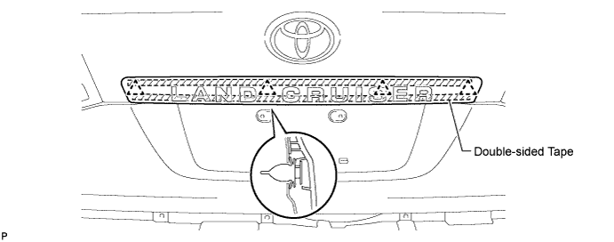
INSTALL REAR LICENSE LIGHT COVER (w/ Tire Carrier)
-
Clean the vehicle body surface.
-
Using a heat light, heat the vehicle body surface.
-
Remove the double-sided tape from the vehicle body.
-
Wipe off any tape adhesive residue with cleaner.
-
-
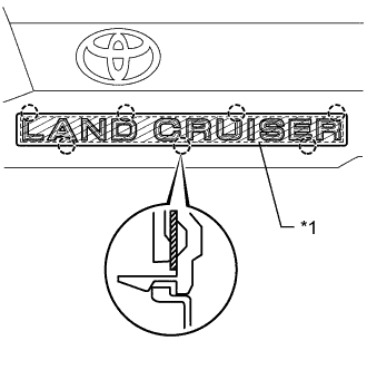
Install a new rear license light cover.
Table 1. Text in Illustration *1 Double-sided Tape
-
Using a heat light, heat the vehicle body and a new rear license light cover.
-
Remove the peeling paper from the face of the emblem.
Tip:After removing the peeling paper, keep the exposed adhesive free from foreign matter.
-
Attach the 7 claws to install the rear license light cover.
Tip:Press the rear license light cover firmly to install it.
-
-
- Click here
INSTALL LICENSE PLATE LIGHT ASSEMBLY (w/ Tire Carrier)
-
Install the 2 license plate lights with the 2 screws.
-
- Click here
INSTALL NO. 2 BACK DOOR OUTSIDE GARNISH SUB-ASSEMBLY (w/ Tire Carrier)
-
Pass the wire harness of the license plate light through the tail gate, and install the wire harness.
-
Attach the 7 clips to install the No. 2 back door garnish.
-
Install the 2 nuts and connect the connector.
-
- Click here
INSTALL BACK DOOR TRIM PANEL ASSEMBLY
-
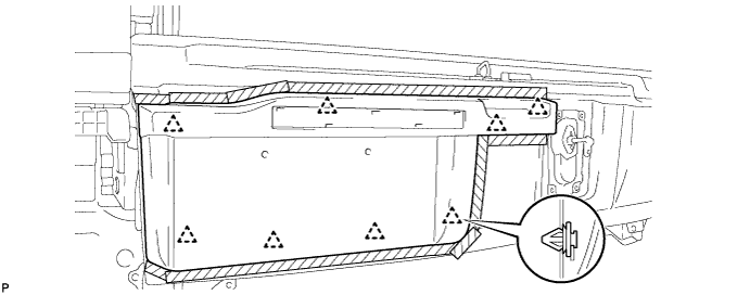
Attach the 16 clips to install the back door trim panel assembly.
-
Install the 4 bolts.
-
- Click here
INSTALL BACK DOOR TRIM COVER RH
-

Install the back door trim cover RH as shown in the illustration.
-
- Click here
INSTALL BACK DOOR TRIM COVER LH
-
Install the back door trim cover LH as shown in the illustration.
-
-
Click here
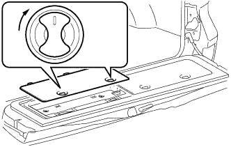
INSTALL REAR FLOOR MAT REAR SUPPORT PLATE
-
Attach the 6 clips to install the support plate.
-
- Click here
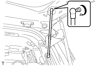
INSTALL BACK DOOR STAY ASSEMBLY LH
-
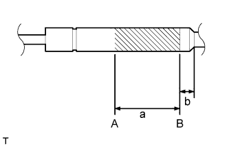
Horizontally fix the stay in a vise with the piston-rod pulled out.
-
Using a metal saw, gradually cut any area between A and B to release the gas.
Standard Measurement Area Specified Condition a 150 mm (5.91 in.) b 20 mm (0.787 in.) CAUTION:As metal debris may be blown outward by the gas, you must:
-
Wear protective glasses.
-
Cover the area being cut.
Note:The gas inside the hood support is colorless, odorless and harmless. As there is a possibility that metal debris could scatter, cover the back door stay with a piece of cloth or other material.
-
-
- Click here
INSTALL BACK DOOR STAY ASSEMBLY RH
Tip:Use the same procedure described for the LH side.
-
Click here
INSTALL REAR WASHER NOZZLE (w/ Rear Wiper)
-
Attach the 2 claws to install the rear washer nozzle.
-
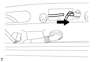
Connect the washer hose.
-
- Click here
INSTALL REAR SPOILER SUB-ASSEMBLY (w/ Rear Spoiler)
-
Attach the 3 clips to install the rear spoiler sub-assembly.
-
w/ Power Back Door:
-
Install the 4 bolts and 2 hole plugs.
-
-
w/o Power Back Door:
-
Install the 4 bolts.
-
-
-
Click here
INSTALL BACK DOOR GLASS CHANNEL LH (w/o Power Back Door)
-
Attach the clip and install the back door glass channel.
-
- Click here
INSTALL BACK DOOR GLASS CHANNEL RH (w/o Power Back Door)
Tip:Use the same procedure described for the LH side.
- Click here
INSTALL BACK DOOR OUTSIDE GARNISH SUB-ASSEMBLY
-
Clean the vehicle body surface.
-
Using a heat light, heat the vehicle body surface.
-
Remove the double-sided tape from the vehicle body surface.
-
Wipe off any tape adhesive residue with cleaner.
-
-
Install a new back door garnish.
-
Using a heat light, heat a new back door garnish and the vehicle body surface.
-
Remove the peeling paper from the face of the back door garnish.
Tip:After removing the peeling paper, keep the exposed adhesive free from foreign matter.
-
Attach the 4 clips and double-sided tape to install the back door garnish.
Tip:Press the back door garnish firmly to install it.
-
-
- Click here
INSTALL LOWER BACK DOOR STOPPER
-
Install the bolt and lower back door stopper.
-
- Click here
INSTALL CUSHION
-
Install the 2 cushions.
-
- Click here
INSTALL LIFT GATE WEATHERSTRIP
-
Attach the 25 clips to install the lift gate weatherstrip.
Note:Do not pull strongly on the lift gate weatherstrip as it may tear.
-
- Click here
INSTALL REAR TELEVISION CAMERA ASSEMBLY (w/ Parking Assist Monitor System or Rear View Monitor System)
-
Connect the connector.
-
Attach the 4 claws to install the rear television camera assembly.
-
Using a T30 "TORX" socket wrench, install the rear television camera with the 2 screws.
-
- Click here
INSTALL BACK DOOR OPENER SWITCH ASSEMBLY
-
Connect the connector.
-
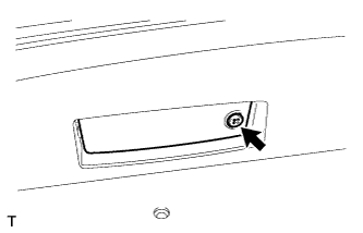
Install the back door opener switch assembly with the 2 screws.
5.0 N*m 51 kgf*cm 44 in.*lbf
-
- Click here
INSTALL LICENSE PLATE LIGHT LENS (for Standard)
-
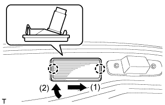
Connect the connector.
-
Attach the 2 claws in the order shown in the illustration to install the license plate light.
-
- Click here
INSTALL BACK DOOR CONTROL SWITCH (w/ Power Back Door)
-
Attach the 4 claws to install the back door control switch.
-
Connect the connector.
-
- Click here
INSTALL BACK DOOR LOCK PROTECTOR (w/ Power Back Door)
-
Attach the 2 claws to install the protector (A).
-
Attach the 7 claws to install the protector (B).
-
Install the screw.
-
- Click here
INSTALL BACK DOOR LOCK ASSEMBLY
-
w/o Power Back Door:
-
Install the back door lock assembly with the 3 bolts.
13 N*m 133 kgf*cm 10 ft.*lbf -
Connect the connector.
-
-
w/ Power Back Door:
-
Install the back door lock assembly with the 4 bolts.
13 N*m 133 kgf*cm 10 ft.*lbf -
Attach the guide.
-
Connect the connector.
-
-
- Click here
INSTALL BACK DOOR LOCK COVER
-
Attach the 4 claws to install the back door lock cover.
-
- Click here
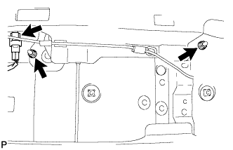
INSTALL REAR WIPER MOTOR ASSEMBLY (w/ Rear Wiper)
-
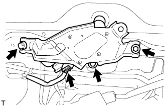
Temporarily install the rear wiper motor assembly with the 3 bolts.
-
Tighten the 3 bolts.
5.5 N*m 56 kgf*cm 49 in.*lbf -
Connect the connector.
-
- Click here
INSTALL REAR WIPER MOTOR GROMMET (w/ Rear Wiper)
-
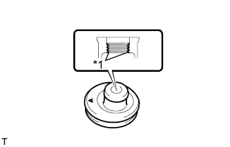
Apply MP grease to the entire inner surface of the rear wiper motor grommet.
Table 2. Text in Illustration *1 MP Grease Tip:Make sure that the hole does not get clogged with grease and the grooves in the grommet are filled with grease.
-
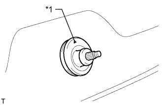
Install the rear wiper motor grommet with the position mark facing upward as shown in the illustration.
Table 3. Text in Illustration *1 Position Mark
-
- Click here
INSTALL REAR WIPER ARM (w/ Rear Wiper)
-
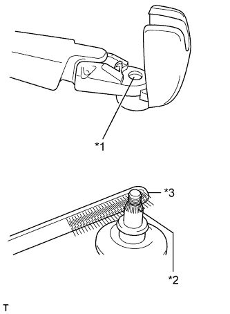
Operate the rear wiper, and stop the rear wiper motor at the automatic stop position.
Table 4. Text in Illustration *1 Wiper Arm Serration *2 Wiper Pivot Serration *3 Wire Brush -
Clean the wiper arm serration and wiper pivot serration with a wire brush.
-
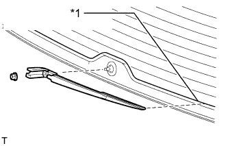
Set the head of the blade on the defogger line.
Table 5. Text in Illustration *1 Defogger Line -
Install the nut and rear wiper arm.
5.5 N*m 56 kgf*cm 49 in.*lbf -
Close the cover.
-
- Click here
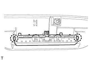
INSTALL POWER BACK DOOR SENSOR ASSEMBLY LH (w/ Power Back Door)
-
Attach the 2 clips to install the power back door sensor assembly LH.
-
Using a T25 "TORX" wrench, install the 6 screws.
-
Connect the connector.
-
- Click here
INSTALL POWER BACK DOOR SENSOR ASSEMBLY RH (w/ Power Back Door)
Tip:Use the same procedure described for the LH side.
- Click here
INSTALL REAR ASSIST GRIP REINFORCEMENT (for Face to Face Seat Type)
-
Attach the 2 claws to install the rear assist grip reinforcement.
-
Install the 3 bolts.
-
- Click here
INSTALL REAR HEADER SPEAKER ASSEMBLY (for 14 Speakers)
-
Connect the connector.
-
Install the rear header speaker assembly with the 3 screws.
-
- Click here
INSTALL BACK DOOR GARNISH
-
Attach the 14 clips to install the back door garnish.
-
- Click here
INSTALL DOOR OPENING SWITCH SUB-ASSEMBLY (for Face to Face Seat Type)
-
Attach the 2 claws to install the door opening switch sub-assembly.
-
- Click here
INSTALL NO. 2 BACK DOOR SERVICE HOLE COVER (for Face to Face Seat Type)
-
Connect the connector.
-
Attach the 4 claws to install the No. 2 back door service hole cover.
-
- Click here
INSTALL ASSIST GRIP (for Face to Face Seat Type)
-
Install the assist grip with the 2 screws.
-
- Click here
INSTALL BACK DOOR SERVICE HOLE COVER RH (w/ Power Back Door)
-
Install the back door stay plate.
-
Pass the power back door rod through the hole of the back door service hole cover RH and install the rod with the bolt.
18 N*m 184 kgf*cm 13 ft.*lbf -
Move the back door to a half-open position so that the hole in the center of the back door service hole cover RH is aligned lengthwise with the power back door rod.
-
Attach the 2 clips and install the back door service hole cover RH.
Note:If the back door is in a fully-open position, the power back door rod will interfere with the hole of the back door service hole cover, so do not perform this operation with the back door in a fully open position.
-
- Click here
INSTALL BACK DOOR SIDE GARNISH LH
-
Attach the 3 clips and 2 claws to install the back door side garnish LH.
-
- Click here
INSTALL BACK DOOR SIDE GARNISH RH
-
w/o Power Back Door:
Tip:Use the same procedure described for the LH side.
-
w/ Power Back Door:
-
Attach the clip and 4 claws to install the back door side garnish RH.
-
-
- Click here
INSTALL CENTER STOP LIGHT ASSEMBLY
-
Attach the 2 claws to install the stop light.
-
- Click here
INSTALL CENTER BACK DOOR GARNISH
-
Attach the 5 clips and 4 claws to install the center back door garnish.
-
- Click here
INSTALL LOWER BACK DOOR STOPPER CUSHION
-
Install the 2 lower back door stopper cushions with the 4 bolts.
-
- Click here
INSTALL BACK DOOR GRIP
-
Attach the claw.
-
Install the back door grip with the 2 screws.
-
Attach the 5 claws to close the cover.
-
- Click here
CONNECT CABLE TO NEGATIVE BATTERY TERMINAL
Note:When disconnecting the cable, some systems need to be initialized after the cable is reconnected (Click here).
- Click here
ADJUST REAR TELEVISION CAMERA ASSEMBLY
-
w/o Side Monitor System:
-
w/ Side Monitor System:
-