COMBINATION METER (w/ Multi-information Display) REMOVAL

-
DISABLE AUTO TILT AWAY FUNCTION
-
Disable the function by changing the customize parameter Click here.
Note
Record the current customize parameter setting (whether the Autoaway/Return function is enabled or disabled) in order to restore the current setting after finishing the operation.
Tech Tips
Performing the above operation causes the Autoaway/Return function to be disabled when the engine switch is turned off.
-
Turn the engine switch on (IG). Operate the tilt and telescopic switch to fully extend and lower the steering column assembly.
-
Turn the engine switch off.
-
-
PRECAUTION
Note
After turning the ignition switch off, waiting time may be required before disconnecting the cable from the battery terminal. Therefore, make sure to read the disconnecting the cable from the battery terminal notice before proceeding with work Click here.
-
DISCONNECT CABLE FROM NEGATIVE BATTERY TERMINAL
CAUTION:
Wait at least 90 seconds after disconnecting the cable from the negative (-) battery terminal to disable the SRS system.
Note
When disconnecting the cable, some systems need to be initialized after the cable is reconnected Click here.
-
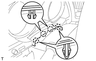
REMOVE NO. 1 INSTRUMENT CLUSTER FINISH PANEL GARNISH
-
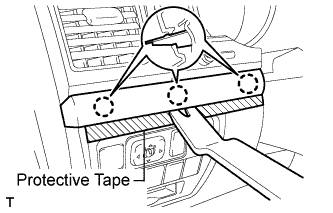
Place protective tape as shown in the illustration.
-
Using a moulding remover, detach the 3 claws and remove the panel garnish.
-
-
REMOVE NO. 2 INSTRUMENT PANEL FINISH PANEL CUSHION
-
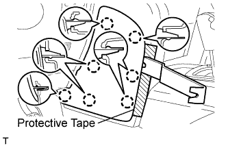
Place protective tape as shown in the illustration.
-
Using a moulding remover, detach the 7 claws and remove the panel cushion.
-
-
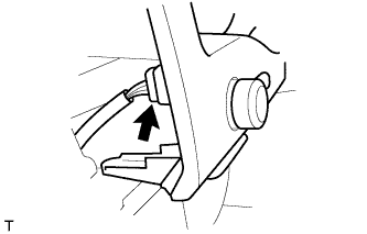
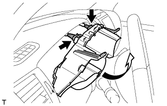
REMOVE LOWER INSTRUMENT PANEL PAD SUB-ASSEMBLY LH
-
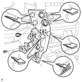
Remove the clip.
-
Remove the screw.
-
Detach the 8 claws.
-
Remove the panel pad and disconnect the connectors and 2 clamps.
-
-
REMOVE NO. 2 INSTRUMENT CLUSTER FINISH PANEL GARNISH
-
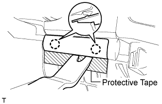
Place protective tape as shown in the illustration.
-
Using a moulding remover, detach the 2 claws and remove the panel garnish.
-
-
REMOVE INSTRUMENT CLUSTER FINISH PANEL SUB-ASSEMBLY
-
Detach the 4 claws.
-
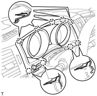
Detach the 9 claws.
-
Remove the finish panel and disconnect the connector.
-
-
REMOVE COMBINATION METER ASSEMBLY
-
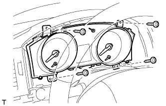
Remove the 4 screws.
-
Disconnect the connectors, and remove the combination meter by pulling it up in the direction of the arrow in the illustration.
-