METER / GAUGE SYSTEM Engine Coolant Temperature Gauge Malfunction
DESCRIPTION
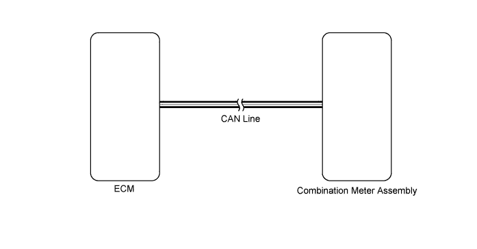
In this circuit, the combination meter assembly receives engine coolant temperature signals from the ECM using CAN communication lines. The combination meter assembly displays an engine coolant temperature that is calculated based on the data received from the ECM.
WIRING DIAGRAM
INSPECTION PROCEDURE
Tech Tips
If there is an open or short in the engine coolant temperature sensor circuit, an SFI system DTC is output. If output, perform troubleshooting on the SFI system first.
PROCEDURE
-
CHECK CAN COMMUNICATION SYSTEM
-
Check for DTCs Click here.
Result Result Proceed to CAN communication system DTC is not output A CAN communication system (for LHD) DTC is output B CAN communication system (for RHD) DTC is output C
B 
Go to CAN COMMUNICATION SYSTEM Click here
C
Go to CAN COMMUNICATION SYSTEM Click here
A 
-
-
PERFORM ACTIVE TEST USING INTELLIGENT TESTER (COOLANT TEMP)
-
Operate the intelligent tester according to the display and select Active Test.
Combination Meter Tester Display Test Part Control Range Diagnostic Note Water Temperature Meter Operation Engine coolant temperature receiver gauge LOW, NORMAL or HIGH Perform the test with the vehicle stopped and engine idling. Tech Tips
Confirm that the vehicle is stopped and the engine is idling.
OK Needle indication is normal. Result Result Proceed to OK A NG (w/ Multi-information Display) B NG (w/o Multi-information Display) C
B
REPLACE COMBINATION METER ASSEMBLY Click here
C
REPLACE COMBINATION METER ASSEMBLY Click here
A
-
-
READ VALUE USING INTELLIGENT TESTER (COOLANT TEMPERATURE)
-
Operate the intelligent tester according to the display and select Data List.
Combination Meter Tester Display Measurement Item/Range Normal Condition Diagnostic Note Coolant Temperature Engine coolant temperature/Min.: -40 (-40), Max.: 140 (284) After warming up: 80 to 105 (176 to 221)
-
Unit: °C (°F)
-
If the value is -40 (-40): The sensor circuit is open
-
If the value is 140 (284): The sensor circuit is shorted.
OK Coolant temperature displayed on the intelligent tester is between 80°C (176°F) and 95°C (203°F) after warming up. Result Result
Proceed to OK A NG (w/ Multi-information Display) B NG (w/o Multi-information Display) C -
B
REPLACE COMBINATION METER ASSEMBLY Click here
C
REPLACE COMBINATION METER ASSEMBLY Click here
A
-
-
READ VALUE USING INTELLIGENT TESTER (ENGINE COOLANT)
-
Operate the intelligent tester according to the display and select Data List.
Engine*1, *2, *3 Tester Display Measurement Item/Range Normal Condition Diagnostic Note Coolant Temp Engine coolant temperature:
Min.: -40°C, Max.:140°C
80 to 100°C (176 to 212°F):
After warming up
-
If the value is -40°C (-40°F), the sensor circuit is open.
-
If the value is 140°C (284°F), the sensor circuit is shorted.
Engine*4 Tester Display Measurement Item/Range Normal Condition Diagnostic Note Coolant Temp Engine coolant temperature/
Min.: -40°C, Max.:140°C
After warming up engine: 75 to 90°C (167 to 194°F)
-
If the value is -40°C (-40°F) or 140°C (284°F), the sensor circuit is open or shorted.
-
After a long soak, the coolant temperature, intake air temperature, and ambient air temperature are approximately equal.
-
*1: for 1GR-FE
-
*2: for 1UR-FE
-
*3: for 3UR-FE
-
*4: for 1VD-FTV
OK Engine coolant temperature value displayed on the intelligent tester is almost the same as actual engine coolant temperature. Result Result Proceed to OK A NG (for 1GR-FE) B NG (for 1UR-FE) C NG (for 3UR-FE) D NG (for 1VD-FTV) E -
B
Go to SFI SYSTEM Click here
C
Go to SFI SYSTEM Click here
D
Go to SFI SYSTEM Click here
E
Go to ECD SYSTEM Click here
A
-
-
REPLACE COMBINATION METER ASSEMBLY
-
w/ Multi-information Display:
-
Temporarily replace the combination meter with a new one Click here.
-
-
w/o Multi-information Display:
-
Temporarily replace the combination meter with a new one Click here.
-
NEXT
-
-
CHECK COMBINATION METER ASSEMBLY
-
w/ Multi-information Display:
-
Check that the operation of the combination meter returns to normal Click here.
-
-
w/o Multi-information Display:
-
Check that the operation of the combination meter returns to normal Click here.
OK Operation of combination meter returns to normal. Result Result Proceed to OK A NG (for 1GR-FE) B NG (for 1UR-FE) C NG (for 3UR-FE) D NG (for 1VD-FTV) E -
B
REPLACE ECM Click here
C
REPLACE ECM Click here
D
REPLACE ECM Click here
E
REPLACE ECM Click here
A 
END (COMBINATION METER IS DEFECTIVE)
-