-
Use the same procedures for the LH side and RH side.
-
The procedures listed below are for the LH side.
- Click here
INSTALL REAR DOOR OUTSIDE HANDLE ASSEMBLY LH
-
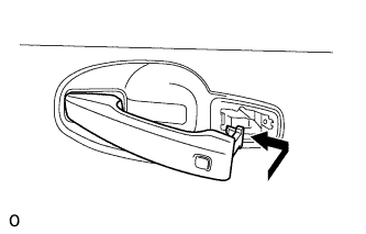
Insert the front end of the rear door outside handle assembly into the rear door outside handle frame.
Note:If the bellcrank lever is not pulled and held when installing the outside handle, the bellcrank lever will interfere with the outside handle and the release plate may be damaged.
-
Insert the rear end of the rear door outside handle assembly into the rear door outside handle frame. Next, slide the rear door outside handle assembly toward the front of the vehicle to install it.
-
Using a T30 ''TORX'' socket, tighten the screw.
-
Connect the connector.
-
- Click here
INSTALL REAR DOOR OUTSIDE HANDLE COVER LH
-
Attach the claw to install the rear door outside handle cover LH.
-
Using a T30 ''TORX'' socket, install the rear door outside handle cover LH with the screw.
-
- Click here
INSTALL REAR DOOR LOCK ASSEMBLY LH
-
Apply MP grease to the sliding parts of the rear door lock assembly.
-
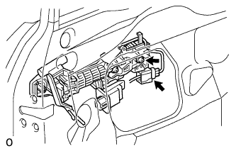
Insert the rear door lock assembly to the rear door outside handle release plate, and set it to the rear door panel.
-
Make sure that the rear door outside handle frame release plate is securely connected to the rear door lock assembly.
-
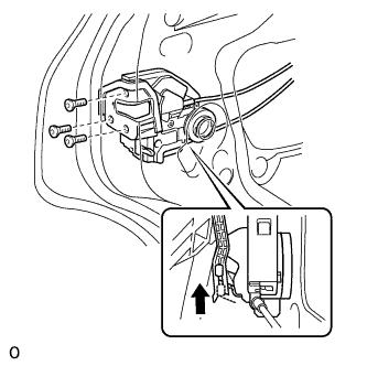
Using a T30 ''TORX'' wrench, the 3 screws.
5.0 N*m 51 kgf*cm 44 in.*lbf
-
- Click here
INSTALL REAR DOOR SERVICE HOLE COVER LH
-
Apply butyl tape to the door.
-
Pass the rear door lock remote control cable assembly LH and rear door inside locking cable assembly LH through a new rear door service hole cover LH.
Note:
-
When installing the rear door service hole cover LH, pull the links and connectors through the rear door service hole cover LH.
-
There should be no wrinkles or folds after attaching the rear door service hole cover LH.
-
After attaching the rear door service hole cover LH, check the sealing quality.
-
-
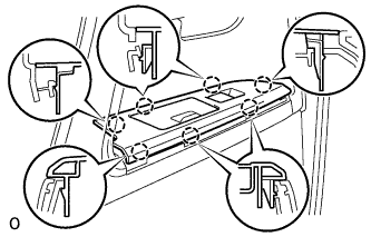
Connect the 2 connectors.
-
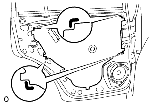
Attach the 6 clamps.
-
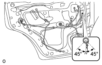
Install the bolt as shown in the illustration.
8.4 N*m 86 kgf*cm 74 in.*lbf
-
- Click here
INSTALL COURTESY LIGHT ASSEMBLY (w/ Courtesy Light)
-
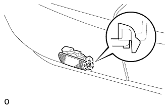
Connect the connector.
-
Attach the claw of the courtesy light to the rear door trim.
-
- Click here
INSTALL REAR DOOR TRIM BOARD SUB-ASSEMBLY LH
-
Connect the connector.
-
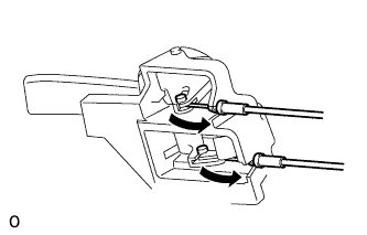
Connect the rear door lock remote control cable assembly LH and rear door inside locking cable assembly LH to the rear door inside handle sub-assembly LH.
-
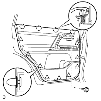
Attach the 4 claws and 9 clips to install the rear door trim board sub-assembly LH.
-
Install the 3 screws.
-
- Click here
INSTALL ASSIST GRIP COVER LH
-
Attach the 9 claws to install the assist grip cover LH to the rear door trim board sub-assembly LH.
-
- Click here
INSTALL REAR DOOR INSIDE HANDLE BEZEL LH
-
Attach the 4 claws to install the rear door inside handle bezel LH.
-
- Click here
INSTALL REAR DOOR ARMREST BASE PANEL ASSEMBLY LH
-
Connect the connector.
-
Attach the 7 claws to install the armrest base panel.
-
- Click here
CONNECT CABLE TO NEGATIVE BATTERY TERMINAL
Note:When disconnecting the cable, some systems need to be initialized after the cable is reconnected (Click here).