ENTRY LOCK AND UNLOCK SWITCH (for Rear) REMOVAL

Tech Tips
-
Use the same procedures for the LH side and RH side.
-
The procedures listed below are for the LH side.
-
DISCONNECT CABLE FROM NEGATIVE BATTERY TERMINAL
Note
When disconnecting the cable, some systems need to be initialized after the cable is reconnected Click here.
-
REMOVE REAR DOOR ARMREST BASE PANEL ASSEMBLY LH
-
Using a moulding remover, detach the 7 claws.
-
Disconnect the connector and remove the armrest base panel.
-
-
REMOVE REAR DOOR INSIDE HANDLE BEZEL LH
-
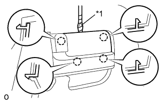
Text in Illustration *1 Protective Tape Using a screwdriver, detach the 4 claws and remove the rear door inside handle bezel LH.
Tech Tips
Tape the screwdriver tip before use.
-
-
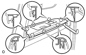
REMOVE ASSIST GRIP COVER LH
-
Using a moulding remover, detach the 9 claws and remove the assist grip cover LH.
-
-
REMOVE COURTESY LIGHT ASSEMBLY (w/ Courtesy Light)
-
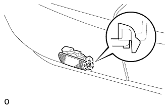
Detach the claw.
-
Remove the courtesy light and then disconnect the connector.
-
-
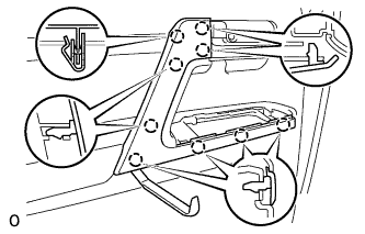
REMOVE REAR DOOR TRIM BOARD SUB-ASSEMBLY LH
-
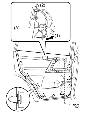
Remove the 3 screws.
-
Remove the 9 clips.
-
Remove the rear inner door glass weatherstrip LH together with the rear door trim board sub-assembly LH by pulling them upward in the order shown in the illustration.
Tech Tips
Make sure that the pin labeled A in the illustration is detached from the door panel.
-
Disconnect the connector and remove the rear door trim board sub-assembly LH.
-
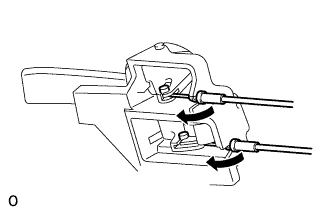
Disconnect the 2 cables from the rear door inside handle sub-assembly LH.
-
-
REMOVE REAR DOOR SERVICE HOLE COVER LH
-
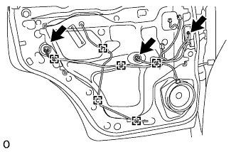
Using a clip remover, detach the 6 clamps.
-
Remove the bolt and disconnect the 2 connectors.
-
Remove the rear door service hole cover LH.
Tech Tips
Remove the remaining tape on the door.
-
-
REMOVE REAR DOOR LOCK ASSEMBLY LH
-
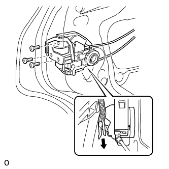
Using a T30 ''TORX'' socket, remove the 3 screws and door lock.
Note
Be careful when removing the screws as the door lock may fall and become damaged.
-
-
REMOVE REAR DOOR OUTSIDE HANDLE COVER LH
-
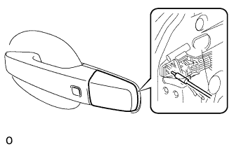
Using a T30 ''TORX'' socket, loosen the screw.
-
Detach the claw and remove the rear door outside handle cover LH.
-
-
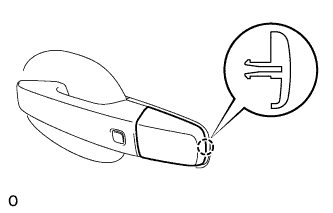
REMOVE REAR DOOR OUTSIDE HANDLE ASSEMBLY LH
-
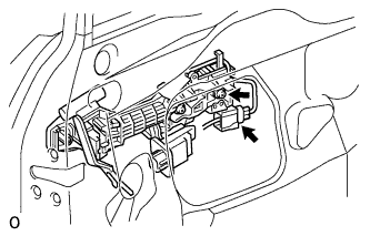
Using a T30 "TORX" wrench, loosen the screw.
-
Disconnect the connector.
-
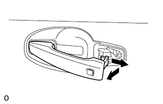
Remove the handle by sliding and pulling it in the direction indicated by the arrow in the illustration.
-