ENTRY AND START SYSTEM (for Start Function), Diagnostic DTC:B2275

| DTC Code | DTC Name |
|---|---|
| B2275 | STSW Monitor Malfunction |
DESCRIPTION
This DTC is stored when the engine start request signal circuit inside the main body ECU is open or shorted.
| DTC Code | Detection Condition | Trouble Area |
|---|---|---|
| B2275 | The engine start request signal circuit inside the main body ECU or other related circuit is malfunctioning. |
|
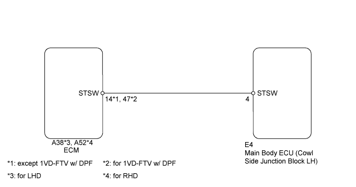
WIRING DIAGRAM
INSPECTION PROCEDURE
PROCEDURE
-
CHECK WHETHER DTC OUTPUT RECURS
-
Clear the DTCs Click here.
-
Depress the brake pedal (for A/T) or clutch pedal (for M/T) with the engine switch on (IG), wait at least 15 seconds, and check whether DTC B2275 is output.
Result Result Proceed to DTC B2275 output A No DTC output B
B 
USE SIMULATION METHOD TO CHECK Click here
A 
-
-
CHECK HARNESS AND CONNECTOR (MAIN BODY ECU - ECM)
-
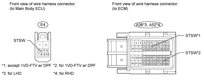
Disconnect the E4 main body ECU connector.
-
Disconnect the A38 (for LHD) or A52 (for RHD) ECM connector.
-
Measure the resistance according to the value(s) in the table below.
Standard Resistance (except 1VD-FTV w/ DPF) Tester Connection Condition Specified Condition E4-4 (STSW) - A38-14 (STSW)*1
E4-4 (STSW) - A52-14 (STSW)*2
Always Below 1 Ω E4-4 (STSW) or A38-14 (STSW) - Body ground*1
E4-4 (STSW) or A52-14 (STSW) - Body ground*2
Always 10 kΩ or higher Tech Tips
*1: for LHD
*2: for RHD
Standard Resistance (for 1VD-FTV w/ DPF) Tester Connection Condition Specified Condition E4-4 (STSW) - A38-47 (STSW)*1
E4-4 (STSW) - A52-47 (STSW)*2
Always Below 1 Ω E4-4 (STSW) or A38-47 (STSW) - Body ground*1
E4-4 (STSW) or A52-47 (STSW) - Body ground*2
Always 10 kΩ or higher Tech Tips
*1: for LHD
*2: for RHD
NG
REPAIR OR REPLACE HARNESS OR CONNECTOR
OK
-
-
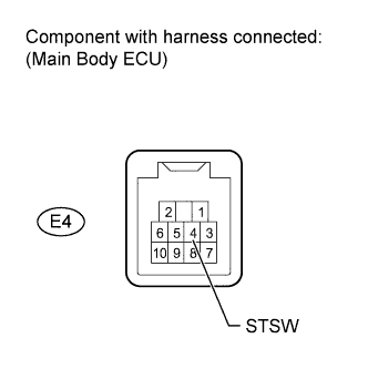
INSPECT MAIN BODY ECU
-
Measure the voltage according to the value(s) in the table below.
Tech Tips
The voltage is generated at terminal STSW for 0.3 seconds when the engine cranks.
Standard Voltage (for A/T) Tester Connection Condition Specified Condition E4-4 (STSW) - Body ground Brake pedal depressed with shift lever in P, engine switch pushed once 11 to 14 V Standard Voltage (for M/T) Tester Connection Condition Specified Condition E4-4 (STSW) - Body ground Clutch pedal depressed, engine switch pushed once 11 to 14 V Result Result Proceed to Outside specified range A Within specified range (for 1GR-FE) B Within specified range (for 1UR-FE) C Within specified range (for 3UR-FE) D Within specified range (for 1VD-FTV) E
B
REPLACE ECM Click here
C
REPLACE ECM Click here
D
REPLACE ECM Click here
E
REPLACE ECM Click here
A 
REPLACE MAIN BODY ECU
-