UNLOCK WARNING SWITCH REMOVAL

-
PRECAUTION
Note
After turning the ignition switch off, waiting time may be required before disconnecting the cable from the battery terminal. Therefore, make sure to read the disconnecting the cable from the battery terminal notice before proceeding with work Click here.
-
DISCONNECT CABLE FROM NEGATIVE BATTERY TERMINAL
Note
When disconnecting the cable, some systems need to be initialized after the cable is reconnected Click here.
-
REMOVE LOWER STEERING COLUMN COVER
-
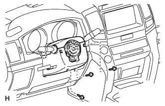
Remove the 3 screws.
-
Detach the 2 claws to remove the lower steering column cover.
Note
Do not damage the tilt and telescopic switch.
-
-
REMOVE UPPER STEERING COLUMN COVER
-
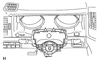
Detach the 4 clips.
-
Detach the claw to remove the upper steering column cover.
-
-
REMOVE TRANSPONDER KEY AMPLIFIER
-
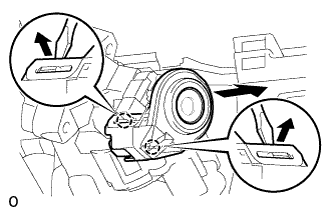
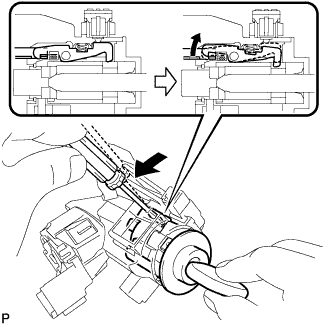
Using a screwdriver, widen the claw attached to the upper bracket by approximately 1.0 mm (0.039 in.).
-
Pull out the transponder key amplifier with the claw open.
-
Disconnect the connector and remove the transponder key amplifier.
-
-
REMOVE IGNITION SWITCH LOCK CYLINDER ASSEMBLY
-
Turn the ignition switch lock cylinder assembly to ACC.
-
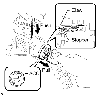
Insert a thin-bladed screwdriver into the hole of the steering column upper bracket assembly as shown in the illustration and pull out the key until the claw of the ignition switch lock cylinder assembly contacts the stopper of the steering column upper bracket assembly.
Note
Be sure to pull out the key until the claw firmly contacts the stopper. There will be problems later if the key is not pulled out until the claw of the ignition switch lock cylinder assembly contacts the stopper of the steering column upper bracket assembly.
-
Insert a thin-bladed screwdriver into the hole of the steering column upper bracket assembly as shown in the illustration, push the thin-bladed screwdriver in the direction shown in the illustration to detach the claw and pull out the ignition switch lock cylinder assembly.
-
-
REMOVE UNLOCK WARNING SWITCH ASSEMBLY
-
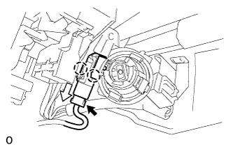
Disconnect the unlock warning switch connector.
-
Detach the 2 claws and slide the unlock warning switch as shown in the illustration.
-
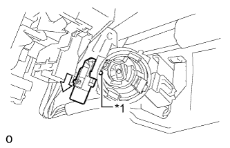
Text in Illustration *1 Pin Push in the pin, slide the unlock warning switch as shown in the illustration and remove it.
-