FRONT AND SIDE MONITOR MAIN SWITCH INSTALLATION

Tech Tips
-
Use the same procedure for RHD and LHD vehicles.
-
The procedure listed below is for LHD vehicles.
-
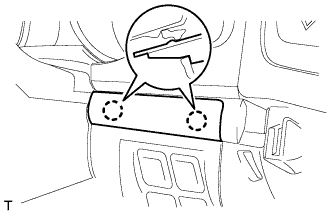
INSTALL MAIN SWITCH ASSEMBLY
-
Attach the 2 claws to install the main switch assembly.
-
-
INSTALL INSTRUMENT CLUSTER FINISH PANEL SUB-ASSEMBLY
-
w/o Multi-information Display:
Connect the connector.
-
w/ Multi-information Display:
Connect the 2 connectors.
-
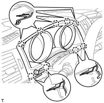
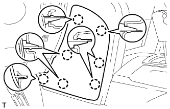
Attach the 9 claws to install the finish panel.
-
Attach the 4 claws.
-
-
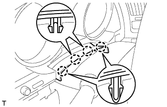
INSTALL NO. 2 INSTRUMENT CLUSTER FINISH PANEL GARNISH
-
Attach the 2 claws to install the panel garnish.
-
-
INSTALL LOWER INSTRUMENT PANEL PAD SUB-ASSEMBLY LH
-
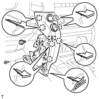
Connect the connectors and 2 clamps.
-
Attach the 8 claws to install the panel pad.
-
Install the screw.
-
Install the clip.
-
-
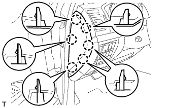
INSTALL NO. 2 INSTRUMENT PANEL FINISH PANEL CUSHION
-
Attach the 7 claws to install the panel cushion.
-
-
INSTALL NO. 1 INSTRUMENT CLUSTER FINISH PANEL GARNISH
-
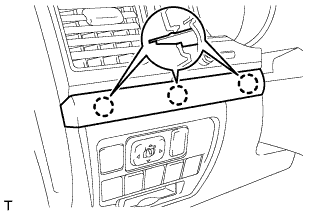
Attach the 3 claws to install the panel garnish.
-
-
INSTALL INSTRUMENT SIDE PANEL LH
-
Attach the 6 claws to install the instrument side panel.
-
-
CONNECT CABLE TO NEGATIVE BATTERY TERMINAL
Note
-
Reset the Autoaway/Return function setting to the previous condition by changing the customize parameter Click here.
-
When disconnecting the cable, some systems need to be initialized after the cable is reconnected Click here.
-