-
Use the same procedure for RHD and LHD vehicles.
-
The procedure listed below is for LHD vehicles.
- Click here
DISABLE AUTO TILT AWAY FUNCTION
-
Disable the function by changing the customize parameter (Click here).
Note:Record the current customize parameter setting (whether the Autoaway/Return function is enabled or disabled) in order to restore the current setting after finishing the operation.
Tip:Performing the above operation causes the Autoaway/Return function to be disabled when the engine switch is turned off.
-
Turn the engine switch on (IG). Operate the tilt and telescopic switch to fully extend and lower the steering column assembly.
-
Turn the engine switch off.
-
- Click here
DISCONNECT CABLE FROM NEGATIVE BATTERY TERMINAL
CAUTION:Wait at least 90 seconds after disconnecting the cable from the negative (-) battery terminal to disable the SRS system.
Note:When disconnecting the cable, some systems need to be initialized after the cable is reconnected (Click here).
-
Click here
REMOVE INSTRUMENT SIDE PANEL LH
-
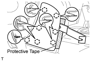
Place protective tape as shown in the illustration.
Table 1. Text in Illustration *1 Protective Tape -
Using a moulding remover, detach the 6 claws and remove the instrument side panel.
-
-
Click here
REMOVE NO. 1 INSTRUMENT CLUSTER FINISH PANEL GARNISH
-
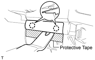
Place protective tape as shown in the illustration.
Table 2. Text in Illustration *1 Protective Tape -
Using a moulding remover, detach the 3 claws and remove the No. 1 instrument cluster finish panel garnish.
-
- Click here
REMOVE NO. 2 INSTRUMENT PANEL FINISH PANEL CUSHION
-
Place protective tape as shown in the illustration.
-
Using a moulding remover, detach the 7 claws and remove the panel cushion.
-
- Click here
REMOVE LOWER INSTRUMENT PANEL PAD SUB-ASSEMBLY LH
-
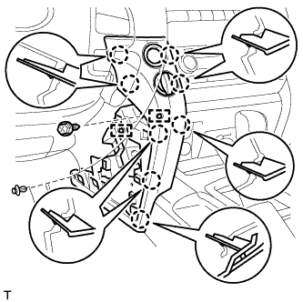
Remove the clip.
-
Remove the screw.
-
Detach the 8 claws.
-
Remove the panel pad and disconnect the connectors and 2 clamps.
-
- Click here
REMOVE NO. 2 INSTRUMENT CLUSTER FINISH PANEL GARNISH
-
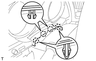
Place protective tape as shown in the illustration.
-
Using a moulding remover, detach the 2 claws and remove the panel garnish.
-
- Click here
REMOVE INSTRUMENT CLUSTER FINISH PANEL SUB-ASSEMBLY
-
Detach the 4 claws.
-
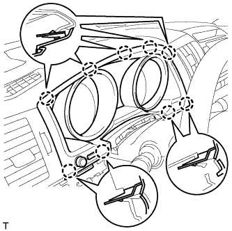
Detach the 9 claws.
-
w/ Multi-information Display:
Remove the finish panel and disconnect the 2 connectors.
-
w/o Multi-information Display:
Remove the finish panel and disconnect the connector.
-
- Click here
REMOVE MAIN SWITCH ASSEMBLY
-
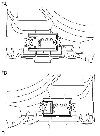
Detach the 2 claws and remove the main switch assembly.
Table 3. Text in Illustration *A for LHD *B for RHD
-