VANE PUMP (for 1VD-FTV without DPF) INSTALLATION

-
INSTALL VANE PUMP ASSEMBLY
-
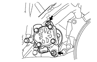
Coat a new O-ring with power steering fluid and install it to the vane pump.
-
Install the vane pump with the 2 nuts.
- Torque:
- 29 N*m { 296 kgf*cm, 21 ft.*lbf }
-
-
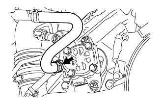
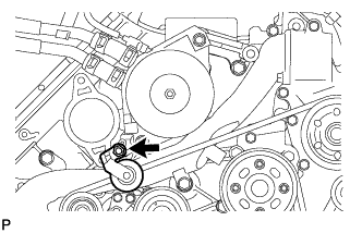
CONNECT PRESSURE FEED TUBE ASSEMBLY
-
Install a new gasket to the pressure feed tube.
-
Install the pressure feed tube and union with the union bolt.
- Torque:
- 50 N*m { 510 kgf*cm, 37 ft.*lbf }
Tech Tips
Make sure that the stopper of the tube touches the vane pump body as shown in the illustration before tightening the bolt.
-
-
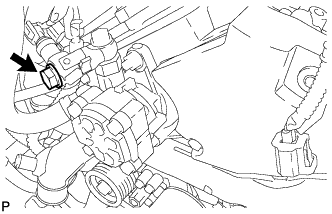
CONNECT POWER STEERING OIL PRESSURE SWITCH CONNECTOR
-
Connect the connector.
-
-
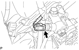
CONNECT NO. 1 OIL RESERVOIR TO PUMP HOSE
-
Connect the pump hose to the vane pump with the clip.
-
-
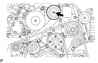
INSTALL V-RIBBED BELT
-
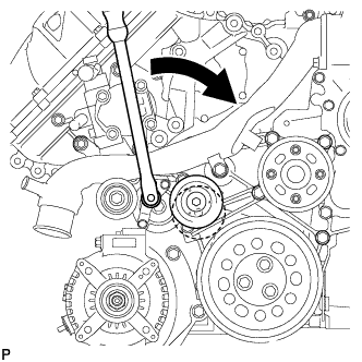
Attach a wrench to the V-ribbed belt tensioner bracket and turn the wrench clockwise.
-
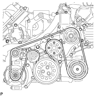
Install the V-ribbed belt as shown in the illustration.
-
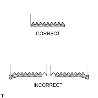
Check that the belt fits properly in the ribbed grooves.
Tech Tips
Check with your hand to confirm that the belt has not slipped out of the groove on the bottom of the pulley.
If it has slipped out, replace the V-ribbed belt. Install a new V-ribbed belt.
-
-
INSTALL NO. 3 IDLER PULLEY (w/ Viscous Heater)
-
Align the No. 3 idler pulley bracket knock pin and No. 1 idler pulley bracket knock pin hole and install the No. 3 idler pulley with the nut.
- Torque:
- 88 N*m { 898 kgf*cm, 64 ft.*lbf }
-
-
INSTALL NO. 1 IDLER PULLEY (w/ Viscous Heater)
-
Install the collar, No. 1 idler pulley and cover with the bolt.
- Torque:
- 49 N*m { 495 kgf*cm, 36 ft.*lbf }
-
-
INSTALL V-RIBBED BELT (w/ Viscous Heater)
-
Install the collar, No. 1 idler pulley and cover with the bolt.
- Torque:
- 49 N*m { 495 kgf*cm, 36 ft.*lbf }
-
-
INSTALL RADIATOR RESERVOIR ASSEMBLY
-
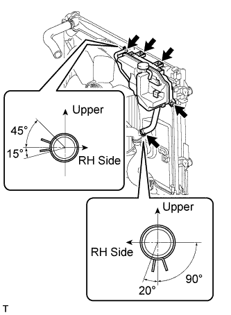
Install the radiator reservoir with the 3 bolts.
-
Connect the 2 hoses to the upper radiator tank and water inlet.
Tech Tips
Make sure the directions of the hose clamps are as shown in the illustration.
-
-
INSTALL INTAKE AIR CONNECTOR
-
Connect the intake air connector to the No. 1 and No. 2 air cleaner pipes.
-
Install the connector with the 2 bolts.
- Torque:
- 21 N*m { 214 kgf*cm, 15 ft.*lbf }
-
Tighten the 2 hose clamps.
- Torque:
- 6.3 N*m { 64 kgf*cm, 56 in.*lbf }
-
Attach the 3 wire harness clamps.
-
w/o Viscous Heater:
Connect the connector to the water temperature sensor.
-
w/ Viscous Heater:
Connect the 2 connectors to the water temperature sensor and viscous with magnet clutch heater.
-
-
TEMPORARILY INSTALL NO. 1 AIR CLEANER HOSE
-
Temporarily install the air cleaner hose to the intake air connector.
-
-
INSTALL AIR CLEANER CAP SUB-ASSEMBLY
-
Connect the air cleaner cap to the air cleaner hose, and install the air cleaner cap with the 4 clamps.
-
Connect the mass air flow meter connector and attach the wire harness clamp to the air cleaner cap.
-
Attach the wire harness clamp.
-
Align the protrusion of the air cleaner cap and the concave portion of the air cleaner hose.
-
Tighten the 2 hose clamps.
- Torque:
- 2.5 N*m { 25 kgf*cm, 22 in.*lbf }
-
-
INSTALL NO. 1 ENGINE COVER SUB-ASSEMBLY
-
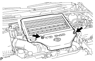
Install the engine cover with the 2 nuts.
- Torque:
- 8.0 N*m { 82 kgf*cm, 71 in.*lbf }
-
-
INSTALL UPPER RADIATOR SUPPORT SEAL
-
Install the upper radiator support seal with the 7 clips.
-
-
INSTALL FRONT FENDER APRON TRIM PACKING A
-
Install the front fender apron seal front RH with the 3 clips.
-
-
ADD POWER STEERING FLUID
-
BLEED POWER STEERING FLUID
-
INSPECT FOR POWER STEERING FLUID LEAK
-
CONNECT CABLE TO NEGATIVE BATTERY TERMINAL
Note
When disconnecting the cable, some systems need to be initialized after the cable is reconnected Click here.