REAR UPPER ARM INSTALLATION

Tech Tips
-
Use the same procedures for the RH side and LH side.
-
The procedures listed below are for the LH side.
-
A bolt without a torque specification is shown in the standard bolt chart Click here.
-
TEMPORARILY INSTALL REAR UPPER CONTROL ARM ASSEMBLY LH (w/ Active Height Control)
-
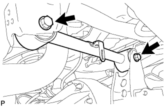
Temporarily install the rear upper control arm and 2 washers with the 2 bolts and 2 nuts.
-
-
TEMPORARILY INSTALL REAR UPPER CONTROL ARM ASSEMBLY LH (w/o Active Height Control)
-
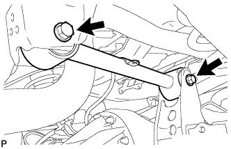
Temporarily install the rear upper control arm and 2 washers with the 2 bolts and 2 nuts.
-
-
STABILIZE SUSPENSION
-
Install the rear wheels.
- Torque:
- for aluminum wheel
- 131 N*m { 1336 kgf*cm, 97 ft.*lbf }
- for steel wheel
- 209 N*m { 2131 kgf*cm, 154 ft.*lbf }
-
Lower the vehicle.
-
Press down on the vehicle several times to stabilize the suspension.
-
-
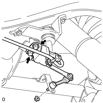
TIGHTEN REAR UPPER CONTROL ARM ASSEMBLY LH
-
Tighten the 2 nuts.
- Torque:
- 150 N*m { 1530 kgf*cm, 111 ft.*lbf }
Note
Perform this procedure with all 4 wheels on the ground.
-
-
INSTALL REAR STABILIZER CONTROL TUBE INSULATOR (w/ KDSS)
-
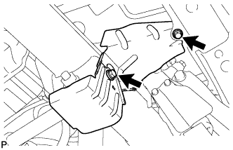
Install the rear stabilizer control tube insulator with the 2 bolts.
- Torque:
- 18 N*m { 184 kgf*cm, 13 ft.*lbf }
-
-
INSTALL UPPER ARM BUSH HEAT INSULATOR (w/o KDSS)
-
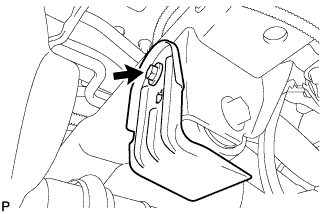
Install the upper arm bush heat insulator with the bolt.
- Torque:
- 18 N*m { 184 kgf*cm, 13 ft.*lbf }
-
-
CONNECT SPEED SENSOR WIRE HARNESS
-
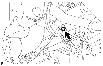
Connect the speed sensor wire harness with the bolt.
- Torque:
- 13 N*m { 127 kgf*cm, 9 ft.*lbf }
-
-
INSTALL REAR HEIGHT CONTROL SENSOR SUB-ASSEMBLY LH (w/ Active Height Control)
-
Install the sensor with the 2 bolts and nut.
- Torque:
- for bolt
- 13 N*m { 127 kgf*cm, 9 ft.*lbf }
- for nut
- 5.6 N*m { 57 kgf*cm, 50 in.*lbf }
-
Connect the connector and 2 clamps.
-
-
CONNECT CABLE TO NEGATIVE BATTERY TERMINAL (w/ Active Height Control)
Note
When disconnecting the cable, some systems need to be initialized after the cable is reconnected Click here.
-
PERFORM VEHICLE OFF SET CALIBRATION (w/ Active Height Control)
-
Perform the vehicle off set calibration Click here.
-
-
ADJUST REAR HEIGHT CONTROL SENSOR SUB-ASSEMBLY LH (w/ Active Height Control)
Note
-
Make adjustments from the link that deviates the most from the specified vehicle height value.
-
When the front and rear are at the same level, make adjustments from the front first.
-
If adjustment cannot be completed through the vehicle height offset calibration, adjust the sensor link using the following procedure.
-
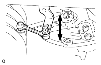
Loosen the nut and adjust the link installation position by moving the height control sensor link up or down in the long hole of the bracket.
Tech Tips
When the link is moved 1 mm (0.0394 in.), the vehicle height changes by approximately 2 mm (0.0787 in.).
-
Tighten the nut of the height control sensor link.
- Torque:
- 5.6 N*m { 57 kgf*cm, 50 in.*lbf }
-
-
MEASURE VEHICLE HEIGHT (w/ KDSS)
Note
-
Perform the inspection on a level surface.
-
Ensure that the wheels are on the ground and facing straight ahead.
-
Perform the inspection with the vehicle load completely on the suspension.
Tech Tips
-
Perform this step with the fuel tank full.
-
If there are any parts installed to the vehicle which place any unbalanced load on the left or right side of the vehicle, remove them.
-
Set the tire pressure to the specified value(s) Click here.
-
Bounce the vehicle to stabilize the suspension.
-
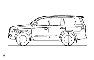
Measure the distance from the ground to the top of the bumper and calculate the difference in the vehicle height between left and right. Perform this procedure for both the front and rear wheels.
Height difference of left and right sides 15 mm (0.591 in.) or less Tech Tips
If not as specified, perform the vehicle tilt calibration.
-
-
CLOSE STABILIZER CONTROL WITH ACCUMULATOR HOUSING SHUTTER VALVE (w/ KDSS)
Note
-
Perform the inspection on a level surface.
-
Ensure that the wheels are on the ground and facing straight ahead.
-
Perform the inspection with the vehicle load completely on the suspension.
Tech Tips
-
Perform this step with the fuel tank full.
-
If there are any parts installed to the vehicle which place any unbalanced load on the left or right side of the vehicle, remove them.
-
Using a 5 mm hexagon socket wrench, tighten the lower and upper chamber shutter valves of the stabilizer control with accumulator housing.
- Torque:
- 14 N*m { 143 kgf*cm, 10 ft.*lbf }
-
-
INSTALL STABILIZER CONTROL VALVE PROTECTOR (w/ KDSS)
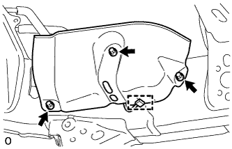
-
Install the valve protector with the 3 bolts.
- Torque:
- 18 N*m { 184 kgf*cm, 13 ft.*lbf }
-
Attach the clamp, and connect the connector to the valve protector.
-
-
ADJUST HEADLIGHT ASSEMBLY (w/ Active Height Control)
-
for Standard:
Adjust the headlight Click here.
-
for HID:
Adjust the headlight Click here.
-