FRONT ACCELERATION SENSOR REMOVAL

-
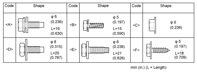
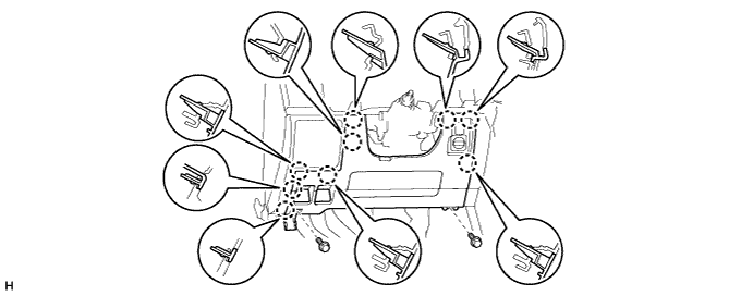
TABLE OF BOLT, SCREW AND NUT
Tech Tips
All bolts, screws and nuts relevant to installing and removing the instrument panel are shown along with their alphabet code in the table below.
-
DISCONNECT CABLE FROM NEGATIVE BATTERY TERMINAL
Note
When disconnecting the cable, some systems need to be initialized after the cable is reconnected Click here.
-
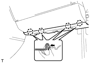
REMOVE NO. 2 INSTRUMENT PANEL FINISH PANEL CUSHION
-
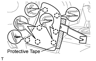
Place protective tape as shown in the illustration.
-
Using a moulding remover, detach the 7 claws and remove the panel cushion.
-
-
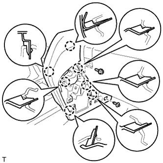
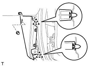
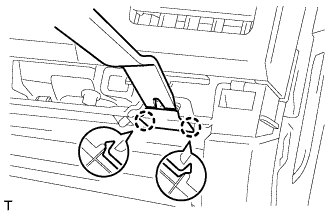
REMOVE LOWER INSTRUMENT PANEL PAD SUB-ASSEMBLY LH
-
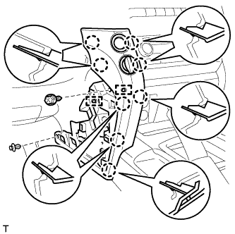
Remove the clip.
-
Remove the screw.
-
Detach the 8 claws.
-
Remove the panel pad and disconnect the connectors and 2 clamps.
-
-
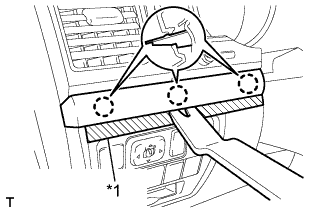
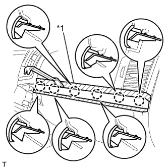
REMOVE NO. 1 INSTRUMENT PANEL FINISH PANEL CUSHION
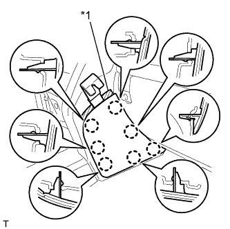
Text in Illustration *1 Protective Tape
-
Put protective tape around the No. 1 instrument panel finish panel cushion.
-
Using a moulding remover, detach the 7 claws and remove the No. 1 instrument panel finish panel cushion.
-
-
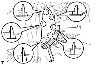
REMOVE LOWER INSTRUMENT PANEL PAD SUB-ASSEMBLY RH
-
Remove the clip and screw.
-
Detach the 7 claws and remove the lower instrument panel pad sub-assembly.
-
-
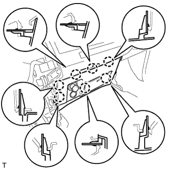
REMOVE LOWER CENTER INSTRUMENT CLUSTER FINISH PANEL SUB-ASSEMBLY
-
Detach the 7 claws.
-
Disconnect the connectors and remove the lower center instrument cluster finish panel sub-assembly.
-
-
REMOVE INSTRUMENT SIDE PANEL LH
Text in Illustration *1 Protective Tape
-
Place protective tape as shown in the illustration.
-
Using a moulding remover, detach the 6 claws and remove the instrument side panel.
-
-
REMOVE NO. 1 INSTRUMENT CLUSTER FINISH PANEL GARNISH
Text in Illustration *1 Protective Tape
-
Place protective tape as shown in the illustration.
-
Using a moulding remover, detach the 3 claws and remove the No. 1 instrument cluster finish panel garnish.
-
-
REMOVE NO. 2 INSTRUMENT CLUSTER FINISH PANEL GARNISH
-
Place protective tape as shown in the illustration.
-
Using a moulding remover, detach the 2 claws and remove the No. 2 instrument cluster finish panel garnish.
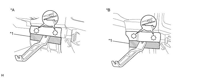
Text in Illustration *A w/ Entry and Start System *B w/o Entry and Start System *1 Protective Tape - -
-
-
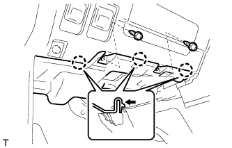
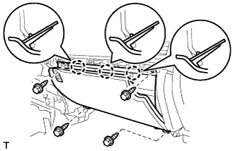
REMOVE NO. 1 INSTRUMENT PANEL UNDER COVER SUB-ASSEMBLY (w/ Floor Under Cover)
-
Remove the 2 screws.
-
Detach the 3 claws.
-
Disconnect the connectors and remove the No. 1 instrument panel under cover.
-
-
REMOVE FRONT DOOR SCUFF PLATE LH
-
REMOVE COWL SIDE TRIM BOARD LH

-
Remove the cap nut.
-
Detach the 2 clips and remove the cowl side trim board.
-
-
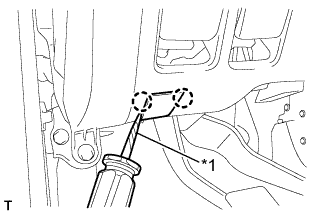
REMOVE LOWER NO. 1 INSTRUMENT PANEL FINISH PANEL
-
Using a screwdriver, detach the 2 claws and open the hole cover.
Tech Tips
Tape the screwdriver tip before use.
Text in Illustration *1 Protective Tape -
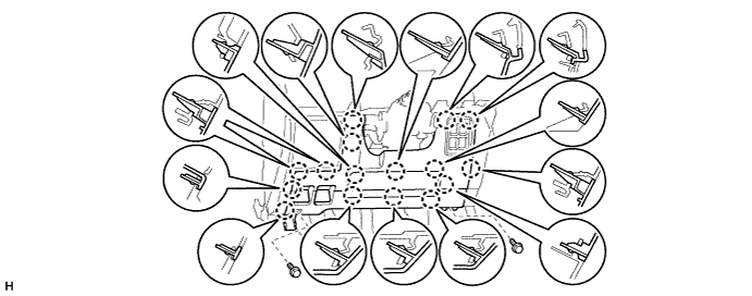
w/ Driver Side Knee Airbag:
-
Remove the 2 bolts.
-
Detach the 16 claws.
-
-
w/o Driver Side Knee Airbag:
-
Remove the 2 bolts.
-
Detach the 9 claws.
-
-
for Automatic Air Conditioning System:
-
Detach the 2 claws and remove the room temperature sensor.
-
-
Detach the 2 claws and disconnect the 2 control cables.
-
Disconnect the connectors and remove the lower No. 1 instrument panel finish panel.
-
-
REMOVE NO. 1 SWITCH HOLE BASE
-
Detach the 4 claws.
-
Disconnect the connectors and remove the No. 1 switch hole cover.
-
-
REMOVE DRIVER SIDE KNEE AIRBAG ASSEMBLY (w/ Driver Side Knee Airbag)
-
Remove the 5 bolts and driver side knee airbag.
-
Disconnect the connector.
Note
When handling the airbag connector, take care not to damage the airbag wire harness.
-
-
REMOVE LOWER INSTRUMENT PANEL SUB-ASSEMBLY (w/o Driver Side Knee Airbag)
-
Detach the 2 claws and disconnect the DLC3.
-
Remove the 5 bolts and lower instrument panel.
-
-
REMOVE INSTRUMENT SIDE PANEL RH (w/o Airbag Cut Off Switch)
Text in Illustration *1 Protective Tape
-
Place protective tape as shown in the illustration.
-
Using a moulding remover, detach the 6 claws and remove the instrument side panel.
-
-
REMOVE INSTRUMENT SIDE PANEL RH (w/ Airbag Cut Off Switch)
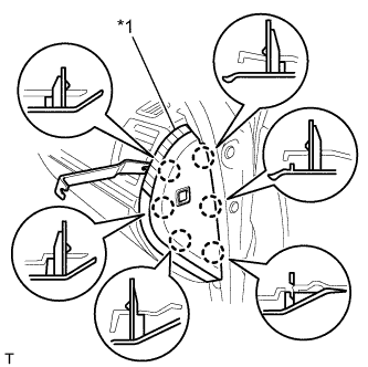
Text in Illustration *1 Protective Tape
-
Place protective tape as shown in the illustration.
-
Using a moulding remover, detach the 6 claws.
-
Disconnect the connector and remove the instrument side panel.
-
-
REMOVE FRONT DOOR SCUFF PLATE RH
-
REMOVE NO. 2 INSTRUMENT PANEL UNDER COVER SUB-ASSEMBLY (w/ Floor Under Cover)
-
Detach the 4 claws and remove the No. 2 instrument panel under cover.
-
-
REMOVE COWL SIDE TRIM BOARD RH
-
Remove the cap nut.
-
Detach the 2 clips and remove the cowl side trim board.
-
-
REMOVE FRONT PASSENGER SIDE KNEE AIRBAG ASSEMBLY (w/ Passenger Side Knee Airbag)
-
Remove the 4 bolts.
-
Detach the 4 claws and remove the front passenger side knee airbag.
-
Disconnect the connector.
Note
When handling the airbag connector, take care not to damage the airbag wire harness.
-
-
REMOVE LOWER INSTRUMENT PANEL (w/o Passenger Side Knee Airbag)
-
Remove the 2 bolts.
-
Detach the 4 claws and remove the lower instrument panel.
-
-
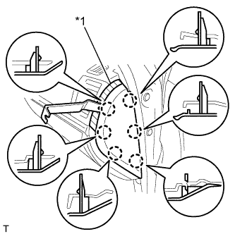
REMOVE NO. 3 INSTRUMENT CLUSTER FINISH PANEL GARNISH
Text in Illustration *1 Protective Tape
-
Place protective tape as shown in the illustration.
-
Using a moulding remover, detach the 6 claws and remove the No. 3 instrument cluster finish panel garnish.
-
-
REMOVE INSTRUMENT PANEL BOX DOOR KNOB
-
Using a moulding remover, detach the 2 claws and remove the instrument panel box door knob.
-
-
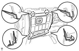
REMOVE LOWER NO. 2 INSTRUMENT PANEL FINISH PANEL
-
Remove the 4 bolts.
-
Detach the 3 claws.
-
Disconnect the connector and remove the lower No. 2 instrument panel finish panel.
-
-
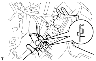
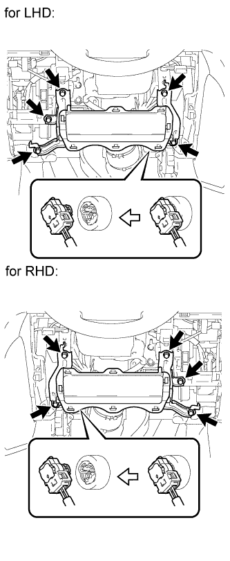
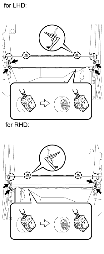
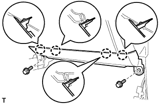
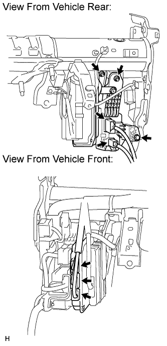
REMOVE STEERING CONTROL ECU WITH JUNCTION BLOCK (for LHD)
-
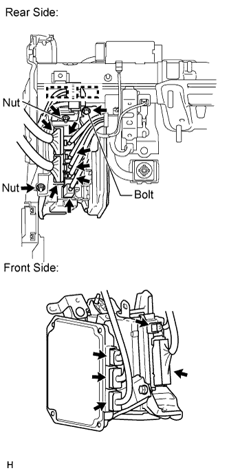
Vehicle rear side:
-
Disconnect the 7 connectors.
-
Detach the 2 clamps.
-
Remove the bolt and 2 nuts.
-
-
Vehicle front side:
-
Disconnect the 5 connectors.
-
-
Remove the steering control ECU with junction block from the vehicle.
-
-
REMOVE STEERING CONTROL ECU WITH JUNCTION BLOCK (for RHD)
-
Vehicle rear side:
-
Disconnect the 2 connectors.
-
Remove the bolt and 2 nuts.
-
-
Vehicle front side:
-
Disconnect the connector.
-
-
Remove the steering control ECU with junction block from the vehicle.
-
-
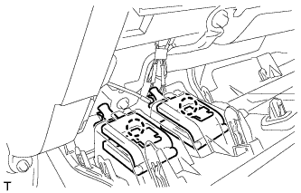
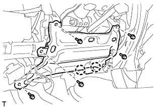
REMOVE ACCELERATION SENSOR (for Driver Side)
-
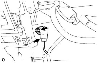
Disconnect the connector.
-
Remove the bolt and sensor.
Tech Tips
Use the same procedures for LHD and RHD vehicles.
-
-
REMOVE ACCELERATION SENSOR (for Front Passenger Side)
-
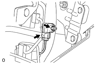
Disconnect the connector.
-
Remove the bolt and sensor.
Tech Tips
Use the same procedures for LHD and RHD vehicles.
-