ACTIVE HEIGHT CONTROL SUSPENSION, Diagnostic DTC:C1782

| DTC Code | DTC Name |
|---|---|
| C1782 | Power Source Voltage Malfunction |
DESCRIPTION
| DTC Code | Detection Condition | Trouble Area |
|---|---|---|
| C1782 | While the engine switch is on (IG), voltage at terminal IG, BAT and/or BAT2 is 10 V or less, or 16 V or more for 0.5 seconds. |
|
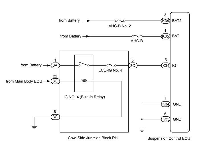
WIRING DIAGRAM
INSPECTION PROCEDURE
Note
-
Even if DTC C1781 is stored at the same time, perform the inspection for DTC C1782 first.
-
Before performing troubleshooting, inspect the connectors of related circuits.
-
If the suspension control ECU or height control sensor is replaced, the vehicle height offset calibration must be performed Click here.
PROCEDURE
-
READ VALUE USING INTELLIGENT TESTER (IG VOLTAGE)
-
Connect the intelligent tester to the DLC3.
-
Turn the engine switch on (IG) and the tester on.
-
Read the "IG Power Source Voltage" item in the Data List.
AHC Tester Display Measurement Item/Range Normal Condition Diagnostic Note IG Power Source Voltage Power supply voltage /
min.: 0 V
max.: 255 V
Engine switch on (IG): 11 to 14 V - OK 11 to 14 V
NG 
CHECK HARNESS AND CONNECTOR (BATTERY - ECU AND BODY GROUND) Click here
OK 
-
-
RECONFIRM DTC OUTPUT
-
Clear the DTCs Click here.
-
Check for DTCs.
Result Result Proceed to DTC is output A DTC is not output B
B 
USE SIMULATION METHOD TO CHECK Click here
A
-
-
READ VALUE USING INTELLIGENT TESTER (+B POWER SOURCE VOLTAGE, +B2 POWER SOURCE VOLTAGE)
-
Connect the intelligent tester to the DLC3.
-
Turn the engine switch on (IG) and the tester on.
-
Read the "+B Power Source Voltage" and "+B2 Power Source Voltage" items in the Data List.
AHC Tester Display Measurement Item/Range Normal Condition Diagnostic Note +B Power Source Voltage Power supply for absorber control actuator /
min.: 0 V
max.: 255 V
Engine switch on (IG): 11 to 14 V - +B2 Power Source Voltage Power supply for No. 1 height control valve and front suspension control valve /
min.: 0 V
max.: 255 V
Engine switch on (IG): 11 to 14 V - OK 11 to 14 V
NG
INSPECT FUSE (AHC-B, AHC-B NO. 2) Click here
OK 
REPLACE SUSPENSION CONTROL ECU Click here
-
-
INSPECT FUSE (AHC-B, AHC-B NO. 2)
-
Remove the AHC-B and AHC-B No. 2 fuses from the cowl side junction block RH.
-
Measure the resistance according to the value(s) in the table below.
Standard Resistance Tester Connection Condition Specified Condition AHC-B fuse Always Below 1 Ω AHC-B No. 2 fuse Always Below 1 Ω
NG
CHECK FOR SHORT IN ALL HARNESSES AND CONNECTORS CONNECTED TO FUSE AND REPLACE FUSE
OK
-
-
CHECK HARNESS AND CONNECTOR (BATTERY - SUSPENSION CONTROL ECU)
-
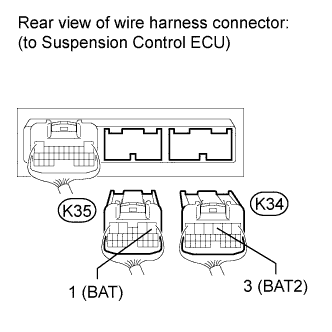
Disconnect the K34 and K35 ECU connectors.
-
Measure the voltage according to the value(s) in the table below.
Standard Voltage Tester Connection Switch Condition Specified Condition K34-3 (BAT2) - Body ground Engine switch on (IG) 11 to 14 V K35-1 (BAT) - Body ground Engine switch on (IG) 11 to 14 V
NG
REPAIR OR REPLACE HARNESS OR CONNECTOR
OK
REPLACE SUSPENSION CONTROL ECU Click here
-
-
CHECK HARNESS AND CONNECTOR (BATTERY - ECU AND BODY GROUND)
-
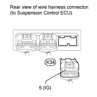
Disconnect the K34 ECU connector.
-
Measure the voltage according to the value(s) in the table below.
Standard Voltage Tester Connection Switch Condition Specified Condition K34-5 (IG) - Body ground Engine switch on (IG) 11 to 14 V Result Result Proceed to OK A NG (1UR-FE) B NG (1VD-FTV) C
B
BATTERY VOLTAGE IS LOW OR CHARGING SYSTEM HAS MALFUNCTION
C
BATTERY VOLTAGE IS LOW OR CHARGING SYSTEM HAS MALFUNCTION
A
REPLACE SUSPENSION CONTROL ECU Click here
-