MANUAL TRANSMISSION ASSEMBLY INSTALLATION

-
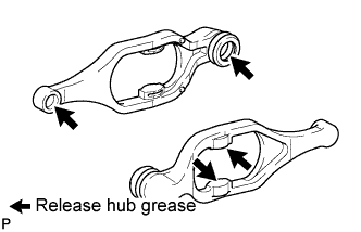
INSTALL CLUTCH RELEASE FORK SUB-ASSEMBLY
-
Apply release hub grease to the release fork, release bearing, push rod contact point and pivot points shown in the illustration.
Grease Toyota Genuine Release Hub Grease or equivalent -
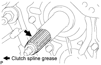
Apply clutch spline grease to the input shaft spline.
Grease Toyota Genuine Clutch Spline Grease or equivalent -
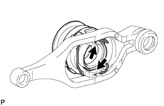
Install the release bearing to the clutch release fork with the clip.
-
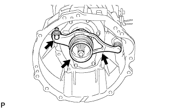
Install the release fork support to the transmission unit.
- Torque:
- 47 N*m { 480 kgf*cm, 35 ft.*lbf }
-
Install the clutch release fork with the clutch release bearing to the transmission unit.
Tech Tips
After installation, move the fork back and forth to check that the release bearing slides smoothly.
-
-
INSTALL TRANSFER ASSEMBLY
-
Install the transfer with the 8 bolts.
- Torque:
- 40 N*m { 408 kgf*cm, 30 ft.*lbf }
Note
Take care not to damage the adaptor oil seal with the transfer input shaft spline.
-
-
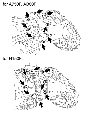
INSTALL MANUAL TRANSMISSION WITH TRANSFER (for 1GR-FE)
Note
Check that the 2 straight pins are attached to the engine side.
-
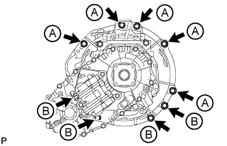
Install the manual transmission with transfer with the 9 bolts.
- Torque:
- for bolt A
- 72 N*m { 730 kgf*cm, 53 ft.*lbf }
- for bolt B
- 37 N*m { 380 kgf*cm, 28 ft.*lbf }
Bolt Length Item Length Bolt A 50 mm (1.97 in.) Bolt B 45 mm (1.77 in.)
-
-
INSTALL MANUAL TRANSMISSION WITH TRANSFER (for 1VD-FTV)
Note
Check that the 2 straight pins are attached to the engine side.
-
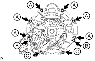
Install the manual transmission with transfer with the 10 bolts.
- Torque:
- for bolt A and B
- 72 N*m { 730 kgf*cm, 53 ft.*lbf }
- for bolt C
- 39 N*m { 400 kgf*cm, 29 ft.*lbf }
Bolt Length Item Length Bolt A 45 mm (1.77 in.) Bolt B 50 mm (1.97 in.) Bolt C 70 mm (2.76 in.)
-
-
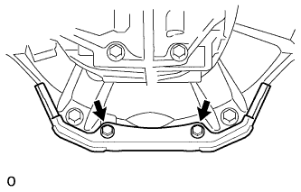
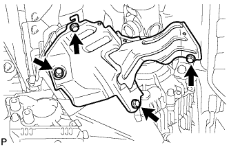
INSTALL OIL PAN COVER (for 1VD-FTV)
-
Install the oil pan cover with the 2 bolts.
- Torque:
- 21 N*m { 214 kgf*cm, 15 ft.*lbf }
-
-
INSTALL CLUTCH RELEASE CYLINDER TO FLEXIBLE HOSE TUBE
-
Install the flexible hose tube with the 3 bolts.
- Torque:
- 20 N*m { 204 kgf*cm, 15 ft.*lbf }
-
-
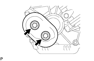
INSTALL CLUTCH RELEASE CYLINDER ASSEMBLY
-
Install the clutch release cylinder with the 2 bolts.
- Torque:
- 12 N*m { 120 kgf*cm, 9 ft.*lbf }
-
-
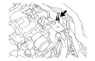
INSTALL CLUTCH ACCUMULATOR ASSEMBLY
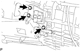
-
Install the clutch accumulator with the 3 bolts.
- Torque:
- 12 N*m { 120 kgf*cm, 9 ft.*lbf }
-
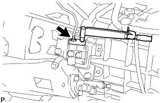
Using a union nut wrench, connect the flexible hose tube.
- Torque:
- 15 N*m { 155 kgf*cm, 11 ft.*lbf }
Note
Use the formula to calculate special torque values for situations where a union nut wrench is combined with a torque wrench Click here.
-
-
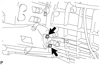
INSTALL CLUTCH RELEASE CYLINDER TO ACCUMULATOR TUBE
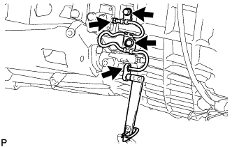
-
Using a union nut wrench, connect the tube to the clutch accumulator and release cylinder.
- Torque:
- 16 N*m { 158 kgf*cm, 11 ft.*lbf }
Note
Use the formula to calculate special torque values for situations where a union nut wrench is combined with a torque wrench Click here.
-
Install the tube with the 2 bolts.
- Torque:
- 12 N*m { 120 kgf*cm, 9 ft.*lbf }
-
-
INSTALL NO. 1 CLUTCH HOUSING COVER
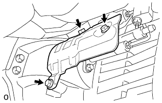
-
Install the housing cover with the 3 bolts.
- Torque:
- 12 N*m { 120 kgf*cm, 9 ft.*lbf }
-
-
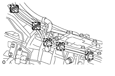
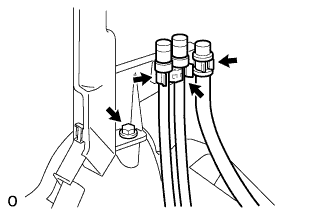
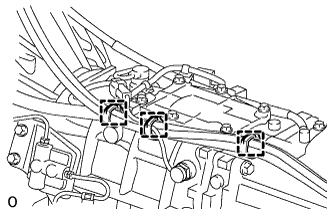
CONNECT WIRE HARNESS (for 1GR-FE)

-
Connect the 6 clamps.
-
Connect the back-up light switch connector.
-
Install the 2 bolts.
- Torque:
- for LH side
- 60 N*m { 612 kgf*cm, 44 ft.*lbf }
- for RH side
- 29 N*m { 296 kgf*cm, 21 ft.*lbf }
-
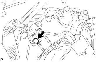
Connect the ground cable with the bolt.
- Torque:
- 8.0 N*m { 82 kgf*cm, 71 in.*lbf }
-
Connect the 2 connectors and 3 clamps.
-
-
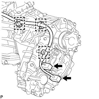
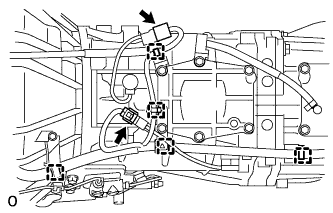
CONNECT WIRE HARNESS (for 1VD-FTV)
-
Connect the 5 clamps.
-
Connect the back-up light switch connector.
-
Connect the shift position switch connector.
-
Connect the ground cable with the bolt.
- Torque:
- 8.0 N*m { 82 kgf*cm, 71 in.*lbf }
-
Connect the 2 connectors and 3 clamps.
-
-
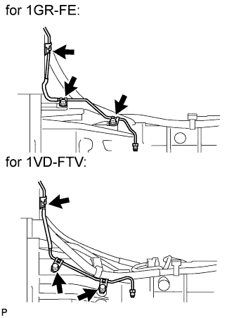
INSTALL TRANSFER BREATHER HOSE SUB-ASSEMBLY (for 1GR-FE)
-
Connect the 2 breather hoses to the bracket.
-
Connect the 5 clamps.
-
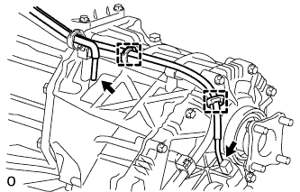
Connect the breather hose to the transfer and actuator, and attach the 2 clamps.
-
-
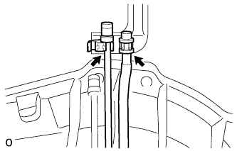
INSTALL TRANSFER BREATHER HOSE SUB-ASSEMBLY (for 1VD-FTV)
-
Install the bracket with the bolt.
-
Connect the 3 breather hoses to the bracket.
-
Connect the 3 clamps.
-
Connect the breather hose to the transfer and actuator, and attach the 2 clamps.
-
-
INSTALL REAR NO. 1 ENGINE MOUNTING INSULATOR
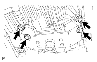
-
Install the engine mounting insulator to the transmission with the 4 bolts.
- Torque:
- 59 N*m { 602 kgf*cm, 44 ft.*lbf }
-
-
INSTALL NO. 2 FRAME CROSSMEMBER SUB-ASSEMBLY
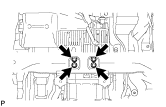
-
Install the frame crossmember to the rear engine mounting insulator with the 4 bolts.
- Torque:
- 37 N*m { 377 kgf*cm, 27 ft.*lbf }
-
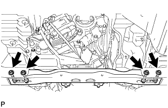
Install the frame crossmember to the vehicle body with the 4 bolts, 4 washers and 4 nuts.
- Torque:
- 110 N*m { 1,122 kgf*cm, 81 ft.*lbf }
-
-
INSTALL STARTER ASSEMBLY (for 1GR-FE)
-
INSTALL NO. 2 MANIFOLD STAY (for 1GR-FE)
-
Install the No. 2 manifold stay with the 3 bolts.
- Torque:
- 40 N*m { 408 kgf*cm, 30 ft.*lbf }
-
-
INSTALL MANIFOLD STAY (for 1GR-FE)
-
Install the manifold stay with the 3 bolts.
- Torque:
- 40 N*m { 408 kgf*cm, 30 ft.*lbf }
-
-
INSTALL EXHAUST PIPE (for 1GR-FE)
-
INSTALL EXHAUST PIPE (for 1VD-FTV)
w/o DPF: Click here
w/ DPF: Click here
-
INSTALL FRONT PROPELLER SHAFT ASSEMBLY
-
INSTALL PROPELLER SHAFT ASSEMBLY
-
ADD MANUAL TRANSMISSION OIL
-
INSPECT TRANSMISSION OIL
-
Park the vehicle in a level place.
-
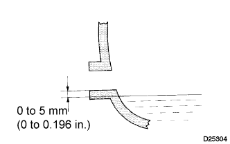
Check that the oil level is within 5 mm (0.196 in.) of the lowest point of the transmission filler plug opening.
Note
-
Problems may occur when the oil level is too high or low.
-
After replacing the oil, drive the vehicle and check the oil level again.
-
-
Inspect for oil leaks when the oil level is low.
-
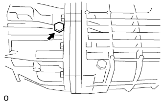
Install a new gasket and the filler plug.
- Torque:
- 37 N*m { 380 kgf*cm, 27 ft.*lbf }
-
-
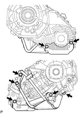
INSTALL LOWER TRANSFER CASE PROTECTOR
-
Install the lower transfer case protector with the 7 bolts.
- Torque:
- 14 N*m { 139 kgf*cm, 10 ft.*lbf }
-
-
INSTALL TRANSFER DYNAMIC DAMPER (for 1VD-FTV)
-
Install the transfer dynamic damper with the 2 bolts.
- Torque:
- 12 N*m { 122 kgf*cm, 9 ft.*lbf }
-
-
INSTALL TRANSFER HEAT INSULATOR
-
Install the insulator with the 4 bolts.
- Torque:
- 30 N*m { 306 kgf*cm, 22 ft.*lbf }
-
-
INSTALL TUBE CONNECTOR TO FLEXIBLE HOSE TUBE (for 1VD-FTV)
-
Temporarily install the flare nut of the tube connector to flexible hose tube to the clutch tube to release cylinder 2 way by hand.
-
Temporarily install the tube connector to flexible hose tube with the 2 bolts.
-
Tighten the bolt labeled A.
- Torque:
- 20 N*m { 204 kgf*cm, 15 ft.*lbf }
Note
Tighten the bolt labeled B after installing the clutch hose.
-
-
INSTALL AIR TUBE SUB-ASSEMBLY LH (for 1VD-FTV)
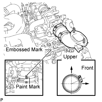
-
Install the air tube to the throttle body.
-
Align the embossed mark of the throttle body with the paint mark of the No. 4 air hose.
-
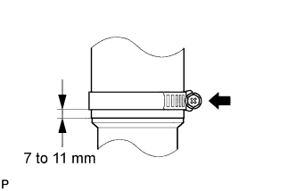
Tighten the hose clamp so that it is 7 to 11 mm (0.276 to 0.433 in.) from the end of the hose as shown in the illustration.
- Torque:
- 6.3 N*m { 64 kgf*cm, 56 in.*lbf }
-
-
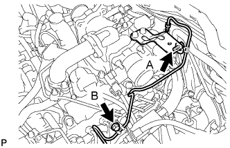
INSTALL CLUTCH HOSE (for 1VD-FTV)
-
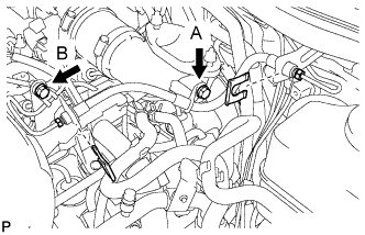
Connect the clutch hose to the air tube with the bolt labeled A.
-
Temporarily install the clutch hose to the clutch master cylinder tube to flexible hose tube and tube connector to flexible hose tube, and fix it in place with the 2 clips.
- Torque:
- 20 N*m { 204 kgf*cm, 15 ft.*lbf }
-
Tighten the bolt labeled B.
- Torque:
- 20 N*m { 204 kgf*cm, 15 ft.*lbf }
-
Tighten the flexible hose tube.
Note
-
Do not bend or damage the flexible hose tube.
-
Do not allow any foreign matter such as dirt and dust to enter the flexible hose tube from the connecting points.
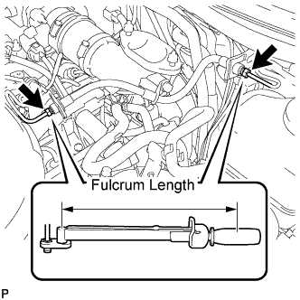
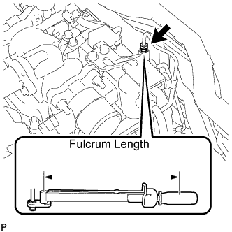
Tech Tips
-
Use a torque wrench with a fulcrum length of 30 cm (11.8 in.). If using a torque wrench with a length that is not 30 cm (11.8 in.), calculate the torque specification for the torque wrench and SST based on the "without SST" torque specification Click here.
-
Make sure union nut wrench and the wrench are connected in a straight line.
-
Using a 10 mm union nut wrench, tighten the 2 flare nuts of the flexible hose tube.
- Torque:
- without union nut wrench
- 15 N*m { 154 kgf*cm, 11 ft.*lbf }
- with union nut wrench
- 14 N*m { 141 kgf*cm, 10 ft.*lbf }
-
Using a 10 mm union nut wrench, tighten the flare nut of the flexible hose tube.
- Torque:
- without union nut wrench
- 15 N*m { 154 kgf*cm, 11 ft.*lbf }
- with union nut wrench
- 14 N*m { 141 kgf*cm, 10 ft.*lbf }
-
-
-
INSTALL NO. 2 COOL AIR INLET (w/o Intercooler)
-
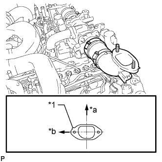
Text in Illustration *1 Protrusion *a Front *b LH Side Install a new gasket to the air tube LH.
Tech Tips
Install the gasket with the protrusion facing as shown in the illustration.
-
Install the No. 2 cool air inlet with the 3 nuts and bolt.
- Torque:
- 21 N*m { 214 kgf*cm, 15 ft.*lbf }
-
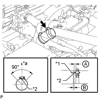
Text in Illustration *1 Protrusion *2 Paint Mark *a Top Connect the No. 2 air hose to the No. 2 cool air inlet.
-
Tighten the No. 2 air hose clamp.
- Torque:
- 6.3 N*m { 64 kgf*cm, 56 in.*lbf }
Tech Tips
-
Align the paint mark of the air hose with the protrusion and push on the air hose so that distance B is 0 to 3 mm (0 to 0.118 in.).
-
Position the clamp so that distance A is 2 to 6 mm (0.0787 to 0.236 in.).
-
Make sure the direction of the hose clamp is as shown in the illustration.
-
-
INSTALL INTERCOOLER ASSEMBLY (w/ Intercooler)
-
INSTALL NO. 1 ENGINE COVER SUB-ASSEMBLY
-
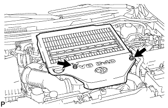
Install the engine cover with the 2 nuts.
- Torque:
- 8.0 N*m { 82 kgf*cm, 71 in.*lbf }
-
-
INSTALL FLOOR SHIFT LEVER ASSEMBLY
-
Apply MP grease to the tip of the shift lever.
-
Cover the shift lever cap with a cloth.
-
Press down on the shift lever cap and rotate it clockwise to install it.
-
-
INSTALL SHIFT LEVER BOOT ASSEMBLY
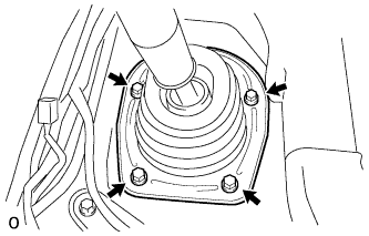
-
Install the shift lever retainer and shift lever boot with the 4 screws.
-
-
INSTALL UPPER CONSOLE PANEL SUB-ASSEMBLY
w/o Console Box Lid Click here
w/ Cool Box Click here
w/o Cool Box Click here
-
FILL RESERVOIR WITH BRAKE FLUID
-
Fill the reservoir with brake fluid.
Brake Fluid SAE J1703 or FMVSS No. 116 DOT 3
-
-
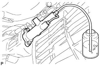
BLEED CLUTCH LINE
-
Remove the release cylinder bleeder plug cap.
-
Connect a vinyl tube to the bleeder plug.
-
Depress the clutch pedal several times, and then loosen the bleeder plug while the pedal is depressed.
-
When fluid no longer comes out, tighten the bleeder plug, and then release the clutch pedal.
-
Repeat the previous 2 steps until all the air in the fluid is completely bled.
-
Tighten the bleeder plug.
- Torque:
- 11 N*m { 110 kgf*cm, 8 ft.*lbf }
-
Install the bleeder plug cap.
-
Check that all the air has been bled from the clutch line.
-
-
CHECK FLUID LEVEL IN RESERVOIR
-
Check the fluid level.
If the brake fluid level is low, check for leaks and inspect the disc brake pad. If necessary, refill the reservoir with brake fluid after repair or replacement.
Brake fluid SAE J1703 or FMVSS No. 116 DOT 3
-
-
INSPECT FOR CLUTCH FLUID LEAK
-
CONNECT CABLE TO NEGATIVE BATTERY TERMINAL
Note
When disconnecting the cable, some systems need to be initialized after the cable is reconnected Click here.