MANUAL TRANSMISSION ASSEMBLY REMOVAL

-
PRECAUTION
Note
After turning the ignition switch off, waiting time may be required before disconnecting the cable from the battery terminal. Therefore, make sure to read the disconnecting the cable from the battery terminal notice before proceeding with work Click here
-
DISCONNECT CABLE FROM NEGATIVE BATTERY TERMINAL
Note
When disconnecting the cable, some systems need to be initialized after the cable is reconnected Click here.
-
REMOVE UPPER CONSOLE PANEL SUB-ASSEMBLY
w/o Console Box Lid Click here
w/ Cool Box Click here
w/o Cool Box Click here
-
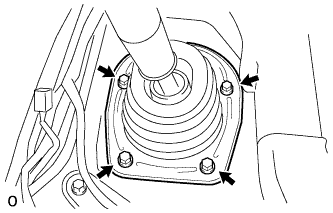
REMOVE SHIFT LEVER BOOT ASSEMBLY
-
Remove the 4 screws, shift lever retainer and shift lever boot.
-
-
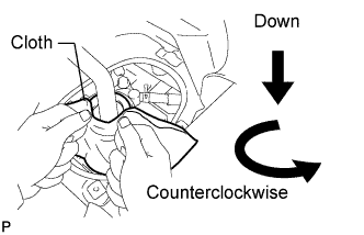
REMOVE FLOOR SHIFT LEVER ASSEMBLY
-
Cover the shift lever cap with a cloth.
-
Press down on the shift lever cap and rotate it counterclockwise to remove it.
-
Pull out the shift lever.
-
-
REMOVE NO. 1 ENGINE COVER SUB-ASSEMBLY (w/ Intercooler)
-
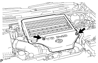
Remove the 2 nuts and No. 1 engine cover.
-
-
REMOVE INTERCOOLER ASSEMBLY (w/ Intercooler)
-
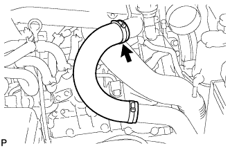
Loosen the No. 1 air hose clamp.
-
Loosen the No. 2 air hose clamp.
-
Disconnect the turbo pressure sensor connector, intake air temperature sensor connector and vacuum hose.
-
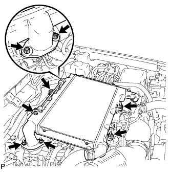
Remove the 6 nuts, 2 bolts and intercooler.
-
Remove the 2 gaskets from the air tube LH and RH.
-
-
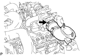
REMOVE NO. 2 COOL AIR INLET (w/o Intercooler)
-
Loosen the No. 2 air hose clamp.
-
Remove the 3 nuts, bolt and No. 2 cool air inlet.
-
Remove the gasket from the air tube LH.
-
-
DRAIN CLUTCH FLUID
-
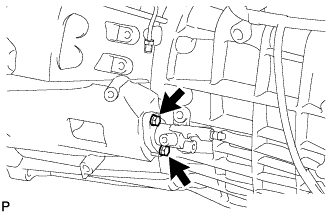
REMOVE CLUTCH HOSE (for 1VD-FTV)
-
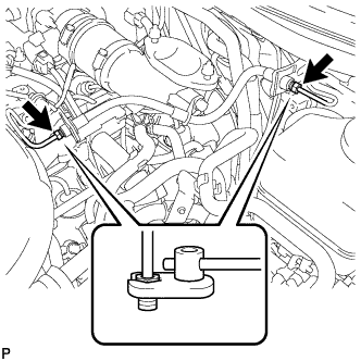
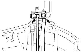
Disconnect the 2 flexible hose tubes from the clutch hose with a 10 mm union nut wrench while holding the flexible hose with a wrench.
Note
-
Do not bend or damage the flexible hose tubes.
-
Do not allow any foreign matter such as dirt and dust to enter the flexible hose tubes from the connecting point.
-
-
Remove the 2 clips.
-
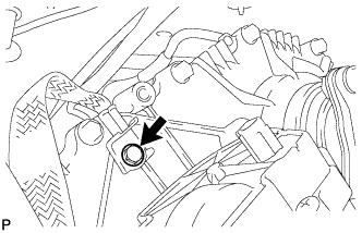
Remove the bolt and clutch hose.
-
-
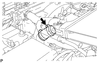
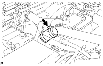
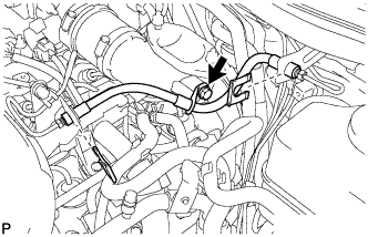
REMOVE AIR TUBE SUB-ASSEMBLY LH (for 1VD-FTV)
-
Loosen the hose clamp.
-
Remove the air tube from the throttle body.
-
-
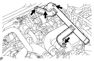
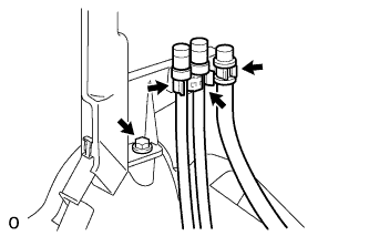
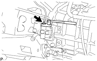
REMOVE TUBE CONNECTOR TO FLEXIBLE HOSE TUBE (for 1VD-FTV)
-
Using a 10 mm union nut wrench, disconnect the tube connector to flexible hose tube from the clutch tube to release cylinder 2 way.
Note
-
Do not bend or damage the flexible hose tube.
-
Do not allow any foreign matter such as dirt and dust to enter the flexible hose tube from the connecting point.
-
-
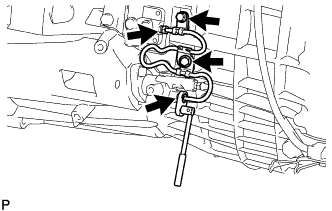
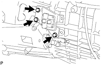
Remove the 2 bolts and tube connector to flexible hose tube.
-
-
REMOVE TRANSFER HEAT INSULATOR
-
Remove the 4 bolts and insulator.
-
-
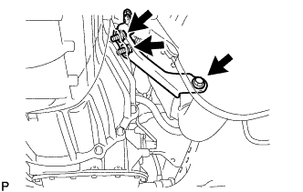
REMOVE TRANSFER DYNAMIC DAMPER (for 1VD-FTV)
-
Remove the 2 bolts and transfer dynamic damper.
-
-
REMOVE LOWER TRANSFER CASE PROTECTOR
-
Remove the 7 bolts and lower transfer case protector.
-
-
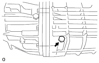
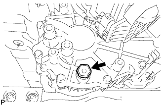
DRAIN MANUAL TRANSMISSION OIL
-
Remove the drain plug and gasket and then drain the manual transmission oil.
-
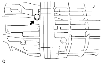
Remove the filler plug and gasket.
-
Install a new gasket and the drain plug.
- Torque:
- 37 N*m { 380 kgf*cm, 27 ft.*lbf }
-
-
DRAIN TRANSFER OIL
-
except 1GR-FE:
Remove the 2 bolts and transfer dynamic damper.
-
Remove the 4 bolts and transfer heat insulator.
-
Remove the 7 bolts and lower transfer case protector.
-
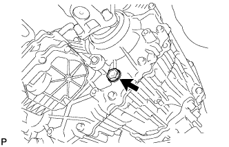
Remove the filler plug and gasket.
-
Remove the drain plug and gasket, and drain the transfer oil.
-
-
REMOVE PROPELLER SHAFT ASSEMBLY
-
REMOVE FRONT PROPELLER SHAFT ASSEMBLY
-
REMOVE EXHAUST PIPE (for 1GR-FE)
-
REMOVE EXHAUST PIPE (for 1VD-FTV)
w/o DPF: Click here
w/ DPF: Click here
-
REMOVE MANIFOLD STAY (for 1GR-FE)
-
Remove the 3 bolts and manifold stay.
-
-
REMOVE NO. 2 MANIFOLD STAY (for 1GR-FE)
-
Remove the 3 bolts and No. 2 manifold stay.
-
-
REMOVE STARTER ASSEMBLY (for 1GR-FE)
-
REMOVE NO. 2 FRAME CROSSMEMBER SUB-ASSEMBLY
-
Support the transmission with a transmission jack. Lift the transmission slightly from the crossmember.
-
Remove the 4 bolts of the rear engine mounting insulator.
-
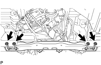
Remove the 4 bolts, 4 nuts, 4 washers and frame crossmember.
-
-
REMOVE REAR NO. 1 ENGINE MOUNTING INSULATOR
-
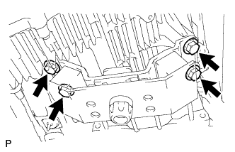
Remove the 4 bolts and engine mounting insulator.
-
-
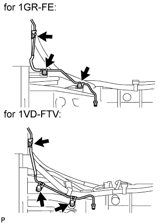
REMOVE TRANSFER BREATHER HOSE SUB-ASSEMBLY (for 1GR-FE)
-
Disconnect the breather hose from the transfer and actuator, and disconnect the 2 clamps.
-
Disconnect the 5 clamps.
-
Disconnect the 2 breather hoses from the bracket.
-
-
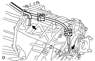
REMOVE TRANSFER BREATHER HOSE SUB-ASSEMBLY (for 1VD-FTV)
-
Disconnect the breather hose from the transfer and actuator, and disconnect the 2 clamps.
-
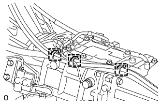
Disconnect the 3 clamps.
-
Disconnect the 3 breather hoses from the bracket.
-
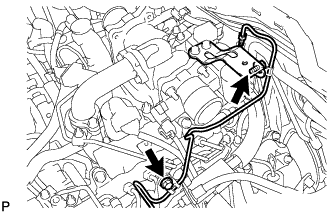
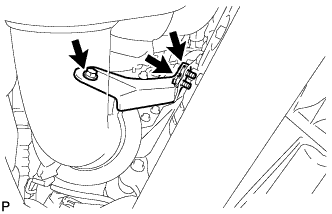
Remove the bolt and disconnect the bracket from the transmission.
-
-
DISCONNECT WIRE HARNESS (for 1GR-FE)
-
Disconnect the 2 connectors and 3 clamps.
-
Remove the bolt and disconnect the ground cable.
-
Tilt the transmission downward.
Note
Make sure the cooling fan does not contact the fan shroud.
-

Remove the 2 bolts.
-
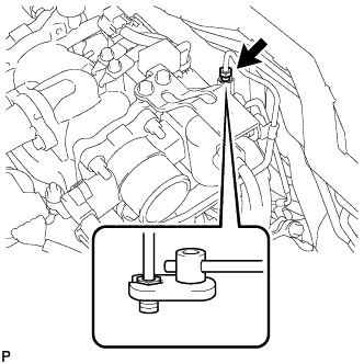
Disconnect the back-up light switch connector.
-
Disconnect the 6 clamps.
-
-
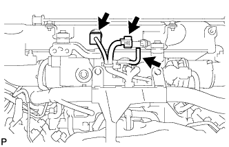
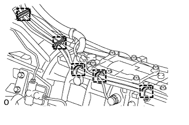
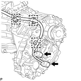
DISCONNECT WIRE HARNESS (for 1VD-FTV)
-
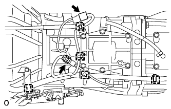
Disconnect the 2 connectors and 3 clamps.
-
Remove the bolt and disconnect the ground cable.
-
Tilt the transmission downward.
Note
Make sure the cooling fan does not contact the fan shroud.
-
Disconnect the shift position switch connector.
-
Disconnect the back-up light switch connector.
-
Disconnect the 5 clamps.
-
-
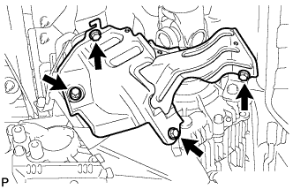
REMOVE NO. 1 CLUTCH HOUSING COVER
-
Remove the 3 bolts and clutch housing cover.
-
-
REMOVE CLUTCH RELEASE CYLINDER TO ACCUMULATOR TUBE
-
Using a union nut wrench, disconnect the tube.
Tech Tips
Use a container to catch the fluid.
-
Remove the 2 bolts and tube.
-
-
REMOVE CLUTCH ACCUMULATOR ASSEMBLY
-
Using a union nut wrench, disconnect the flexible hose tube.
Tech Tips
Use a container to catch the fluid.
-
Remove the 3 bolts and clutch accumulator.
-
-
REMOVE CLUTCH RELEASE CYLINDER ASSEMBLY
-
Remove the 2 bolts and pull out the clutch release cylinder.
-
-
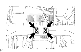
REMOVE CLUTCH RELEASE CYLINDER TO FLEXIBLE HOSE TUBE
-
Remove the 3 bolts and flexible hose tube.
-
-
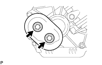
REMOVE OIL PAN COVER (for 1VD-FTV)
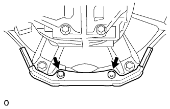
-
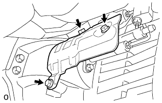
Remove the 2 bolts and oil pan cover.
-
-
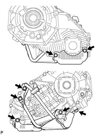
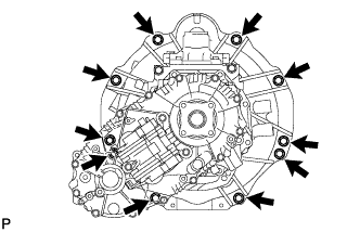
REMOVE MANUAL TRANSMISSION WITH TRANSFER (for 1GR-FE)
-
Remove the 9 bolts and manual transmission with transfer.
-
-
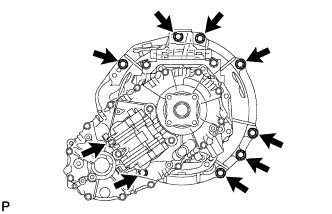
REMOVE MANUAL TRANSMISSION WITH TRANSFER (for 1VD-FTV)
-
Remove the 10 bolts and manual transmission with transfer.
-
-
REMOVE TRANSFER ASSEMBLY
-
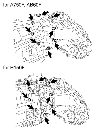
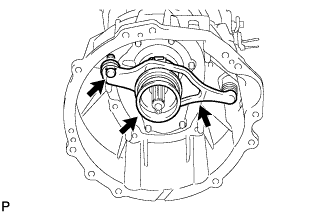
Remove the 8 transfer adaptor rear mounting bolts.
-
Pull the transfer straight up and remove it from the transmission.
Note
Take care not to damage the adaptor oil seal with the transfer input shaft spline.
-
-
REMOVE CLUTCH RELEASE FORK SUB-ASSEMBLY
-
Remove the clutch release fork with the clutch release bearing from the transmission unit.
-
Remove the release fork support from the transmission unit.
-
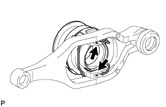
Remove the clip and release bearing from the clutch release fork.
-