AUTOMATIC TRANSMISSION ASSEMBLY (for 1GR-FE) REMOVAL

-
PRECAUTION
Note
After turning the engine switch off, waiting time may be required before disconnecting the cable from the battery terminal. Therefore, make sure to read the disconnecting the cable from the battery terminal notice before proceeding with work Click here.
-
DISCONNECT CABLE FROM NEGATIVE BATTERY TERMINAL
Note
When disconnecting the cable, some systems need to be initialized after the cable is reconnected Click here.
-
REMOVE FRONT FENDER SPLASH SHIELD SUB-ASSEMBLY LH
-
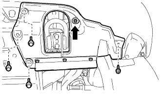
Remove the 3 bolts and screw.
-
Turn the clip indicated by the arrow in the illustration to remove the front fender splash shield sub-assembly LH.
-
-
REMOVE FRONT FENDER SPLASH SHIELD SUB-ASSEMBLY RH
-
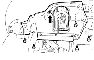
Remove the 3 bolts and 2 screws.
-
Turn the clip indicated by the arrow in the illustration to remove the front fender splash shield sub-assembly RH.
-
-
REMOVE NO. 2 ENGINE UNDER COVER
-
Remove the 2 bolts and No. 2 engine under cover.
-
-
REMOVE NO. 1 ENGINE UNDER COVER
-
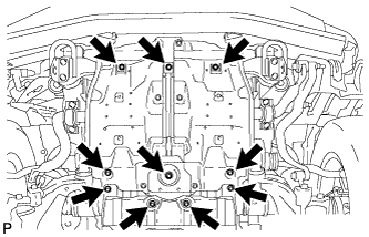
Remove the 10 bolts and No. 1 engine under cover.
-
-
REMOVE FRONT FENDER APRON TRIM PACKING B
-
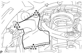
w/ KDSS:
Remove the 3 clips and front fender apron trim packing B.
-
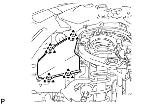
w/o KDSS:
Remove the 4 clips and front fender apron trim packing B.
-
-
REMOVE FRONT FENDER APRON TRIM PACKING D
-
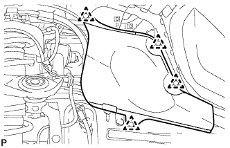
Remove the 4 clips and front fender apron trim packing D.
-
-
REMOVE FRONT FENDER APRON TRIM PACKING A
-
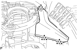
Remove the 3 clips and front fender apron trim packing A.
-
-
REMOVE FRONT FENDER APRON TRIM PACKING C
-
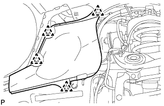
Remove the 4 clips and front fender apron trim packing C.
-
-
DRAIN AUTOMATIC TRANSMISSION FLUID
-
Remove the drain plug and gasket, and drain the ATF.
-
Install a new gasket and the drain plug.
- Torque:
- 20 N*m { 204 kgf*cm, 15 ft.*lbf }
-
-
REMOVE FRONT PROPELLER SHAFT ASSEMBLY
-
REMOVE PROPELLER SHAFT ASSEMBLY
-
REMOVE EXHAUST PIPE
-
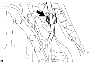
DISCONNECT FLOOR SHIFT GEAR SHIFTING ROD SUB-ASSEMBLY
-
Remove the clip and pin, and disconnect the gear shifting rod from the transmission control shaft lever RH.
-
-
REMOVE STARTER ASSEMBLY
-
REMOVE DRIVE PLATE AND TORQUE CONVERTER CLUTCH SETTING BOLT
-
Remove the flywheel housing side cover.
-
Turn the crankshaft to gain access to the 6 bolts and remove each bolt while holding the crankshaft pulley setting bolt with a wrench.
-
-
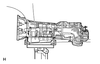
SUPPORT AUTOMATIC TRANSMISSION ASSEMBLY
-
Support the transmission with a transmission jack. Lift the transmission slightly from the crossmember.
-
-
REMOVE NO. 2 FRAME CROSSMEMBER SUB-ASSEMBLY
-
Remove the engine mounting hole cover.
-
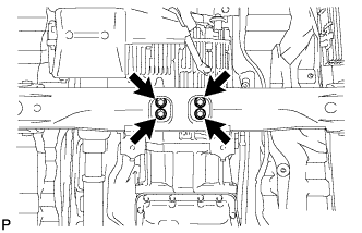
Remove the 4 bolts of the rear engine mounting insulator.
-
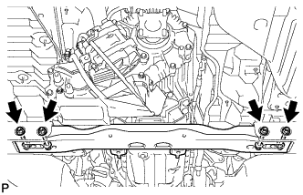
Remove the 4 nuts, 4 bolts and frame crossmember.
-
-
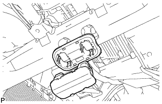
REMOVE REAR NO. 1 ENGINE MOUNTING INSULATOR
-
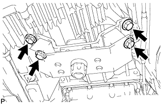
Remove the 4 bolts and rear engine mounting insulator from the transmission.
-
-
DISCONNECT WIRE HARNESS AND CONNECTOR
-
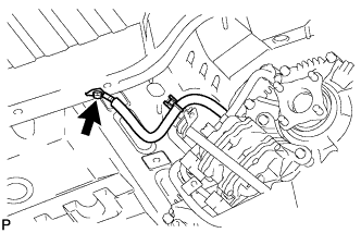
Remove the bolt and disconnect the ground cable.
-
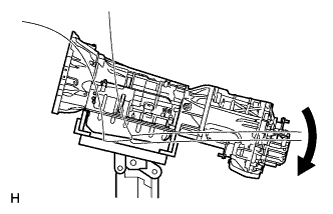
Tilt the transmission downward.
Note
Make sure the cooling fan does not contact the fan shroud.
-
Disconnect the park/neutral position switch connector, transmission wire connector, 2 transmission speed sensor connectors and 2 transfer control side connectors.
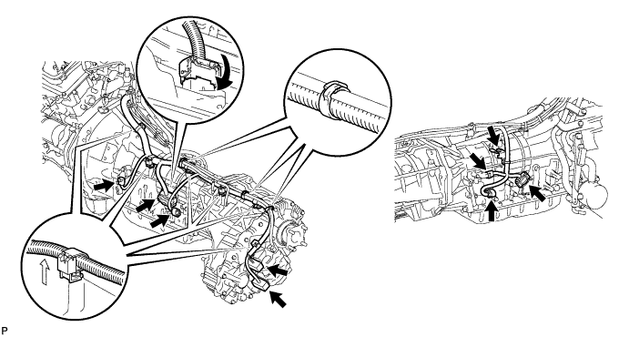
Tech Tips
Detach the claw, press down the lever, and then disconnect the transmission wire connector.
-
Disconnect the 2 connector clamps and 6 harness clamps.
-
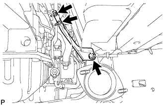
Remove the bolt and disconnect the wire harness.
-
-
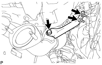
REMOVE MANIFOLD STAY
-
Remove the 3 bolts and stay.
-
-
REMOVE NO. 2 MANIFOLD STAY
-
Remove the 3 bolts and stay.
-
-
DISCONNECT BREATHER PLUG HOSE
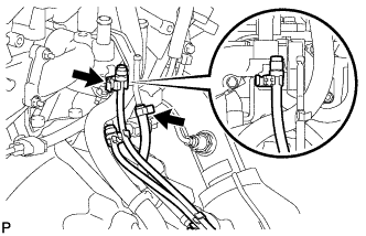
-
Disconnect the breather plug hose and detach the transfer breather hose.
-
-
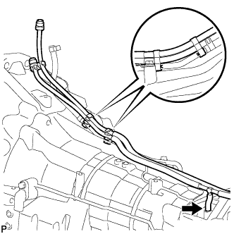
DISCONNECT OIL COOLER TUBE
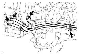
-
Remove the 2 bolts and disconnect the 2 hoses from the transmission, and separate the oil cooler tube from the engine.
-
-
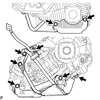
REMOVE AUTOMATIC TRANSMISSION ASSEMBLY
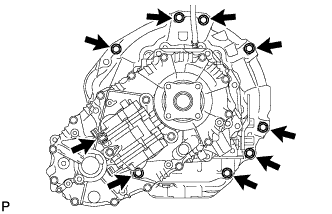
-
Remove the 9 bolts and transmission.
Note
Do not use excess force when prying the transmission assembly.
-
-
REMOVE TRANSFER ASSEMBLY
-
Detach the 2 breather hose clamps from the automatic transmission breather tube.
-
Disconnect the clamp of the ground cable from the transfer case lower protector.
-
Remove the 7 bolts and transfer case lower protector.
-
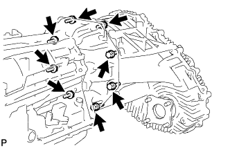
Remove the 8 bolts and transfer.
-
-
REMOVE TORQUE CONVERTER CLUTCH ASSEMBLY
-
INSPECT TORQUE CONVERTER CLUTCH ASSEMBLY
-
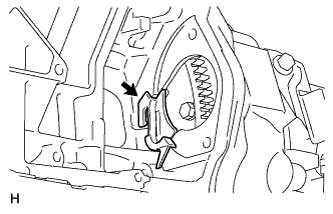
Inspect the 1-way clutch.
-
Install SST to the inner race of the 1-way clutch.
- SST
- 09350-32014 ( 09351-32020 )
-
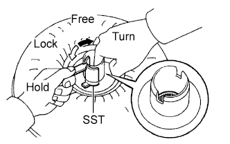
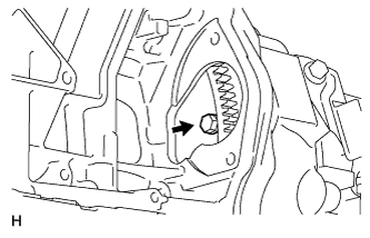
Press on the serrations of the starter with a finger and rotate it.
Check that it rotates smoothly when turned clockwise and locks when turned counterclockwise.
If the results are not as specified, clean the converter and recheck the 1-way clutch. If the results still are not as specified, replace the torque converter clutch assembly.
-
-
Determine the condition of the torque converter clutch.
-
Check that the following conditions are met:
-
During the stall test or when the shift lever is in N, metallic sounds are not emitted from the torque converter clutch.
-
The 1-way clutch turns in one direction and locks in the other direction.
-
The amount of powder in the ATF is not more than the sample shown in the illustration.
If the results are not as specified, replace the torque converter clutch assembly.
Tech Tips
The sample illustration shows approximately 0.25 liters (0.26 US qts, 0.22 Imp. qts) of ATF taken from a removed torque converter clutch.
-
-
-
Replace the ATF in the torque converter clutch.
-
If the ATF is discolored and/or has a foul odor, stir the ATF in the torque converter clutch thoroughly and drain the ATF with the torque converter facing upward.
-
-
Prevent deformation of the torque converter clutch and damage to the oil pump gear.
-
When any marks due to interference are found on the end of the bolt for the torque converter clutch and on the bottom of the bolt hole, replace the bolt and torque converter clutch.
-
All of the bolts should be the same length.
-
Make sure no spring washers are missing.
-
-