-
When replacing an injector (including interchanging injectors between cylinders) or common rail, replace the corresponding injection pipes with new ones.
-
w/DPF
When fuel lines are disconnected, air may enter the fuel lines, leading to engine starting trouble. Therefore, perform forced regeneration and bleed the air from the fuel lines (Click here).
- Click here
INSTALL SCAVENGING PUMP ASSEMBLY
-
Install the scavenging pump with the 4 bolts.
10 N*m 102 kgf*cm 7 ft.*lbf
-
- Click here
INSTALL REAR CRANKSHAFT OIL SEAL
-
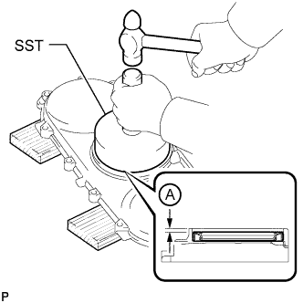
Place the oil seal retainer on wooden blocks.
-
Using SST and a hammer, tap in a new oil seal as shown in the illustration.
09223-56010 Standard depth A 2.7 to 3.7 mm (0.106 to 0.147 in.) Note:
-
Keep the lip free from foreign matter.
-
Do not tap on the seal at an angle.
-
-
- Click here
INSTALL REAR ENGINE OIL SEAL RETAINER
Note: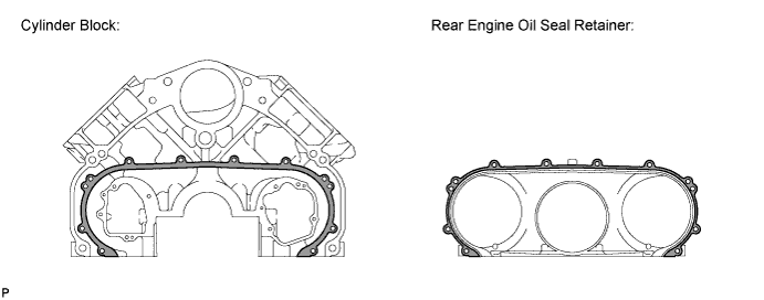
When the contact surfaces shown below are wet, wipe them with an oil-free cloth before applying seal packing.
-
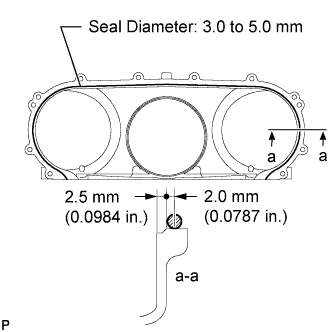
Apply seal packing in a continuous line as shown in the illustration.
Seal diameter 3.0 to 5.0 mm (0.118 to 0.197 in.) Seal packing Toyota Genuine Seal Packing Black, Three Bond 1207B or equivalent Note:
-
Remove any oil from the contact surface.
-
Install the rear engine oil seal retainer within 3 minutes and tighten the bolts within 15 minutes after applying seal packing.
-
-
Apply engine oil to the oil seal lip.
-
Make sure that the lip of the oil seal is properly installed.
-
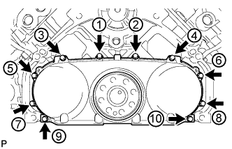
Install and uniformly tighten the 10 bolts in the order shown in the illustration.
10 N*m 102 kgf*cm 7 ft.*lbf Note:
-
When installing the oil seal retainer, make sure the lip of the oil seal is not damaged.
-
When installing the oil seal retainer, make sure the lip of the oil seal is not folded incorrectly.
-
-
-
Click here
INSTALL NO. 1 OIL PAN SUB-ASSEMBLY
Note:When the contact surfaces shown below are wet, wipe them with an oil-free cloth before applying seal packing.
-
Install the cylinder block oil hole gasket.
-
Apply a light coat of engine oil to 3 new O-rings and set the 3 O-rings to the oil regulator and scavenging pump.
-
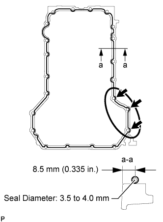
Apply seal packing to the No. 1 oil pan as shown in the illustration.
Standard seal diameter 3.5 to 4.0 mm (0.134 to 0.157 in.) Seal packing Toyota Genuine Seal Packing Black, Three Bond 1207B or equivalent Note:
-
For the 3 bolt holes labeled with arrows, apply the seal packing on the outer edges. For the other bolt holes, apply the seal packing on the inner edges.
-
Make sure to apply a continuous bead of seal packing as shown in the illustration. If the bead breaks, overlap 3 mm (0.118 in.) of seal packing and continue the bead.
-
Remove any oil and old seal packing from the contact surface.
-
Install the No. 1 oil pan within 3 minutes and tighten the bolts and nuts within 15 minutes after applying seal packing.
-
Do not start the engine for at least 2 hours after installing.
-
-
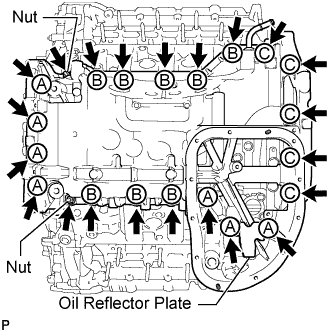
Install the No. 1 oil pan and oil reflector plate with the 20 bolts and 2 nuts.
25 N*m 250 kgf*cm 18 ft.*lbf Table 1. Bolt Length Item Quantity Length Bolt A 7 70 mm (2.76 in.) Bolt B 8 20 mm (0.787 in.) Bolt C 5 30 mm (1.18 in.)
-
- Click here
INSTALL OIL STRAINER SUB-ASSEMBLY
-
Apply a light coat of engine oil to a new O-ring, and install it to the oil strainer.
-
Install the oil strainer with the 2 bolts.
10 N*m 102 kgf*cm 7 ft.*lbf
-
-
Click here
INSTALL NO. 2 OIL PAN SUB-ASSEMBLY
Note:When the contact surfaces shown below are wet, wipe them with an oil-free cloth before applying seal packing.
-
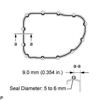
Apply seal packing to the No. 2 oil pan as shown in the illustration.
Standard seal diameter 5.0 to 6.0 mm (0.197 to 0.236 in.) Seal packing Toyota Genuine Seal Packing Black, Three Bond 1207B or equivalent Note:
-
For the bolt and pin holes, make sure to apply seal packing to the inner sides.
-
Make sure to apply a continuous bead of seal packing as shown in the illustration. If the bead breaks, overlap 3.0 mm (0.118 in.) of seal packing and continue the bead.
-
Remove any oil from the contact surface.
-
Install the No. 2 oil pan within 3 minutes and tighten the bolts and nuts within 10 minutes after applying seal packing.
-
Do not start the engine for at least 2 hours after installing.
-
-
Install the No. 2 oil pan with the 10 bolts and 2 nuts.
10 N*m 102 kgf*cm 7 ft.*lbf
-
- Click here
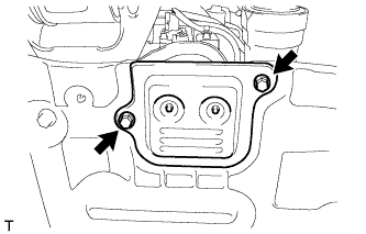
INSTALL ENGINE OIL LEVEL SENSOR
-
Install a new gasket and the sensor with the 4 bolts.
10 N*m 102 kgf*cm 7 ft.*lbf
-
- Click here
INSTALL OIL FILTER BRACKET SUB-ASSEMBLY
-
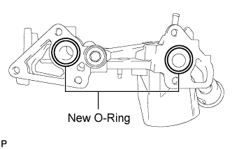
Apply a light coat of engine oil to 2 new O-rings, and set them to the oil filter bracket.
-
Install the oil filter bracket with the 3 bolts and 2 nuts.
21 N*m 214 kgf*cm 15 ft.*lbf -
Connect the 2 wire harness clamps.
-
- Click here
INSTALL OIL FILTER ELEMENT
-
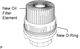
Clean the inside of the oil filter cap, its threads and its O-ring groove.
-
Apply a small amount of engine oil to a new O-ring and install it to the oil filter cap.
-
Set a new oil filter element in the oil filter cap.
-
Remove any dirt or foreign matter from the installation surface of the engine.
-
Apply a small amount of engine oil to the O-ring again and temporarily install the oil filter cap by hand.
-
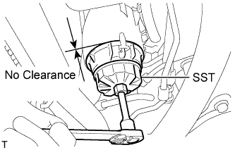
Using SST, tighten the oil filter cap.
09228-06501 25 N*m 255 kgf*cm 18 ft.*lbf Note:
-
Make sure that the oil filter is installed securely as shown in the illustration.
-
Be careful that the O-ring does not get caught between any surrounding parts.
-
-
Install the No. 2 engine under cover seal to the No. 2 engine under cover with the 2 bolts.
10 N*m 102 kgf*cm 7 ft.*lbf
-
- Click here
INSTALL TIMING GEAR COVER SPACER (w/ Intercooler)
-
Install the timing gear cover spacer with the 2 bolts.
21 N*m 214 kgf*cm 15 ft.*lbf
-
- Click here
INSTALL CRANKSHAFT PULLEY
Note:This procedure is intended for removal/installation of the crankshaft pulley only. Do not use this procedure for removal/installation of the flywheel or the drive plate and ring gear.
-
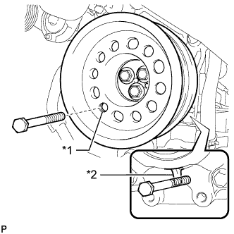
Align the crankshaft pulley and the crankshaft knock pin, and temporarily install the crankshaft pulley with the 3 bolts.
Table 2. Text in Illustration *1 Service Hole *2 Protrusion -
Install the 2 bolts to the bolt holes of the crankshaft rear side.
-
Using a bar, turn the crankshaft until the crankshaft pulley service hole is a little to the right of bottom dead center.
-
Install a 14 mm x 1.5 pitch service bolt with a length of 70 mm or more to the crankshaft pulley service hole, and hold the crankshaft using the timing chain cover protrusion.
-
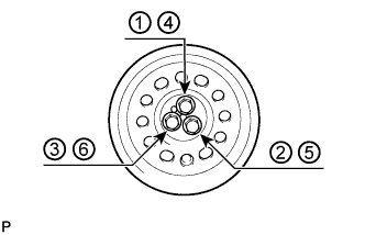
Uniformly tighten the 3 bolts in 2 passes in the order shown in the illustration.
115 N*m 1168 kgf*cm 84 ft.*lbf -
Remove the service bolt.
-
- Click here
INSTALL V-RIBBED BELT TENSIONER ASSEMBLY
-
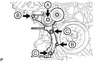
Install the V-ribbed belt tensioner with the 5 bolts.
for bolt A and C 43 N*m 438 kgf*cm 32 ft.*lbf for bolt B 21 N*m 214 kgf*cm 15 ft.*lbf Table 3. Bolt Length Item Quantity Length Bolt A 1 116 mm (4.57 in.) Bolt B 2 40 mm (1.58 in.) Bolt C 2 95 mm (3.74 in.) -
Install the No. 1 idler pulley with the bolt.
43 N*m 438 kgf*cm 32 ft.*lbf -
Install the V-ribbed belt tensioner bracket with the 3 bolts.
10 N*m 102 kgf*cm 7 ft.*lbf
-
- Click here
CONNECT NO. 2 OIL COOLER HOSE
-
Align the white paint marks on the oil cooler hose and oil filter bracket and connect the hose.
Note:Make sure to maintain a space between the oil cooler hose and crankshaft pulley and the oil cooler hose and V-ribbed belt idler pulley.
-
- Click here
CONNECT NO. 1 OIL COOLER HOSE
-
Face the pink paint mark on the oil cooler hose toward the front side of the engine and connect the hose to the oil filter bracket.
Note:Make sure to maintain a space between the oil cooler hose and crankshaft pulley.
-
- Click here
INSTALL STIFFENER INSULATOR RH (w/ Intercooler)
-
Install the stiffener insulator RH with the 2 bolts.
10 N*m 102 kgf*cm 7 ft.*lbf
-
- Click here
INSTALL NO. 2 INLET TURBO OIL PIPE SUB-ASSEMBLY
-
Install a new gasket and connect the No. 2 inlet turbo oil pipe with the union bolt.
29 N*m 296 kgf*cm 21 ft.*lbf
-
- Click here
CONNECT NO. 2 OUTLET TURBO OIL HOSE
- Click here
INSTALL NO. 1 ENGINE OIL LEVEL DIPSTICK GUIDE
-
Apply a light coat of engine oil to a new O-ring, and install it to the No. 1 engine oil level dipstick guide.
-
Install the No. 1 engine oil level dipstick guide with the 2 bolts.
10 N*m 102 kgf*cm 7 ft.*lbf
-
- Click here
CONNECT NO. 1 OUTLET TURBO OIL HOSE
- Click here
INSTALL GENERATOR ASSEMBLY
-
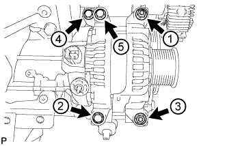
Temporarily install the generator with the 3 bolts and 2 nuts.
-
Uniformly tighten the 3 bolts and 2 nuts in the order shown in the illustration.
21 N*m 214 kgf*cm 15 ft.*lbf -
Connect the generator cable and install the nut and bolt.
for bolt 13 N*m 133 kgf*cm 10 ft.*lbf for nut (130A Type and 150A Type:) 9.8 N*m 100 kgf*cm 87 in.*lbf for nut (180A Type:) 12 N*m 122 kgf*cm 9 ft.*lbf
-
- Click here
INSTALL NO. 1 INTAKE AIR CONNECTOR PIPE
-
Install the No. 1 intake air connector pipe with the bolt. Then tighten the hose clamp.
for bolt 21 N*m 214 kgf*cm 15 ft.*lbf for hose clamp 6.0 N*m 61 kgf*cm 53 in.*lbf -
Connect the 4 connectors and attach the 5 wire harness clamps.
-
- Click here
INSTALL ENGINE ASSEMBLY
-
Install the engine assembly to the vehicle (Click here).
-
- Click here
CONNECT CABLE TO NEGATIVE BATTERY TERMINAL
Note:When disconnecting the cable, some systems need to be initialized after the cable is reconnected (Click here).
-
Connect the cables to negative (-) main battery and sub-battery terminals.
-