OIL PUMP REMOVAL

Note
-
When replacing an injector (including interchanging injectors between cylinders) or common rail, replace the corresponding injection pipes with new ones.
-
w/DPF
When fuel lines are disconnected, air may enter the fuel lines, leading to engine starting trouble. Therefore, perform forced regeneration and bleed the air from the fuel lines.
-
PRECAUTION
Note
After turning the ignition switch off, waiting time may be required before disconnecting the cable from the battery terminal. Therefore, make sure to read the disconnecting the cable from the battery terminal notice before proceeding with work Click here.
-
DISCONNECT CABLE FROM NEGATIVE BATTERY TERMINAL
CAUTION:
Wait at least 90 seconds after disconnecting the cable from the negative (-) battery terminal to disable the SRS system.
Note
When disconnecting the cable, some systems need to be initialized after the cable is reconnected Click here.
-
Disconnect the cables from the negative (-) main battery and sub-battery terminals.
-
-
REMOVE ENGINE ASSEMBLY
-
Remove the engine assembly from the vehicle Click here.
-
-
REMOVE NO. 1 INTAKE AIR CONNECTOR PIPE
-
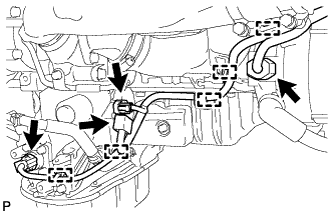
Disconnect the 4 connectors.
-
Using a clip remover, detach the 5 wire harness clamps.
-
Loosen the hose clamp, and remove the bolt and No. 1 intake air connector pipe.
-
-
REMOVE GENERATOR ASSEMBLY
-
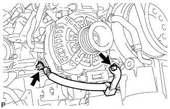
Remove the nut and bolt, and disconnect the generator positive (+) cable.
-
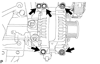
Remove the 3 bolts, 2 nuts and generator.
-
-
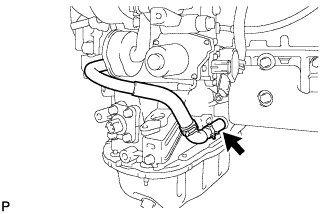
DISCONNECT NO. 1 OUTLET TURBO OIL HOSE
-
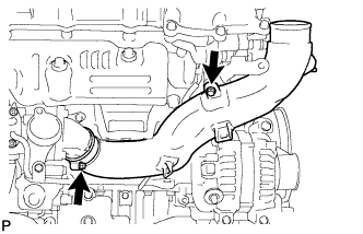
REMOVE NO. 1 ENGINE OIL LEVEL DIPSTICK GUIDE
-
Remove the 2 bolts and No. 1 engine oil level dipstick guide.
-
-
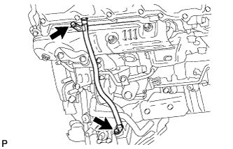
DISCONNECT NO. 2 OUTLET TURBO OIL HOSE
-
DISCONNECT NO. 2 INLET TURBO OIL PIPE SUB-ASSEMBLY
-
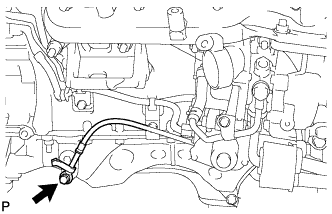
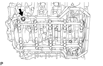
Remove the union bolt and gasket, and disconnect the No. 2 inlet turbo oil pipe.
-
-
REMOVE STIFFENER INSULATOR RH (w/ Intercooler)
-
Remove the 2 bolts and stiffener insulator RH.
-
-
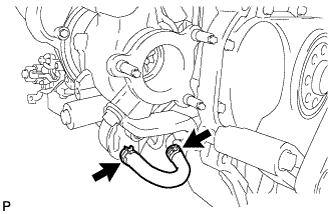
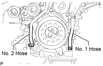
DISCONNECT NO. 1 OIL COOLER HOSE
-
DISCONNECT NO. 2 OIL COOLER HOSE
-
REMOVE V-RIBBED BELT TENSIONER ASSEMBLY
-
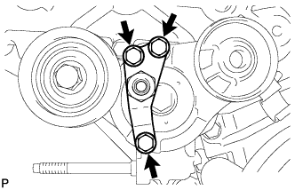
Remove the 3 bolts and V-ribbed belt tensioner bracket.
-
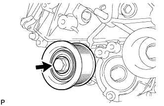
Remove the bolt and No. 1 idler pulley.
-
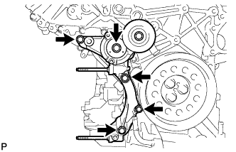
Remove the 5 bolts and V-ribbed belt tensioner.
-
-
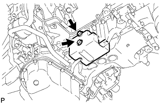
REMOVE CRANKSHAFT PULLEY
Note

This procedure is intended for removal/installation of the crankshaft pulley only. Do not use this procedure for removal/installation of the flywheel or the drive plate and ring gear.
Text in Illustration *1 Service Hole *2 Protrusion
-
Install the 2 bolts to the bolt holes of the crankshaft rear side.
-
Using a bar, turn the crankshaft until the crankshaft pulley service hole is a little to the left of bottom dead center.
-
Install a 14 mm x 1.5 pitch service bolt with a length of 70 mm or more to the crankshaft pulley service hole, and hold the crankshaft using the timing chain cover protrusion.
-
Remove the 3 bolts and crankshaft pulley.
Note
If the crankshaft pulley cannot be removed, temporarily install a bolt to the crankshaft so that the pulley does not fall, and lightly tap the outer edge of the mass damper with a plastic-faced hammer to remove the pulley. Do not tap the pulley V-ribbed belt ribs, as the crankshaft may be damaged.
-
-
REMOVE TIMING GEAR COVER SPACER (w/ Intercooler)
-
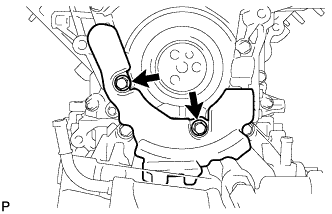
Remove the 2 bolts and timing gear cover spacer.
-
-
REMOVE OIL FILTER ELEMENT
-

Remove the oil filter drain plug.
-
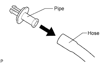
Connect a hose with an inside diameter of 15 mm (0.591 in.) to the pipe.
-
Remove the O-ring from the oil filter drain plug and install it to the drain pipe.
-

Install the oil filter drain pipe to the oil filter cap and drain the engine oil.
-
Remove the oil filter drain pipe.
-
Apply a light coat of engine oil to a new O-ring, and install it to the oil filter drain plug.
-
Install the oil filter drain plug to the oil filter cap.
- Torque:
- 13 N*m { 127 kgf*cm, 9 ft.*lbf }
-
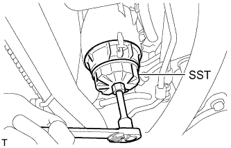
Using SST, remove the oil filter cap.
- SST
- 09228-06501
Tech Tips
Use a container to catch the draining oil. After the oil filter cap is loosened approximately 4 turns and the cap ribs are vertical, engine oil drains from the gap between the oil filter cap and oil pan.
-

Remove the oil filter element and O-ring from the oil filter cap.
Note
Be sure to remove the cap O-ring by hand, without using any tools, to prevent damage to the cap O-ring groove.
-
-
REMOVE OIL FILTER BRACKET SUB-ASSEMBLY
-
Disconnect the 2 wire harness clamps.
-
Remove the 3 bolts, 2 nuts and oil filter bracket.
-
Remove the 2 O-rings.
-
-
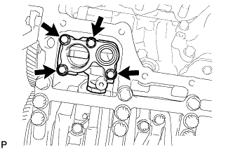
REMOVE ENGINE OIL LEVEL SENSOR
-
Remove the 4 bolts and engine oil level sensor.
-
Remove the gasket.
-
-
REMOVE NO. 2 OIL PAN SUB-ASSEMBLY
-
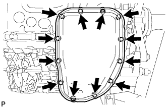
Remove the 10 bolts and 2 nuts.
-

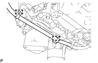
Insert the blade of an oil pan seal cutter between the oil pans. Cut through the applied sealer and remove the No. 2 oil pan.
Note
Be careful not to damage the contact surfaces of the No. 1 and No. 2 oil pans.
-
-
REMOVE OIL STRAINER SUB-ASSEMBLY
-
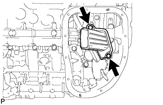
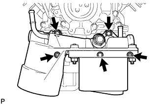
Remove the 2 bolts and oil strainer.
-
Remove the O-ring from the oil strainer.
-
-
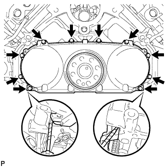
REMOVE NO. 1 OIL PAN SUB-ASSEMBLY
-
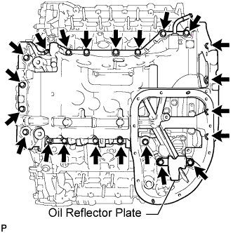
Remove the 20 bolts, 2 nuts and oil reflector plate.
Note
If the oil reflector plate is deformed, replace it.
Tech Tips
Be sure to clean the bolts and stud bolts, and check the threads for cracks or other damage.
-
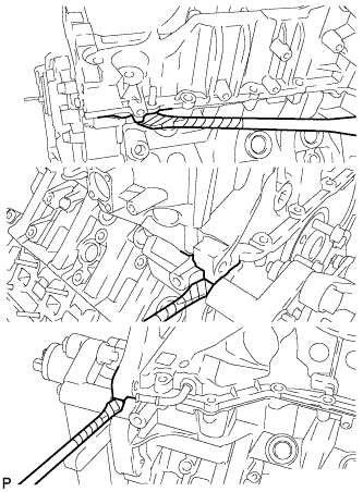
Remove the No. 1 oil pan by prying between the No. 1 oil pan and cylinder block with a screwdriver.
Note
Be careful not to damage the contact surfaces of the cylinder block and oil pan.
Tech Tips
Tape the screwdriver tip before use.
-

Remove the 3 O-rings.
-
Remove the cylinder block oil hole gasket.
-
-
REMOVE OIL REGULATOR ASSEMBLY
-
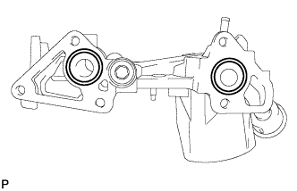
Remove the 4 bolts and oil regulator.
-
-
REMOVE REAR ENGINE OIL SEAL RETAINER
-
Remove the 10 bolts.
-
Remove the oil seal retainer by prying between the oil seal retainer and cylinder block with a screwdriver.
Tech Tips
Tape the screwdriver tip before use.
-
-
REMOVE REAR CRANKSHAFT OIL SEAL
-

Place the oil seal retainer on wooden blocks.
-
Using a screwdriver and hammer, tap out the oil seal.
Tech Tips
Tape the screwdriver tip before use.
-
-
REMOVE OIL PUMP ASSEMBLY
-
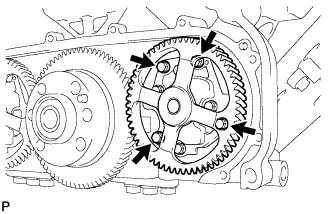
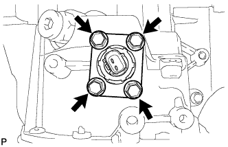
Remove the 4 bolts and oil pump.
-