- Click here
PRECAUTION
Note:After turning the ignition switch off, waiting time may be required before disconnecting the cable from the battery terminal. Therefore, make sure to read the disconnecting the cable from the battery terminal notice before proceeding with work (Click here).
- Click here
DISCONNECT CABLE FROM NEGATIVE BATTERY TERMINAL
Note:When disconnecting the cable, some systems need to be initialized after the cable is reconnected (Click here).
-
Disconnect the cables from the negative (-) main battery and sub-battery terminals.
-
- Click here
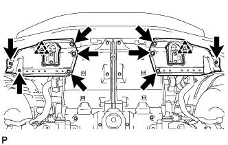
REMOVE UPPER RADIATOR SUPPORT SEAL
-
Remove the 7 clips and upper radiator support seal.
-
- Click here
REMOVE FRONT WHEEL RH
- Click here
REMOVE FRONT FENDER APRON SEAL FRONT RH
-
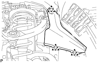
Remove the 3 clips and front fender apron seal front RH.
-
- Click here
REMOVE FRONT FENDER SPLASH SHIELD SUB-ASSEMBLY LH
-
Remove the 3 bolts and screw.
-
Loosen the clip and remove the front fender splash shield LH.
-
- Click here
REMOVE FRONT FENDER SPLASH SHIELD SUB-ASSEMBLY RH
-
Remove the 3 bolts and 2 screws.
-
Loosen the clip and remove the front fender splash shield RH.
-
- Click here
REMOVE NO. 1 ENGINE UNDER COVER SUB-ASSEMBLY
-
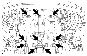
Remove the 10 bolts and No. 1 engine under cover.
-
- Click here
DRAIN ENGINE COOLANT
CAUTION:Do not remove the radiator reservoir cap while the engine and radiator are still hot. Pressurized, hot engine coolant and steam may be released and cause serious burns.
Tip:Collect the coolant in a container and dispose of it according to the regulations in your area.
-
Loosen the radiator drain cock plug.
-
Remove the radiator reservoir cap to drain the coolant in the radiator.
-
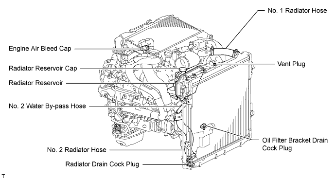
Loosen the oil filter bracket drain cock plug to drain the coolant in the engine.
-
Tighten the radiator drain cock plug by hand.
-
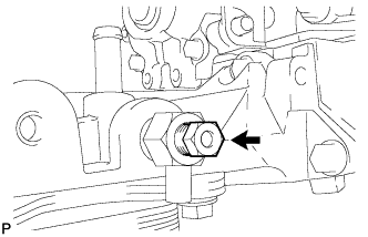
Tighten the oil filter bracket drain cock plug.
13 N*m 133 kgf*cm 10 ft.*lbf
-
- Click here
REMOVE NO. 3 ENGINE ROOM WIRE
-
Disconnect the 4 wire harness clamps.
-
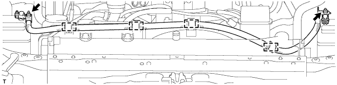
Remove the 2 nuts and No. 3 engine room wire.
-
- Click here
REMOVE NO. 1 ENGINE COVER SUB-ASSEMBLY (w/ Intercooler)
-
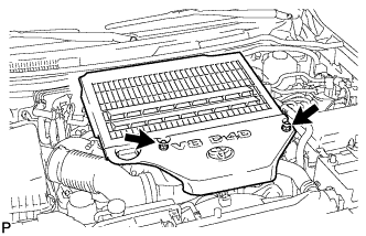
Remove the 2 nuts and No. 1 engine cover.
-
- Click here
REMOVE AIR CLEANER CAP SUB-ASSEMBLY
-
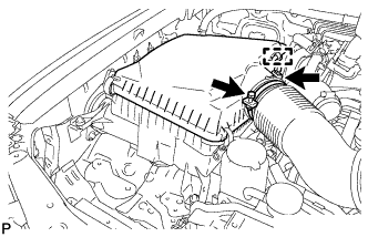
Loosen the hose clamp.
-
Disconnect the mass air flow meter connector and using a clip remover, detach the wire harness clamp from the air cleaner cap.
-
Detach the 4 clamps and remove the air cleaner cap.
-
- Click here
REMOVE NO. 1 AIR CLEANER HOSE
-
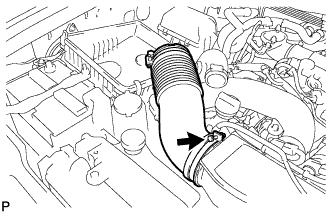
Loosen the hose clamp and remove the No. 1 air cleaner hose.
-
- Click here
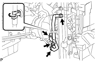
REMOVE INTAKE AIR CONNECTOR
-
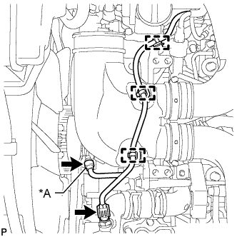
w/ Viscous Heater:
Disconnect the 2 connectors from the viscous with magnet clutch heater and water temperature sensor.
Table 1. Text in Illustration *A w/ Viscous Heater -
w/o Viscous Heater:
Disconnect the connector from the water temperature sensor.
-
Using a clip remover, detach the 3 wire harness clamps.
-
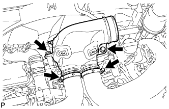
Loosen the 2 hose clamps and remove the 2 bolts and intake air connector.
-
- Click here
REMOVE VANE PUMP OIL RESERVOIR ASSEMBLY
-
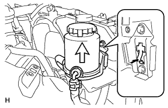
Insert a screwdriver between the reservoir and oil reservoir bracket, push the claw, and then disconnect the reservoir by pulling it upwards.
-
- Click here
REMOVE NO. 1 OIL RESERVOIR BRACKET
-
Remove the 2 bolts and bracket.
-
- Click here
REMOVE RADIATOR RESERVOIR ASSEMBLY
-
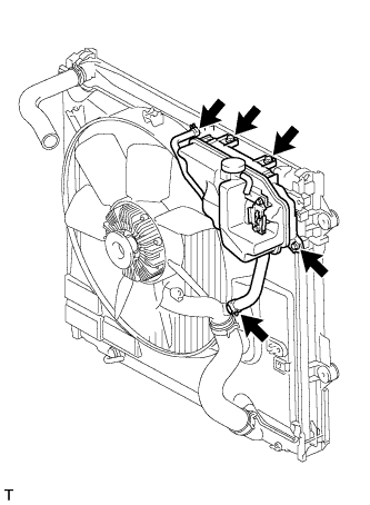
Disconnect the 2 hoses.
-
Remove the 3 bolts and radiator reservoir.
-
- Click here
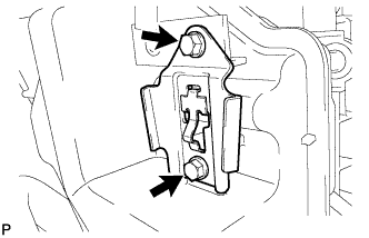
REMOVE VANE PUMP ASSEMBLY
-
Remove the 2 nuts and vane pump.
-
Remove the O-ring from the vane pump.
-
- Click here
DISCONNECT NO. 1 RADIATOR HOSE
- Click here
DISCONNECT NO. 2 RADIATOR HOSE
- Click here
REMOVE V-RIBBED BELT (w/ Viscous Heater)
-
Loosen the lock nut and turn the bolt counterclockwise.
-
Remove the V-ribbed belt.
-
- Click here
REMOVE NO. 1 IDLER PULLEY (w/ Viscous Heater)
-
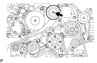
Remove the bolt, cover, No. 1 idler pulley and collar.
-
- Click here
REMOVE NO. 3 IDLER PULLEY (w/ Viscous Heater)
-
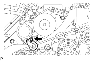
Remove the nut and No. 3 idler pulley.
-
- Click here
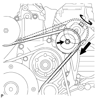
REMOVE V-RIBBED BELT
-
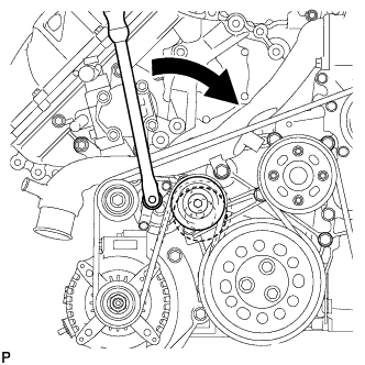
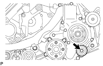
Using a wrench to the V-ribbed belt tensioner bracket, turn the wrench clockwise and remove the V-ribbed belt.
-
- Click here
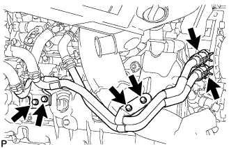
REMOVE OIL COOLER TUBE (for Automatic Transmission)
-
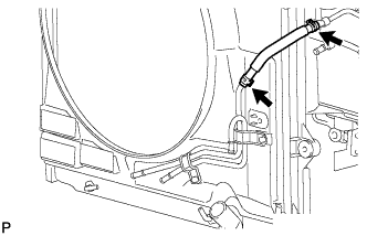
Disconnect the inlet and outlet No. 1 oil cooler hose.
-
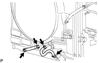
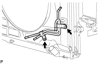
Disconnect the inlet No. 2 and No. 3 oil cooler hoses.
-
Disconnect the inlet No. 4 oil cooler hose.
-
Remove the 2 bolts and transmission oil cooler tube.
-
- Click here
REMOVE FAN SHROUD WITH FAN
-
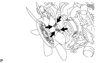
Loosen the 4 nuts holding the fluid coupling fan.
-
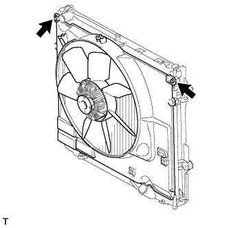
Remove the 2 bolts holding the fan shroud.
-
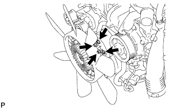
Remove the 4 nuts of the fluid coupling fan, and then remove the shroud together with the fluid coupling fan.
-
- Click here
REMOVE FAN PULLEY
- Click here
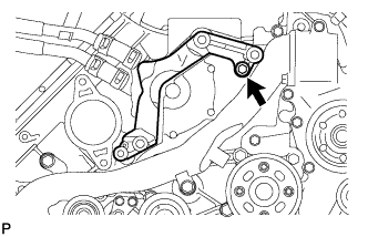
REMOVE HEATER WATER PIPE SUB-ASSEMBLY (w/ Viscous Heater)
-
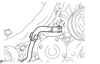
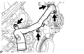
Remove the 4 bolts and disconnect the heater water pipe from the viscous heater with magnet clutch.
-
-
Click here
REMOVE VISCOUS WITH MAGNET CLUTCH HEATER ASSEMBLY (w/ Viscous Heater)
-
Disconnect the connector and detach the clamp.
-
Using pliers, grip the claws of the clips and slide the 2 clips.
-
Disconnect the 2 heater hoses.
-
Remove the 2 bolts and heater assembly.
-
- Click here
REMOVE NO. 1 IDLER PULLEY BRACKET (w/ Viscous Heater)
-
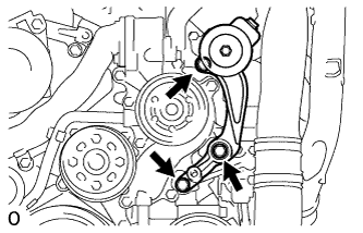
Remove the bolt and No. 1 idler pulley bracket.
-
- Click here
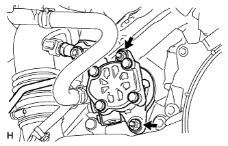
REMOVE WATER INLET
-
Disconnect the No. 2 oil cooler hose from the water pump and clamp.
-
Remove the 4 bolts and water inlet.
-
- Click here
REMOVE THERMOSTAT
-
Remove the thermostat.
-
Remove the gasket from the thermostat.
-
- Click here
REMOVE NO. 2 IDLER PULLEY (w/ Viscous Heater)
-
Remove the bolt, cover, No. 2 idler pulley and collar.
-
- Click here
REMOVE NO. 2 IDLER PULLEY BRACKET (w/ Viscous Heater)
-
Remove the 3 bolts and idler pulley bracket.
-
-
Click here
DISCONNECT NO. 1 OIL COOLER HOSE
- Click here
REMOVE FAN BRACKET SUB-ASSEMBLY
-
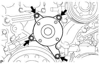
Remove the 4 bolts and fan bracket.
-
- Click here
REMOVE WATER OUTLET
-
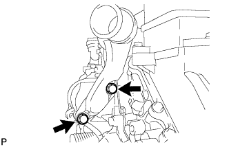
Disconnect the engine coolant temperature sensor connector.
-
Remove the 2 bolts, disconnect the water outlet from the No. 2 water hose joint, and remove the water outlet and gasket.
-
- Click here
REMOVE WATER PUMP ASSEMBLY
-
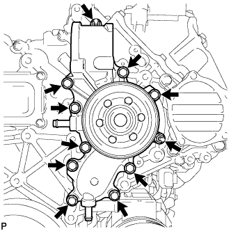
Remove the 9 bolts, 2 nuts, water pump and gasket.
-