INTAKE MANIFOLD REMOVAL

Note
-
When replacing the injectors (including shuffling the injectors between the cylinders), common rail, cylinder head, or intake manifold, it is necessary to replace the injection pipes with new ones.
-
w/ DPF:
When fuel lines are disconnected, air may enter the fuel lines, leading to engine starting trouble. Therefore, perform forced regeneration and bleed the air from the fuel lines.
-
PRECAUTION
Note
After turning the ignition switch off, waiting time may be required before disconnecting the cable from the battery terminal. Therefore, make sure to read the disconnecting the cable from the battery terminal notice before proceeding with work Click here.
-
DISCONNECT CABLE FROM NEGATIVE BATTERY TERMINAL
Note
When disconnecting the cable some systems need to be initialized after the cable is reconnected Click here.
-
REMOVE FRONT FENDER SPLASH SHIELD SUB-ASSEMBLY LH
-
Remove the 3 bolts and screw.
-
Loosen the clip and remove the front fender splash shield LH.
-
-
REMOVE FRONT FENDER SPLASH SHIELD SUB-ASSEMBLY RH
-
Remove the 3 bolts and 2 screws.
-
Loosen the clip and remove the front fender splash shield RH.
-
-
REMOVE NO. 1 ENGINE UNDER COVER SUB-ASSEMBLY
-
Remove the 10 bolts and No. 1 engine under cover.
-
-
REMOVE UPPER RADIATOR SUPPORT SEAL
-
Remove the 7 clips and upper radiator support seal.
-
-
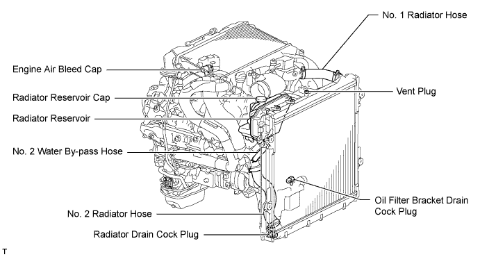
DRAIN ENGINE COOLANT
CAUTION:
Do not remove the radiator reservoir cap while the engine and radiator are still hot. Pressurized, hot engine coolant and steam may be released and cause serious burns.
Tech Tips
Collect the coolant in a container and dispose of it according to the regulations in your area.
-
Loosen the radiator drain cock plug.
-
Remove the radiator reservoir cap to drain the coolant in the radiator.
-
Loosen the oil filter bracket drain cock plug to drain the coolant in the engine.
-
Tighten the radiator drain cock plug by hand.
-
Tighten the oil filter bracket drain cock plug.
- Torque:
- 13 N*m { 133 kgf*cm, 10 ft.*lbf }
-
-
REMOVE INTERCOOLER ASSEMBLY (w/ Intercooler)
-
REMOVE AIR CLEANER CAP SUB-ASSEMBLY
-
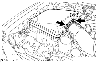
Loosen the hose clamp.
-
Disconnect the mass air flow meter connector and using a clip remover, detach the wire harness clamp from the air cleaner cap.
-
Detach the 4 clamps and remove the air cleaner cap.
-
-
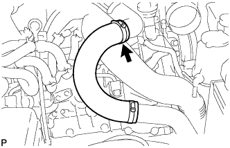
REMOVE NO. 1 AIR CLEANER HOSE
-
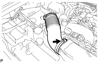
Loosen the hose clamp and remove the No. 1 air cleaner hose.
-
-
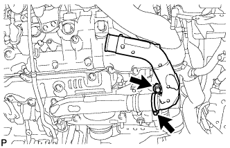
REMOVE INTAKE AIR CONNECTOR
-
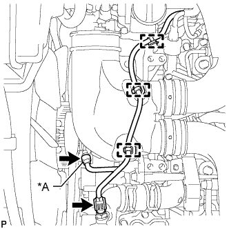
Text in Illustration *A w/ Viscous Heater w/ Viscous Heater:
Disconnect the 2 connectors from the viscous with magnet clutch heater and water temperature sensor.
-
w/o Viscous Heater:
Disconnect the connector from the water temperature sensor.
-
Using a clip remover, detach the 3 wire harness clamps.
-
Loosen the 2 hose clamps and remove the 2 bolts and intake air connector.
-
-
REMOVE NO. 1 COOL AIR INLET (w/o Intercooler)
-
Loosen the No. 1 air hose clamp.
-
Disconnect the turbo pressure sensor connector, intake air temperature sensor connector and vacuum hose.
-
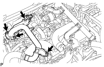
Remove the 3 nuts, bolt and No. 1 cool air inlet.
-
Remove the gasket from the air tube RH.
-
-
REMOVE NO. 2 COOL AIR INLET (w/o Intercooler)
-
Loosen the No. 2 air hose clamp.
-
Remove the 3 nuts, bolt and No. 2 cool air inlet.
-
Remove the gasket from the air tube LH.
-
-
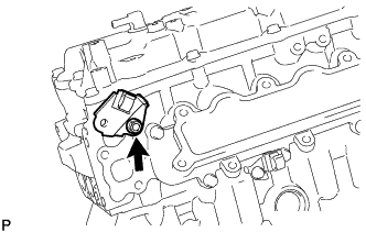
REMOVE NO. 2 ENGINE OIL LEVEL DIPSTICK GUIDE
-
Disconnect the wire harness clamp from the No. 2 engine oil level dipstick guide.
-
Text in Illustration *A w/ DPF *B w/o DPF Disconnect the ventilation hose from the cylinder head cover RH.
-
Remove the 2 bolts and No. 2 engine oil level dipstick guide.
-
Remove the O-ring from the No. 2 engine oil level dipstick guide.
-
-
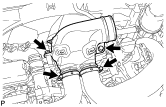
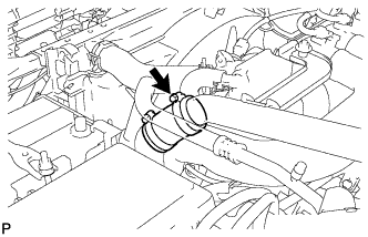
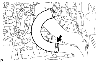
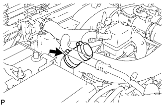
REMOVE AIR TUBE SUB-ASSEMBLY RH
-
Loosen the hose clamp.
-
Remove the air tube from the throttle body.
-
-
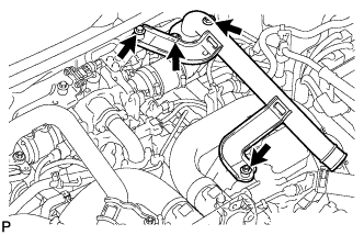
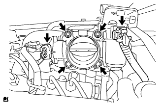
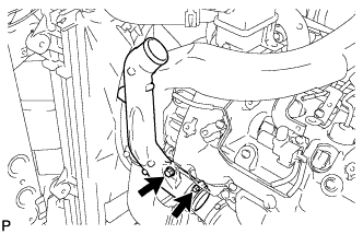
REMOVE DIESEL THROTTLE BODY ASSEMBLY RH
-
Disconnect the throttle position sensor connector.
-
Disconnect the throttle motor connector.
-
Remove the 2 bolts, 2 nuts and throttle body.
-
Remove the gasket from the intake pipe.
-
-
DRAIN CLUTCH FLUID (for Manual Transmission)
-
REMOVE CLUTCH HOSE (for Manual Transmission)
-
Disconnect the 2 flexible hose tubes from the clutch hose with a 10 mm union nut wrench while holding the flexible hose with a wrench.
Note
-
Do not bend or damage the flexible hose tubes.
-
Do not allow any foreign matter such as dirt and dust to enter the flexible hose tubes from the connecting point.
-
-
Remove the 2 clips.
-
Remove the bolt and clutch hose.
-
-
REMOVE AIR TUBE SUB-ASSEMBLY LH
-
Loosen the hose clamp.
-
Remove the air tube from the throttle body.
-
-
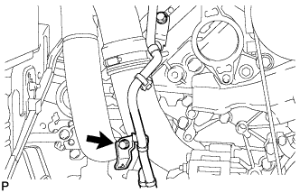
REMOVE TUBE CONNECTOR TO FLEXIBLE HOSE TUBE (for Manual Transmission)
-
Using a 10 mm union nut wrench, disconnect the tube connector to flexible hose tube from the clutch tube to release cylinder 2 way.
Note
-
Do not bend or damage the flexible hose tube.
-
Do not allow any foreign matter such as dirt and dust to enter the flexible hose tube from the connecting point.
-
-
Remove the 2 bolts and tube connector to flexible hose tube.
-
-
REMOVE NO. 1 GAS FILTER
-
Disconnect the hose from the intake pipe.
-
Remove the No. 1 gas filter.
-
-
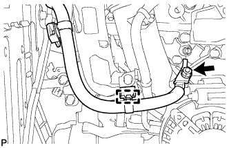
REMOVE NO. 3 INTERCOOLER SUPPORT BRACKET
-
for Manual Transmission:
-
Remove the bolt and disconnect the clutch tube to release cylinder 2 way from the No. 3 intercooler support bracket.
-
-
Remove the 2 bolts and No. 3 intercooler support bracket.
-
-
REMOVE DIESEL THROTTLE BODY ASSEMBLY LH
-
Disconnect the throttle position sensor connector.
-
Disconnect the throttle motor connector.
-
Remove the 2 bolts, 2 nuts and throttle body.
-
Remove the gasket from the intake pipe.
-
-
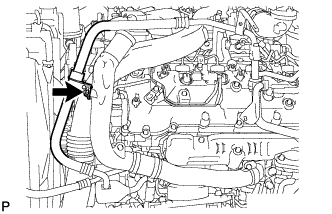
REMOVE NO. 1 AIR HOSE
-
Loosen the hose clamp and remove the No. 1 air hose.
-
-
REMOVE NO. 3 AIR TUBE
-
Disconnect the wire harness from the clamp.
-
Remove the nut and ground wire.
-
Remove the bolt and disconnect the wire harness bracket.
-
Loosen the hose clamp and remove the bolt and No. 3 air tube.
-
-
REMOVE NO. 2 AIR HOSE
-
Loosen the hose clamp and remove the No. 2 air hose.
-
-
REMOVE NO. 4 AIR TUBE
-
Remove the bolt and disconnect the suction hose.
-
Loosen the hose clamp and remove the bolt and No. 4 air tube.
-
-
REMOVE NO. 2 AIR CLEANER PIPE SUB-ASSEMBLY
-
Disconnect the ventilation hose from the oil separator.
-
Loosen the hose clamp.
-
Remove the bolt and No. 2 air cleaner pipe.
-
-
DISCONNECT WATER HOSE SUB-ASSEMBLY
Text in Illustration *A w/ Rear Heater *B w/o Rear Heater -
REMOVE HEATER WATER PIPE SUB-ASSEMBLY (w/ Viscous Heater)
-
Remove the 4 bolts and disconnect the 4 water hose ends, and then remove the heater water pipe.
-
-
REMOVE NO. 1 AIR CLEANER PIPE SUB-ASSEMBLY
-
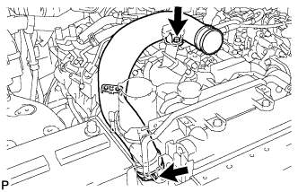
Loosen the hose clamp.
-
Remove the bolt and No. 1 air cleaner pipe.
-
-
DISCONNECT FUEL HOSE
-
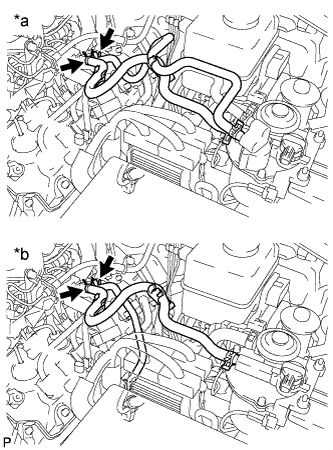
Text in Illustration *a for Fuel Filter with Heater *b for Fuel Filter without Heater w/ DPF:
-
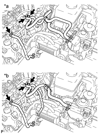
Text in Illustration *a for Fuel Filter with Heater *b for Fuel Filter without Heater w/o DPF:
-
-
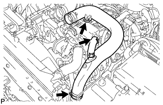
REMOVE NO. 3 WATER BY-PASS PIPE (w/o Viscous Heater)
-
Remove the 2 bolts and disconnect the 2 water hose ends, and then remove the No. 3 water by-pass pipe.
-
-
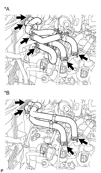
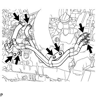
REMOVE NO. 4 WATER BY-PASS PIPE
-
w/ EGR System:
-
Remove the 2 bolts and nut.
Text in Illustration *A w/ DPF *B w/o DPF -
w/ DPF:
Disconnect the 3 water hose ends, and then remove the No. 4 water by-pass pipe.
-
w/o DPF:
Disconnect the 4 water hose ends, and then remove the No. 4 water by-pass pipe.
-
-
w/o EGR System:
-
Remove the 2 bolts and nut.
-
Disconnect the 3 water hose ends, and then remove the No. 4 water by-pass pipe.
-
-
-
DISCONNECT ENGINE WIRE
-
LH Side:
-
Disconnect the 4 connectors.
-
Using a clip remover, detach the 3 wire harness clamps.
-
Disconnect the 2 connectors.
-
Using a clip remover, detach the 3 wire harness clamps.
-
Disconnect the 8 connectors.
Text in Illustration *A w/ DPF *B w/o DPF -
Remove the bolt and engine wire harness bracket labeled B.
-
Using a clip remover, detach the wire harness clamp labeled D.
-
Remove the 2 bolts and disconnect the engine wire protector labeled A.
-
for RHD:
Disconnect the wire harness from the wire harness clamp holder labeled C.
-
-
RH Side:
-
Disconnect the 7 connectors.
Text in Illustration *A w/ DPF *B w/o DPF -
Using a clip remover, detach the wire harness clamp.
-
Remove the 3 bolts and disconnect the wire harness protector labeled A.
-
Remove the bolt and wire harness bracket labeled B.
-
Remove the screw grommet, nut and glow plug wire harness labeled C.
-
Text in Illustration *A w/ DPF *B w/o DPF for RHD:
Disconnect the wire harness from the wire harness clamp holder.
-
for RHD:
Remove the bolt and wire harness clamp holder.
-
-
Rear Side:
-
Text in Illustration *A w/ DPF *B w/o DPF Using a clip remover, detach the wire harness clamp.
-
Remove the 2 bolts and 2 ground wires labeled C.
-
Remove the 2 bolts and disconnect the engine wire harness protector labeled B.
-
w/ DPF:
Disconnect the 3 connectors.
-
w/o DPF:
Disconnect the connector.
-
Remove the screw grommet, nut and disconnect the glow plug wire harness labeled A.
-
-
-
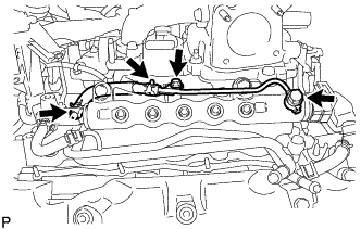
REMOVE NO. 2 FUEL PIPE SUB-ASSEMBLY (w/o DPF)
Note
-
After removing a fuel pipe, to prevent dirt or foreign objects from entering the fuel pipe ends, cover the fuel pipe ends with plastic bags.
-
After removing a fuel pipe, to prevent dirt or foreign objects from entering the fuel supply pump hole, cover the hole with protective tape.
-
Disconnect the fuel hose from the No. 5 nozzle leakage pipe.
-
Remove the bolt and No. 2 injection pipe clamp.
-
Remove the union bolt and gasket.
-
Remove the bolt, nut and No. 2 fuel pipe.
-
-
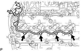
REMOVE NO. 6 INJECTION PIPE SUB-ASSEMBLY
Note
After removing an injection pipe, to prevent dirt or foreign objects from entering the common rail holes, cover the holes with protective tape.
-
w/ EGR System:
-
Using a union nut wrench, loosen the No. 6 injection pipe ends.
-
Remove the 2 nuts and 2 No. 2 injection pipe clamps.
-
Remove the No. 6 injection pipe.
-
-
w/o EGR System:
-
Using a union nut wrench, loosen the No. 6 injection pipe ends.
-
Remove the nut and No. 2 injection pipe clamp.
-
Remove the bolt and No. 6 injection pipe.
-
-
-
REMOVE NO. 1 VACUUM SWITCHING VALVE ASSEMBLY (w/ DPF)
-
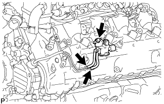
Disconnect the 2 vacuum hoses.
-
Remove the bolt and vacuum switching valve.
-
-
REMOVE NO. 1 VACUUM TRANSMITTING PIPE SUB-ASSEMBLY (w/ DPF)
-
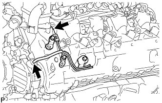
Disconnect the 2 vacuum hoses.
-
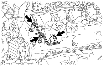
Remove the 3 bolts and vacuum transmitting pipe.
-
-
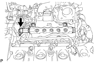
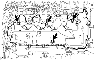
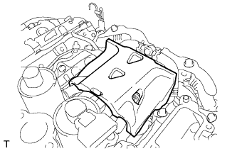
REMOVE CYLINDER HEAD COVER SILENCER LH (w/ DPF)
-
Remove the 4 bolts and cylinder head cover silencer.
-
-
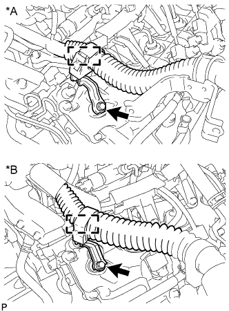
REMOVE NO. 4 NOZZLE LEAKAGE PIPE (w/ DPF)
-
Disconnect the fuel hose.
-
Remove the fuel check valve, No. 4 nozzle leakage pipe and gasket.
-
-
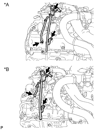
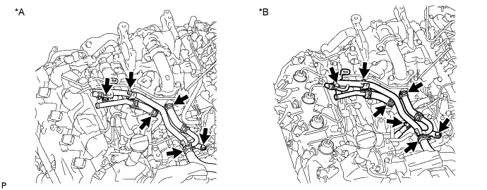
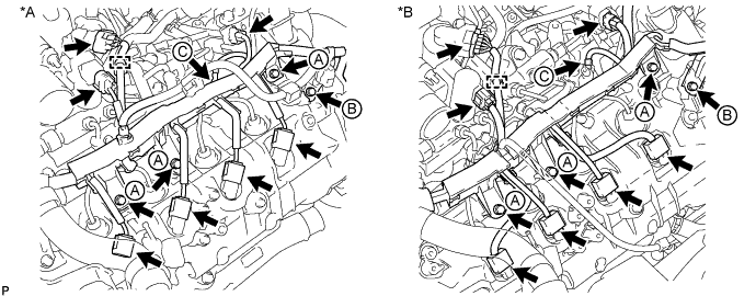
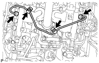
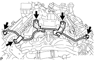
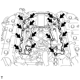
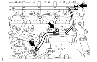
REMOVE INJECTION PIPE LH
-
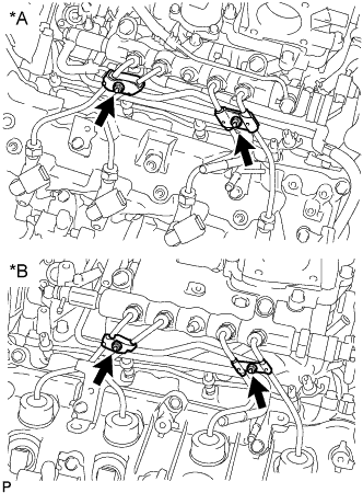
Text in Illustration *A w/ DPF *B w/o DPF w/ Intercooler:
Remove the 2 nuts and 4 injection pipe clamps.
-
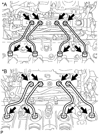
Text in Illustration *A w/ DPF *B w/o DPF Using a union nut wrench, remove the 4 injection pipes.
Note
After removing an injection pipe, to prevent dirt or foreign objects from entering the common rail holes or injector holes, cover the holes with protective tape.
-
-
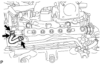
REMOVE NO. 2 FUEL PIPE (w/ DPF)
-
Remove the No. 4 fuel hose.
-
Remove the union bolt, gasket, bolt, and No. 2 fuel pipe.
-
-
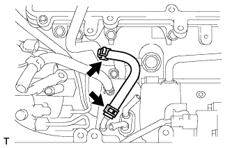
REMOVE NO. 5 NOZZLE LEAKAGE PIPE (w/ DPF)
-
w/ DPF:
-
Disconnect the fuel hose.
-
Remove the union bolt, gasket and No. 5 nozzle leakage pipe.
-
-
w/o DPF:
Remove the union bolt, gasket and No. 5 nozzle leakage pipe.
-
-
REMOVE COMMON RAIL ASSEMBLY LH
-
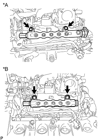
Text in Illustration *A w/ DPF *B w/o DPF Remove the 2 bolts and common rail.
Note
-
Do not remove the fuel pressure limiter from the common rail. If it is removed, replace the common rail.
-
w/ DPF:
Do not remove the pressure discharge valve from the common rail. If it is removed, replace the common rail.
-
-
-
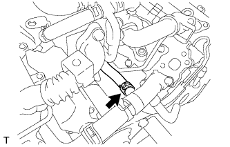
REMOVE FUEL FILTER TO INJECTION PUMP FUEL PIPE SUB-ASSEMBLY
-
w/ DPF:
-
Remove the bolt and No. 2 injection pipe clamp.
-
Disconnect the fuel hose.
-
Remove the union bolt, nut, bolt, fuel filter to injection pump fuel pipe and gasket.
-
-
w/o DPF:
-
Disconnect the 2 hoses from the fuel pipe.
-
Remove the bolt and fuel filter to injection pump fuel pipe.
-
-
-
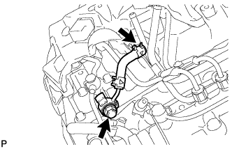
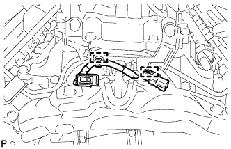
DISCONNECT FUEL PUMP MOTOR WIRE
-
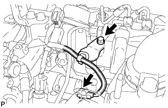
Remove the bolt and disconnect the connector from the fuel supply pump.
-
-
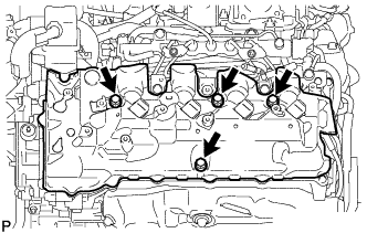
REMOVE NO. 5 INJECTION PIPE SUB-ASSEMBLY
-
Using a union nut wrench, remove the No. 5 injection pipe.
Note
After removing an injection pipe, to prevent dirt or foreign objects from entering the common rail hole or injection pump hole, cover the holes with protective tape.
-
-
REMOVE CYLINDER HEAD COVER SILENCER RH (w/ DPF)
-
Remove the 4 bolts and cylinder head cover silencer.
-
-
REMOVE NO. 2 FUEL INJECTOR PROTECTOR (w/ DPF)
-
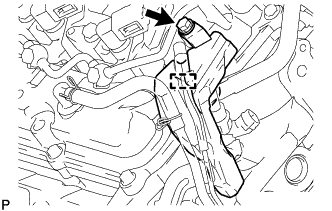
Detach the hose clamp.
-
Remove the bolt and No. 2 fuel injector protector.
-
-
REMOVE NO. 1 FUEL INJECTOR PROTECTOR (w/ DPF)
-
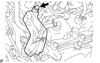
Remove the bolt and No. 1 fuel injector protector.
-
-
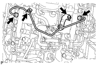
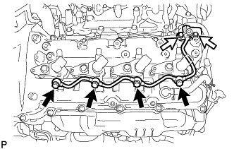
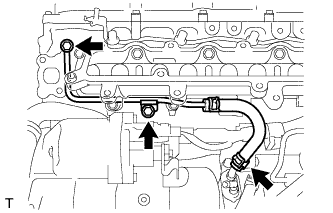
REMOVE INJECTION PIPE RH
-
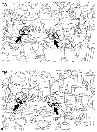
Text in Illustration *A w/ DPF *B w/o DPF w/ Intercooler:
Remove the 2 nuts and 4 injection pipe clamps.
-
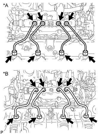
Text in Illustration *A w/ DPF *B w/o DPF Using a union nut wrench, remove the 4 injection pipes.
Note
After removing an injection pipe, to prevent dirt or foreign objects from entering the common rail holes or injector holes, cover the holes with protective tape.
-
-
REMOVE COMMON RAIL ASSEMBLY RH
-
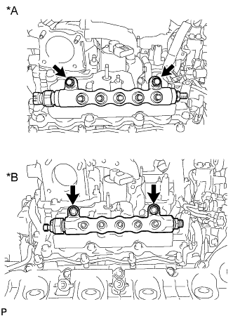
Text in Illustration *A w/ DPF *B w/o DPF Remove the 2 bolts and common rail.
Note
Do not remove the fuel pressure sensor from the common rail. If it is removed, replace the common rail.
-
-
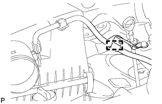
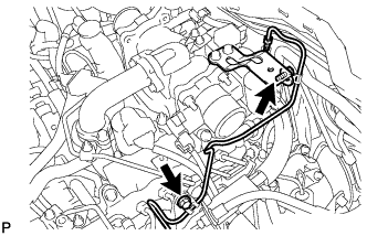
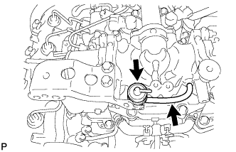
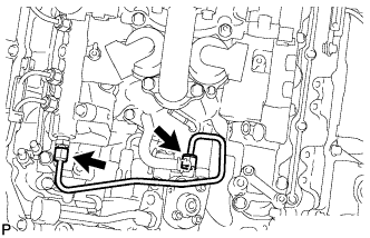
REMOVE CONNECTING WIRE (w/ DPF)
-
Detach the 2 clamps and remove the connecting wire.
-
-
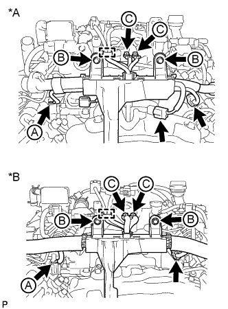
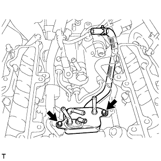
REMOVE NO. 3 NOZZLE LEAKAGE PIPE (w/ DPF)
-
Remove the 2 injector hollow screws, 3 bolts, No. 3 nozzle leakage pipe and 2 gaskets.
-
-
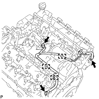
REMOVE NO. 2 NOZZLE LEAKAGE PIPE (w/ DPF)
-
Remove the 4 injector hollow screws and 4 gaskets.
Text in Illustration 
Injector Hollow Screw 
Bolt -
Remove the 2 bolts and No. 2 nozzle leakage pipe.
Note
-
When removing the nozzle leakage pipe, place a cushion under the pipe.
-
Be careful not to deform or scratch the union seal surface.
-
After removing the nozzle leakage pipe, put it in a plastic bag to prevent foreign matter from contaminating its injector inlet.
-
-
-
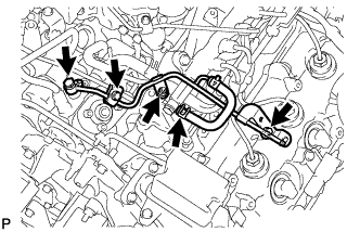
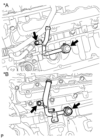
REMOVE NO. 1 NOZZLE LEAKAGE PIPE (w/ DPF)
-
Remove the 4 injector hollow screws and 4 gaskets.
Text in Illustration Injector Hollow Screw No. 2 Check Valve 
Union Bolt -
Remove the No. 2 check valve from the fuel tube and No. 1 nozzle leakage pipe.
-
Remove the union bolt and No. 1 nozzle leakage pipe.
Note
-
When removing the nozzle leakage pipe, place a cushion under the pipe.
-
Be careful not to deform or scratch the union seal surface.
-
After removing the nozzle leakage pipe, put it in a plastic bag to prevent foreign matter from contaminating its injector inlet.
-
-
-
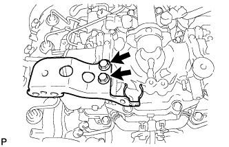
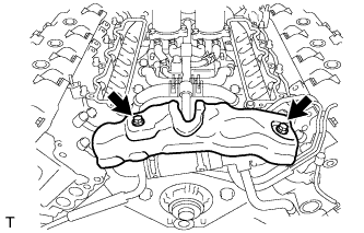
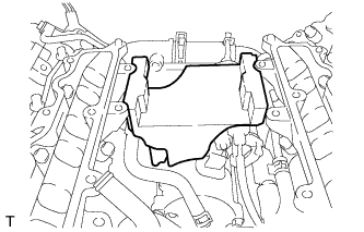
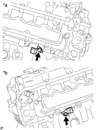
REMOVE NO. 1 INTAKE MANIFOLD INSULATOR (w/ Intercooler)
-
REMOVE NO. 2 INTAKE MANIFOLD INSULATOR (w/ Intercooler)
-
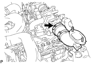
REMOVE INTAKE PIPE
-
w/ EGR System:
Remove the 2 nuts, 6 bolts, intake pipe and 2 gaskets.
-
w/o EGR System:
Remove the 2 nuts, 4 bolts, intake pipe and gasket.
-
-
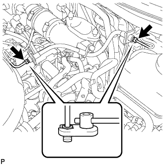
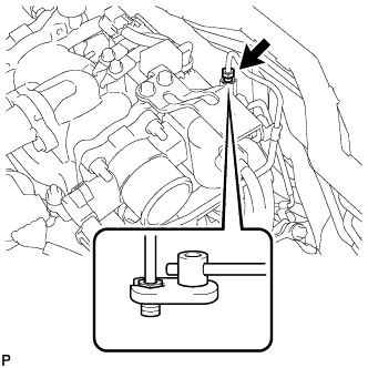
DISCONNECT NO. 2 ENGINE WIRE
-
Remove the 3 bolts and using a clip remover, detach the 2 wire harness clamps, and then disconnect the No. 2 engine wire.
-
-
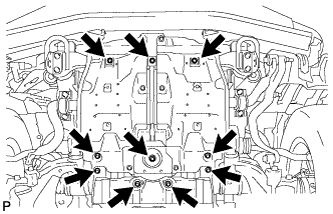
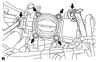
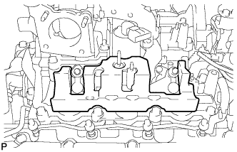
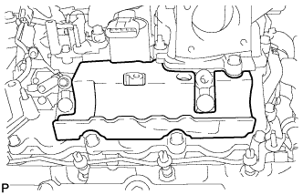
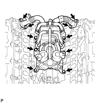
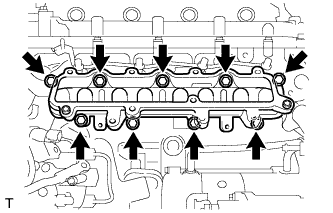
REMOVE NO. 3 INTAKE MANIFOLD
-
Remove the 16 bolts, No. 3 intake manifold and 2 gaskets.
-
-
REMOVE INTAKE MANIFOLD INSULATOR (w/ EGR System)
-
REMOVE EGR PIPE INSULATOR (w/ EGR System)
-
Remove the 2 bolts and EGR pipe insulator.
-
-
REMOVE EGR VALVE ASSEMBLY WITH EGR COOLER (w/ EGR System)
-
Remove the 10 bolts, EGR valve with EGR cooler and 2 gaskets.
-
Disconnect the No. 5 water by-pass hose from the water by-pass outlet.
-
-
REMOVE EGR COOLER INSULATOR (w/ EGR System)
-
REMOVE NO. 3 NOZZLE LEAKAGE PIPE (w/o DPF)
-
Disconnect the No. 1 fuel hose from the fuel cooler.
-
Remove the union bolt, bolt, No. 3 nozzle leakage pipe and gasket.
Note
After removing the nozzle leakage pipe, to prevent dirt or foreign objects from entering the nozzle leakage pipe, cover the nozzle leakage pipe ends with plastic bags.
-
-
REMOVE NO. 4 NOZZLE LEAKAGE PIPE (w/o DPF)
-
Disconnect the No. 2 fuel hose from the fuel cooler.
-
Remove the union bolt, bolt, No. 4 nozzle leakage pipe and gasket.
Note
After removing the nozzle leakage pipe, to prevent dirt or foreign objects from entering the nozzle leakage pipe, cover the nozzle leakage pipe ends with plastic bags.
-
-
DISCONNECT NO. 6 WATER BY-PASS HOSE (w/o DPF)
-
REMOVE FUEL COOLER ASSEMBLY (w/o DPF)
-
Remove the 2 bolts and fuel cooler.
-
-
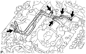
REMOVE FUEL TUBE SUB-ASSEMBLY (w/ DPF)
-
Disconnect the 3 fuel tube connectors Click here.
-
Detach the 3 clamps and remove the fuel tube.
-
-
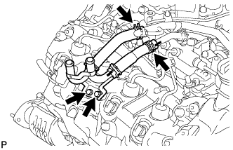
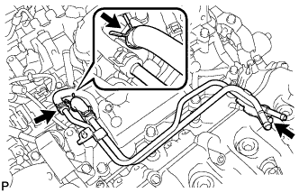
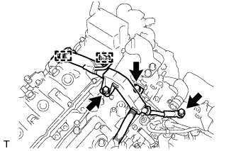
REMOVE NO. 1 WATER BY-PASS PIPE
-
Text in Illustration *A w/ DPF *B w/o DPF Remove the union bolt, bolt, No. 1 water by-pass pipe and gasket.
-
-
REMOVE FUEL HOSE BRACKET (w/ DPF)
-
Remove the bolt and fuel hose bracket.
-
-
REMOVE NO. 1 FUEL PIPE CLAMP (w/ DPF)
-
Text in Illustration *a RH Side *b LH Side Remove the 2 bolts and 2 No. 1 fuel pipe clamps.
-
-
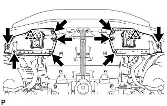
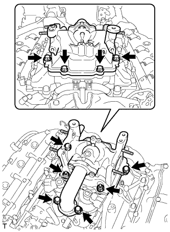
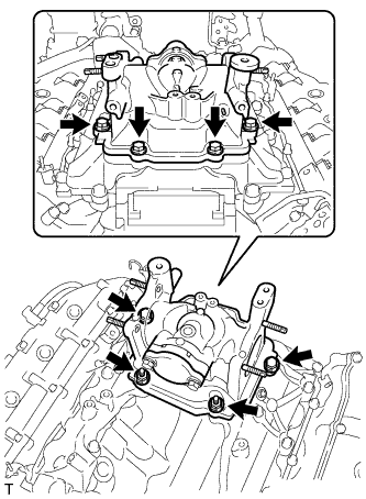
REMOVE NO. 1 INTAKE MANIFOLD
-
Remove the 9 bolts, No. 1 intake manifold and gasket.
-
-
REMOVE NO. 2 INTAKE MANIFOLD
-
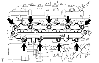
Remove the 9 bolts, No. 2 intake manifold and gasket.
-
-
REPLACE STUD BOLT
Tech Tips
If a stud bolt is deformed or its threads are damaged, replace it.
-
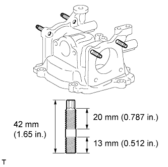
For Intake Pipe:
Using an E8 "TORX" wrench, replace the stud bolts.
- Torque:
- 6.0 N*m { 61 kgf*cm, 53 in.*lbf }
-
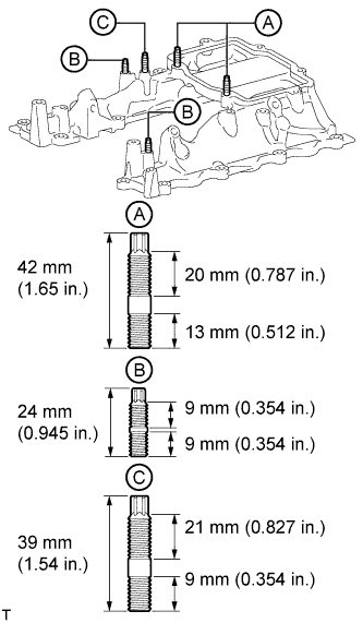
For No. 3 Intake Manifold:
-
Using an E8 "TORX" wrench, replace the stud bolts labeled A.
- Torque:
- 6.0 N*m { 61 kgf*cm, 53 in.*lbf }
-
Using an E6 "TORX" wrench, replace the stud bolts labeled B.
- Torque:
- 5.0 N*m { 51 kgf*cm, 44 in.*lbf }
-
Using an E6 "TORX" wrench, replace the stud bolt labeled C.
- Torque:
- 4.0 N*m { 41 kgf*cm, 35 in.*lbf }
-
-
-
REPLACE RING PIN
Tech Tips
It is not necessary to remove a ring pin unless it is being replaced.
-
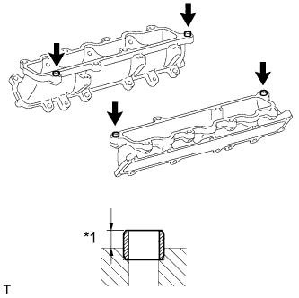
Text in Illustration *1 Protrusion height For No. 1 and No. 2 Intake Manifold:
Replace the ring pins.
Standard protrusion 4.4 to 5.6 mm (0.173 to 0.222 in.)
-