AIRBAG SYSTEM, Diagnostic DTC:B1661/44

| DTC Code | DTC Name |
|---|---|
| B1661/44 | Roll Over Cut Off Indicator Malfunction |
DESCRIPTION
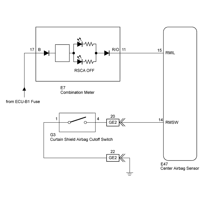
The curtain shield airbag cutoff switch is a mechanism that operates both the right and left sides of the curtain shield airbag and the front seat outer belt when the center airbag sensor detects a roll-over.
The RSCA OFF indicator is installed in the combination meter.
If the curtain shield airbag cutoff switch is operated, the indicator comes on to inform the drive that the roll-over detection system is not working.
The initial setting of the roll-over detection system is on. It automatically operates every time the ignition switch is turned to ON.
| DTC Code | DTC Detection Condition | Trouble Area |
|---|---|---|
| B1661/44 | When one of the following conditions is met:
|
|
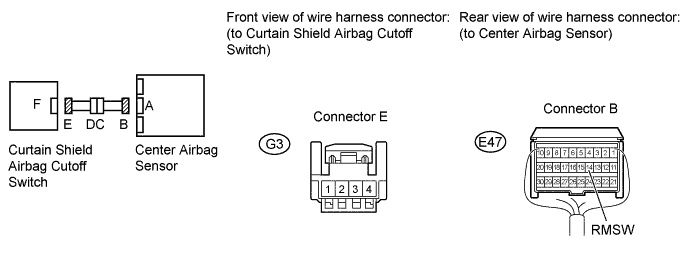
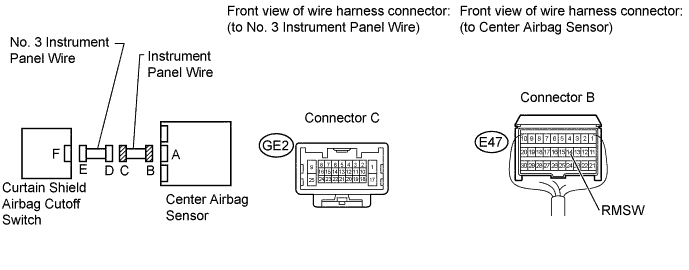
WIRING DIAGRAM
INSPECTION PROCEDURE
Note
-
After turning the ignition switch off, waiting time may be required before disconnecting the cable from the battery terminal. Therefore, make sure to read the disconnecting the cable from the battery terminal notice before proceeding with work Click here.
-
When disconnecting the cable, some systems need to be initialized after the cable is reconnected Click here.
PROCEDURE
-
CHECK COMBINATION METER (SOURCE VOLTAGE)
-
Turn the ignition switch off.
-
Disconnect the cable from the negative (-) battery terminal, and wait for at least 90 seconds.
-
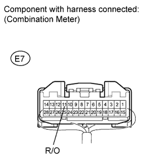
Remove the combination meter with the connector connected.
-
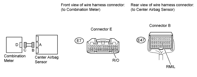
Disconnect the connector from the center airbag sensor.
-
Connect the cable to the negative (-) battery terminal, and wait for at least 2 seconds.
-
Turn the ignition switch to ON.
-
Measure the voltage according to the value(s) in the table below.
Standard Voltage Tester Connection Switch Condition Specified Condition E7-11 (R/O) - Body ground Ignition switch ON 11 to 14 V -
Turn the ignition switch off.
NG 
GO TO METER / GAUGE SYSTEM Click here
OK 
-
-
CHECK RSCA OFF INDICATOR CIRCUIT
-
Disconnect the cable from the negative (-) battery terminal, and wait for at least 90 seconds.
-
Disconnect the connector from the combination meter.
-
Connect the cable to the negative (-) battery terminal, and wait for at least 2 seconds.
-
Turn the ignition switch to ON.
-
Measure the voltage according to the value(s) in the table below.
Standard Voltage Tester Connection Switch Condition Specified Condition E7-11 (R/O) - Body ground Ignition switch ON Below 1 V -
Turn the ignition switch off.
-
Disconnect the cable from the negative (-) battery terminal, and wait for at least 90 seconds.
-
Measure the resistance according to the value(s) in the table below.
Standard Resistance Tester Connection Condition Specified Condition E7-11 (R/O) - E47-15 (RMIL) Always Below 1 Ω E7-11 (R/O) - Body ground Always 1 MΩ or higher
NG
REPLACE INSTRUMENT PANEL WIRE
OK
-
-
INSPECT CURTAIN SHIELD AIRBAG CUTOFF SWITCH
-
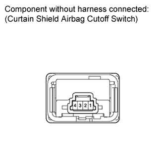
Remove the curtain shield airbag cutoff switch Click here.
-
Measure the resistance according to the value(s) in the table below.
Standard Resistance Tester Connection Switch Condition Specified Condition 4 - 1 Curtain shield airbag cutoff switch is in on position Below 1 Ω 4 - 1 Curtain shield airbag cutoff switch is in off position 1 MΩ or higher
NG
REPLACE CURTAIN SHIELD AIRBAG CUTOFF SWITCH Click here
OK
-
-
CHECK CURTAIN SHIELD AIRBAG CUTOFF SWITCH CIRCUIT
-
Connect the cable to the negative (-) battery terminal, and wait for at least 2 seconds.
-
Turn the ignition switch to ON.
-
Measure the voltage according to the value(s) in the table below.
Standard Voltage Tester Connection Switch Condition Specified Condition G3-4 - Body ground Ignition switch ON Below 1 V G3-1 - Body ground Ignition switch ON Below 1 V -
Turn the ignition switch off.
-
Disconnect the cable from the negative (-) battery terminal, and wait for at least 90 seconds.
-
Measure the resistance according to the value(s) in the table below.
Standard Resistance Tester Connection Condition Specified Condition E47-14 (RMSW) - G3-4 Always Below 1 Ω G3-4 - Body ground Always 1 MΩ or higher G3-1 - Body ground Always Below 1 Ω
NG 
CHECK INSTRUMENT PANEL WIRE (INSTRUMENT PANEL WIRE - NO. 3 INSTRUMENT PANEL WIRE AND BODY GROUND) Click here
OK 
REPLACE CENTER AIRBAG SENSOR ASSEMBLY Click here
-
-
CHECK INSTRUMENT PANEL WIRE (INSTRUMENT PANEL WIRE - NO. 3 INSTRUMENT PANEL WIRE AND BODY GROUND)
-
Disconnect the instrument panel wire connector from the No. 3 instrument panel wire.
-
Connect the cable to the negative (-) battery terminal, and wait for at least 2 seconds.
-
Turn the ignition switch to ON.
-
Measure the voltage according to the value(s) in the table below.
Standard Voltage Tester Connection Switch Condition Specified Condition GE2-20 - Body ground Ignition switch ON Below 1 V -
Turn the ignition switch off.
-
Disconnect the cable from the negative (-) battery terminal, and wait for at least 90 seconds.
-
Measure the resistance according to the value(s) in the table below.
Standard Resistance Tester Connection Condition Specified Condition E47-14 (RMSW) - GE2-20 Always Below 1 Ω GE2-20 - Body ground Always 1 MΩ or higher
NG
REPLACE INSTRUMENT PANEL WIRE
OK
REPLACE NO. 3 INSTRUMENT PANEL WIRE
-