AIRBAG SYSTEM, Diagnostic DTC:B1651/33

| DTC Code | DTC Name |
|---|---|
| B1651/33 | Manual Cut off Switch Trouble |
DESCRIPTION
Tech Tips
"Manual cut off switch" refers to the airbag cut-off switch.
-
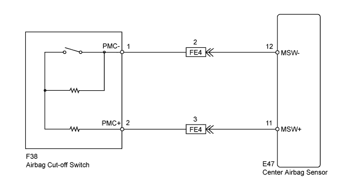
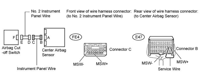
The airbag cut-off switch circuit consists of the center airbag sensor and the airbag cut-off switch.
The front passenger airbag can be optionally deactivated via this circuit by turning the airbag cut-off switch to the "OFF" position.
If the front passenger airbag is deactivated, the passenger airbag "OFF" indicator comes on to inform the passengers.
DTC B1651/33 is recorded when a malfunction is detected in the airbag cut-off switch circuit.
| DTC Code | DTC Detection Condition | Trouble Area |
|---|---|---|
| B1651/33 | When all the conditions below are met:
|
|
WIRING DIAGRAM
INSPECTION PROCEDURE
Note
-
After turning the ignition switch off, waiting time may be required before disconnecting the cable from the battery terminal. Therefore, make sure to read the disconnecting the cable from the battery terminal notice before proceeding with work Click here.
-
When disconnecting the cable, some systems need to be initialized after the cable is reconnected Click here.
Tech Tips
The E47-11 (MSW+) and E47-12 (MSW-) terminals in this circuit have an activation prevention mechanism. This mechanism can be used to check for an open circuit in the wire harness. In case of other checks (check for short, short to ground or short to B+), this mechanism should be released.
PROCEDURE
-
CHECK INSTRUMENT PANEL WIRE (CENTER AIRBAG SENSOR - AIRBAG CUT-OFF SWITCH)
-
Turn the ignition switch off.
-
Disconnect the cable from the negative (-) battery terminal, and wait for at least 90 seconds.
-
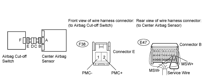
Disconnect the connectors from the center airbag sensor and airbag cut-off switch.
-
Connect the cable to the negative (-) battery terminal, and wait for at least 2 seconds.
-
Turn the ignition switch to ON.
-
Measure the voltage according to the value(s) in the table below.
Standard Voltage Tester Connection Switch Condition Specified Condition F38-2 (PMC+) - Body ground Ignition switch ON Below 1 V F38-1 (PMC-) - Body ground Ignition switch ON Below 1 V -
Turn the ignition switch off.
-
Disconnect the cable from the negative (-) battery terminal, and wait for at least 90 seconds.
-
Using a service wire, connector terminals 11 (MSW+) and 12 (MSW-) of connector B.
Note
Do not forcibly insert the service wire into the terminals of the connector when connecting a service wire.
-
Measure the resistance according to the value(s) in the table below.
Standard Resistance Tester Connection Condition Specified Condition F38-2 (PMC+) - F38-1 (PMC-) Always Below 1 Ω -
Disconnect a service wire from connector B.
-
Measure the resistance according to the value(s) in the table below.
Standard Resistance Tester Connection Condition Specified Condition F38-2 (PMC+) - F38-1 (PMC-) Always 1 MΩ or higher F38-2 (PMC+) - Body ground Always 1 MΩ or higher F38-1 (PMC-) - Body ground Always 1 MΩ or higher
NG 
CHECK INSTRUMENT PANEL WIRE (CENTER AIRBAG SENSOR - NO. 2 INSTRUMENT PANEL WIRE) Click here
OK 
-
-
INSPECT AIRBAG CUT-OFF SWITCH
-
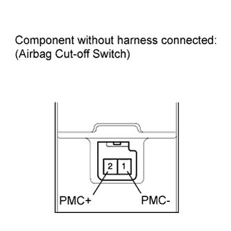
Remove the airbag cut-off switch Click here.
-
Measure the resistance according to the value(s) in the table below.
Standard Resistance Tester Connection Switch Condition Specified Condition 2 (PMC+) - 1 (PMC-) Cut off switch is in "ON" position (Front passenger side airbag is active) 360 to 440 Ω 2 (PMC+) - 1 (PMC-) Cut off switch is in "OFF" position (Front passenger side airbag is not active) 90 to 110 Ω
NG 
REPLACE AIRBAG CUT-OFF SWITCH Click here
OK
-
-
CHECK CENTER AIRBAG SENSOR
-
Connect the connectors to the center airbag sensor and the airbag cut-off switch.
-
Connect the cable to the negative (-) battery terminal, and wait for at least 2 seconds.
-
Turn the ignition switch to ON, and wait for at least 60 seconds.
-
Clear the DTCs stored in memory Click here.
-
Turn the ignition switch off.
-
Turn the ignition switch to ON, and wait for at least 60 seconds.
-
Check the DTCs Click here.
OK DTC B1651 is not output. Tech Tips
Codes other than DTC B1651 may be output at this time, but they are not related to this check.
NG
REPLACE CENTER AIRBAG SENSOR ASSEMBLY Click here
OK 
USE SIMULATION METHOD TO CHECK Click here
-
-
CHECK INSTRUMENT PANEL WIRE (CENTER AIRBAG SENSOR - NO. 2 INSTRUMENT PANEL WIRE)
-
Disconnect the instrument panel wire connector from the No. 2 instrument panel wire.
-
Connect the cable to the negative (-) battery terminal, and wait for at least 2 seconds.
-
Turn the ignition switch to ON.
-
Measure the voltage according to the value(s) in the table below.
Standard Voltage Tester Connection Switch Condition Specified Condition FE4-3 (MSW+) - Body ground Ignition switch ON Below 1 V FE4-2 (MSW-) - Body ground Ignition switch ON Below 1 V -
Turn the ignition switch off.
-
Disconnect the cable from the negative (-) battery terminal, and wait for at least 90 seconds.
-
Using a service wire, connector terminals 11 (MSW+) and 12 (MSW-) of connector B.
Note
Do not forcibly insert the service wire into the terminals of the connector when connecting a service wire.
-
Measure the resistance according to the value(s) in the table below.
Standard Resistance Tester Connection Condition Specified Condition FE4-3 (MSW+) - FE4-2 (MSW-) Always Below 1 Ω -
Disconnect the service wire from connector B.
-
Measure the resistance according to the value(s) in the table below.
Standard Resistance Tester Connection Condition Specified Condition FE4-3 (MSW+) - FE4-2 (MSW-) Always 1 MΩ or higher FE4-3 (MSW+) - Body ground Always 1 MΩ or higher FE4-2 (MSW-) - Body ground Always 1 MΩ or higher
NG
REPLACE INSTRUMENT PANEL WIRE
OK
REPLACE NO. 2 INSTRUMENT PANEL WIRE
-