-
Before performing these installation procedures, sufficiently clean and remove any foreign matter from the cylinder block, cylinder head, camshaft and other parts.
-
When replacing an injector (including interchanging injectors between cylinders), common rail, cylinder head, or intake manifold, replace the corresponding injection pipes with a new one.
-
Click here
CHECK INJECTOR COMPENSATION CODE
Note:
-
When a fuel injector is replaced, the new fuel injector compensation code must be input into the ECM. When the ECM is replaced, all of the existing fuel injector compensation codes must be input into the new ECM.
-
Fuel injector compensation codes are unique, 30 digit, alphanumeric values printed on the head portion of each fuel injector. If an incorrect fuel injector compensation code is input into the ECM, the engine assembly may rattle or engine idling may become rough. In addition, engine failure may occur and the life of the engine may be shortened.
-
After replacing fuel injector(s) with new one(s), input compensation code(s) of fuel injector(s) into ECM as follows:
Tip:
-
Each fuel injector has different fuel injection characteristics. In order to optimize the fuel injections, the ECM uses the compensation codes to balance the different fuel injections between each fuel injector.
-
When you first turn the ignition switch to ON after replacing the ECM or a fuel injector(s), DTC P1601 is set. This is to inform you that registration of a fuel injector compensation code(s) is/are required. Manually clear the DTC upon completion of the compensation code registration.
-
Input the compensation code(s), which is/are imprinted on the head portion(s) of the new fuel injector(s), into the intelligent tester.
-
Input the new compensation code(s) into the ECM using the tester.
-
Turn the tester off and turn the ignition switch off.
-
Wait for at least 30 seconds.
-
Turn the ignition switch to ON and turn the tester on.
-
Clear DTC P1601 stored in the ECM using the tester (Click here).
-
-
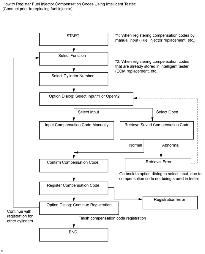
Register compensation code.
-
Connect the intelligent tester to the DLC3.
-
Turn the ignition switch to ON.
Note:Do not start the engine.
-
Turn the tester on.
-
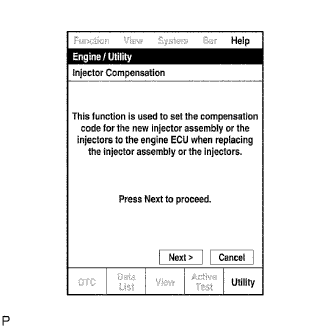
Enter the following menus: Powertrain / Engine / Utility / Injector Compensation.
-
Press Next.
-
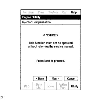
Press Next again to proceed.
-
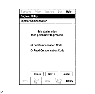
Select "Set Compensation Code".
-
Press Next.
-
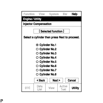
Select the number of the cylinder corresponding to the fuel injector compensation code that you want to read.
-
Press Next.
-
Register compensation code.
-
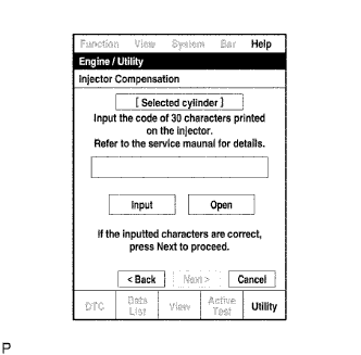
Press Input.
-
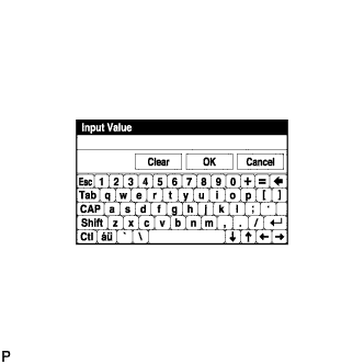
Manually input the cylinder compensation code using the keyboard on the tester screen. The code is a 30 digit, alphanumeric value printed on the injector head portion.
Tip:Each fuel injector compensation code is unique. The compensation code for each selected cylinder must be input into the tester correctly.
-
Confirm that the compensation code for the selected cylinder is correct, and then press OK.
-
-
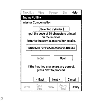
Check that the compensation code displayed on the screen is correct by comparing it with the 30 digit alphanumeric value on the head portion of the fuel injector.
Note:If an incorrect fuel injector compensation code is input into the ECM, the engine may rattle or engine idling may become rough. In addition, engine failure may occur and the life of the engine may be shortened.
Tip:
-
If a wrong compensation code is input or read, return to the Input Value screen by pressing Input.
-
The saving process may fail due to a problem with the wire harness or a bad connection with the DLC3. Check the wire harness and DLC3 connection. If no problem is found with either, the ECM may be malfunctioning. Check the ECM and repeat this operation.
-
-
Press Next to register the compensation code in the ECM.
Tip:
-
If the registration process fails, the compensation code may be incorrect. Check the compensation code again.
-
If the input compensation code fails to register even though it is input correctly, there may be a problem with the wire harness or a bad connection with the DLC3. Check the wire harness and DLC3 connection. If no problem is found with either, the ECM may be malfunctioning. Check the ECM and restart this operation.
-
-
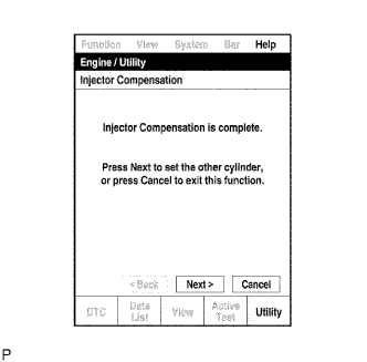
If you want to continue with other compensation code registrations, press Next. To finish the registration, press Cancel.
-
Turn the ignition switch off and then turn the tester off.
-
Wait for at least 30 seconds.
-
Turn the ignition switch to ON and then turn the tester on.
-
Clear DTC P1601 stored in the ECM using the tester (Click here).
-
-
- Click here
SELECT CYLINDER HEAD GASKET
-
Set the 2 crankshaft pulley set bolts to the crankshaft.
-
Clean the cylinder block with solvent.
-
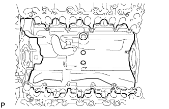
Inspect the protrusion for each cylinder.
-
Set the piston of the cylinder to be measured to slightly before TDC.
-
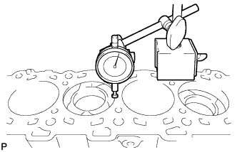
Place a dial indicator on the cylinder block, and set the measuring tip as shown in the illustration.
Note:Make sure that the dial indicator is at a right angle to the cylinder block top surface.
-
Set the dial indicator at 0 mm (0 in.).
Tip:Make sure that the measuring tip is flat against the cylinder block surface and piston head when taking the measurements.
-
Find where the piston head protrudes most by slowly turning the crankshaft clockwise and counterclockwise.
-
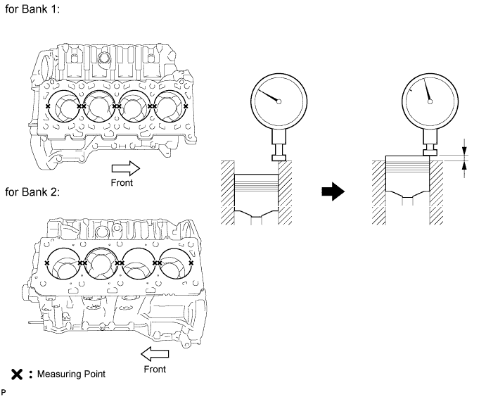
Measure the piston protrusion value of each cylinder at 2 places as shown in the illustration below, making a total of 8 measurements.
Standard piston protrusion 0.520 to 0.780 mm (0.0205 to 0.0307 in.) If the protrusion is not as specified, remove and reinstall the piston and connecting rod.
-
-
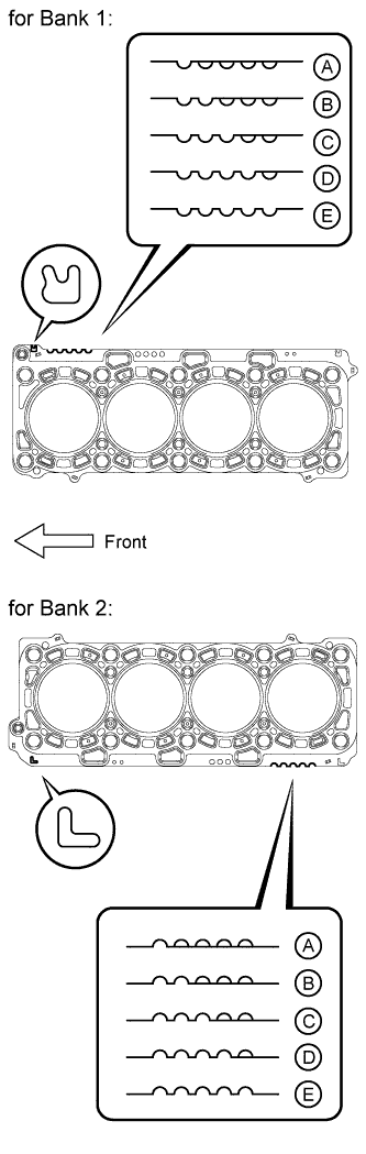
Select a new cylinder head gasket.
Tip:Cylinder head gaskets are marked A, B, C, D or E accordingly.
New Installed Cylinder Head Gasket Thickness Item Cutout Specified Condition* A 1 1.20 to 1.30 mm (0.0472 to 0.0512 in.) B 2 1.25 to 1.35 mm (0.0492 to 0.0394 in.) C 3 1.30 to 1.40 mm (0.0512 to 0.0551 in.) D 4 1.35 to 1.45 mm (0.0531 to 0.0571 in.) E 5 1.40 to 1.50 mm (0.0551 to 0.0591 in.) Tip:*: The specified condition indicates the thickness of the gasket after tightening the cylinder head.
-
Select the largest piston protrusion value from the measurements and then select a new appropriate gasket according to the table below.
Standard Piston Protrusion Item Specified Condition A 0.520 to 0.575 mm (0.0205 to 0.0226 in.) B 0.575 to 0.625 mm (0.0226 to 0.0246 in.) C 0.625 to 0.675 mm (0.0246 to 0.0266 in.) D 0.675 to 0.725 mm (0.0266 to 0.0285 in.) E 0.725 to 0.780 mm (0.0285 to 0.0307 in.)
-
-
- Click here
INSTALL NO. 2 CYLINDER HEAD GASKET
-
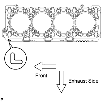
Remove any oil from the contact surface.
-
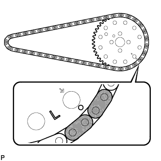
Place the cylinder head gasket on the cylinder block surface with the front face of the indicated mark "L" upward and facing the exhaust side.
-
- Click here
INSTALL NO. 1 CYLINDER HEAD GASKET
-
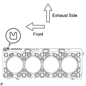
Remove any oil from the contact surface.
-
Place the cylinder head gasket on the cylinder block surface with the front face of the indicated mark "R" upward and facing the exhaust side.
-
- Click here
INSTALL CYLINDER HEAD SUB-ASSEMBLY LH
-
Place the cylinder head on the cylinder head gasket.
Note:Ensure that no oil is on the mounting surface of the cylinder head.
-
Inspect the cylinder head bolts (Click here).
-
Apply a light coat of engine oil to the threads and under the heads of the cylinder head bolts.
-
Step 1:
-
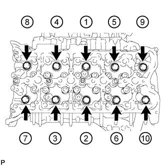
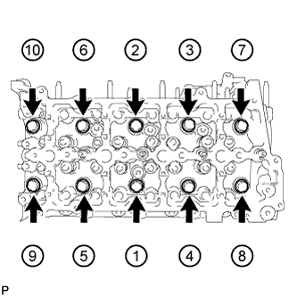
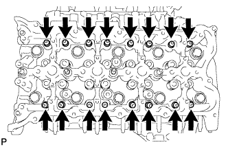
Install and uniformly tighten the 10 cylinder head bolts with the spacers in several steps, in the sequence shown in the illustration.
80 N*m 816 kgf*cm 59 ft.*lbf Tip:
-
The cylinder head bolts are tightened in 4 progressive steps.
-
If a cylinder head bolt is broken or deformed, replace it.
-
-
-
Step 2:
-
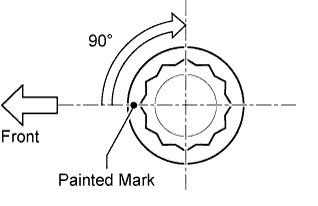
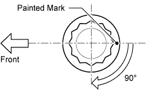
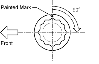
Mark the cylinder head bolt heads with paint as shown in the illustration.
-
Tighten the cylinder head bolts 90° in the sequence shown in step 1.
-
-
Step 3:
-
Tighten the cylinder head bolts another 90° in the sequence shown in step 1.
-
-
Step 4:
-
Tighten the cylinder head bolts by an additional 90° in the sequence shown in step 1.
-
-
Check that the painted marks are now facing the exhaust port side.
-
- Click here
INSTALL CYLINDER HEAD SUB-ASSEMBLY RH
-
Place the cylinder head on the cylinder head gasket.
Note:Ensure that no oil is on the mounting surface of the cylinder head.
-
Inspect the cylinder head bolts (Click here).
-
Apply a light coat of engine oil to the threads and under the heads of the cylinder head bolts.
-
Step 1:
-
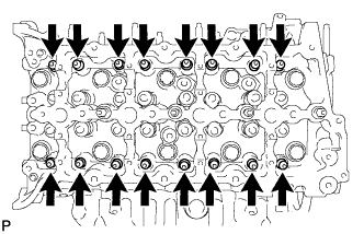
Install and uniformly tighten the 10 cylinder head bolts with the spacers in several steps, in the sequence shown in the illustration.
80 N*m 816 kgf*cm 59 ft.*lbf Tip:
-
The cylinder head bolts are tightened in 4 progressive steps.
-
If a cylinder head bolt is broken or deformed, replace it.
-
-
-
Step 2:
-
Mark the cylinder head bolt heads with paint as shown in the illustration.
-
Tighten the cylinder head bolts 90° in the sequence shown in step 1.
-
-
Step 3:
-
Tighten the cylinder head bolts another 90° in the sequence shown in step 1.
-
-
Step 4:
-
Tighten the cylinder head bolts by an additional 90° in the sequence shown in step 1.
-
-
Check that the painted marks are now facing the intake port side.
-
- Click here
SET NO. 1 CYLINDER TO 45° BEFORE TDC
-
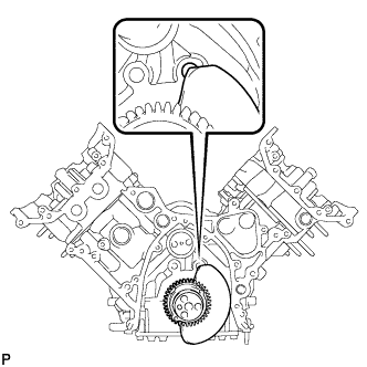
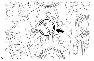
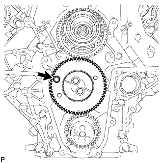
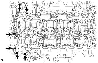
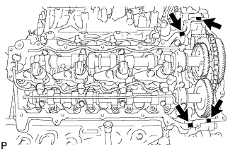
Using a bar, turn the crankshaft counterclockwise until the No. 1 cylinder is at a position 45° before TDC.
Note:Do not turn the crankshaft again until after the timing gear is installed.
Tip:The No. 1 cylinder is at a position 45° before TDC if the crankshaft counterweight is overlapping the cylinder block hole as shown in the illustration.
-
Remove the 2 crankshaft pulley set bolts.
-
- Click here
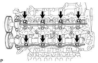
INSTALL NO. 2 VALVE LASH ADJUSTER ASSEMBLY
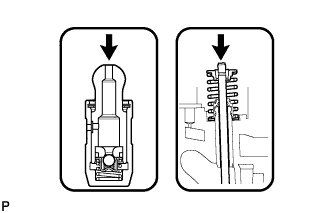
Note:Be sure to inspect the valve lash adjuster before installing it (Click here).
-
Install the 16 No. 2 valve lash adjusters to the cylinder head.
Tip:Install the lash adjuster at the same place it was removed from.
-
- Click here
INSTALL NO. 1 VALVE LASH ADJUSTER ASSEMBLY
Note:Be sure to inspect the valve lash adjuster before installing it (Click here).
-
Install the 16 No. 1 valve lash adjusters to the cylinder head.
Tip:Install the lash adjuster at the same place it was removed from.
-
- Click here
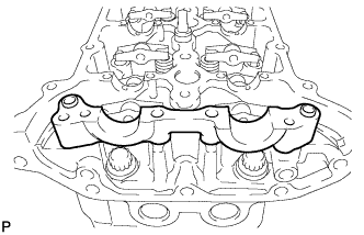
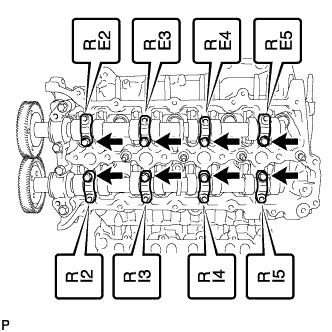
INSTALL NO. 2 VALVE ROCKER ARM
-
Apply engine oil to the lash adjuster tips and valve stem ends.
-
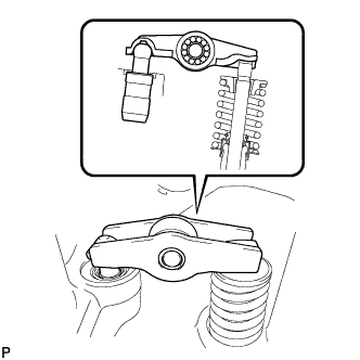
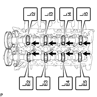
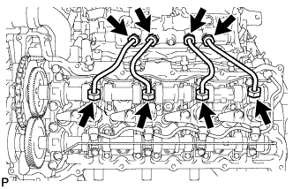
Install the 16 No. 2 valve rocker arms as shown in the illustration.
Tip:Install the valve rocker arm at the same place it was removed from.
-
- Click here
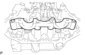
INSTALL NO. 1 VALVE ROCKER ARM
-
Apply engine oil to the lash adjuster tips and valve stem ends.
-
Install the 16 No. 1 valve rocker arms as shown in the illustration.
Tip:
Install the valve rocker arm at the same place it was removed from.
-
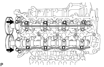
- Click here
INSTALL NO. 5 CAMSHAFT BEARING CAP
-
Align the camshaft bearing cap and the ring pins of the cylinder head, and install the cap.
-
- Click here
INSTALL NO. 2 CAMSHAFT BEARING CAP
-
Align the camshaft bearing cap and the ring pins of the cylinder head, and install the cap.
-
- Click here
INSTALL NO. 3 AND NO. 4 CAMSHAFTS
-
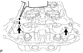
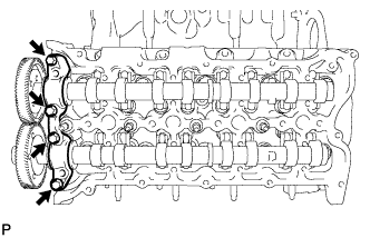
Add more than 19 cc (1.16 cu. in.) of engine oil into the cylinder head side oil holes.
-
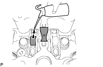
Apply engine oil to the rollers of the valve rocker arms and the camshaft housing of the cylinder head.
-
Install the camshafts.
-
Apply engine oil to the camshaft journals, lobes, thrust portion and gears.
-
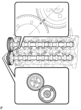
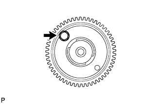
Align the timing marks (1 dot mark) on the back side of the No. 3 and No. 4 camshaft timing gears as shown in the illustration.
-
Place the camshafts into the cylinder head.
Note:
Before and after setting the camshafts, firmly set the rocker arms to the lash adjusters.
-
-
Install the No. 4 camshaft bearing cap.
-
Align the No. 4 camshaft bearing cap and the ring pins of the No. 5 camshaft bearing cap.
-
Temporarily install the 4 bolts by hand.
-
-
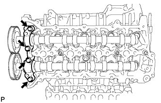
Install the No. 3 camshaft bearing caps.
-
Confirm the marks and numbers on the camshaft bearing caps and place them in their proper position and direction.
-
Temporarily install the 8 bolts, which are not installed with the oil feed pipe, by hand.
-
-
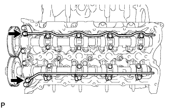
Temporarily install the No. 3 and No. 4 camshaft oil feed pipes with the 8 bolts by hand.
Note:If even one of the pipe bolt holes does not match its camshaft bearing cap bolt hole, replace the camshaft oil feed pipe.
Tip:The pipe is bent on the intake side, and straight on the exhaust side.
-
Temporarily install the 2 union bolts by hand.
-
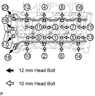
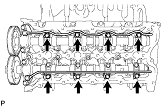
Uniformly tighten the 20 bolts in several steps in the order shown in the illustration.
for 12 mm head bolt of No. 4 camshaft bearing cap 21 N*m 214 kgf*cm 15 ft.*lbf for 10 mm head bolt of No. 3 camshaft bearing cap 10 N*m 102 kgf*cm 7 ft.*lbf -
Tighten the 2 union bolts.
17 N*m 173 kgf*cm 13 ft.*lbf -
Remove the bolt from the No. 4 camshaft timing gear.
Note:Do not drop the bolt into the engine.
-
- Click here
INSTALL NO. 1 AND NO. 2 CAMSHAFT
-
Add more than 19 cc (1.16 cu. in.) of engine oil into the cylinder head side oil holes.
-
Apply engine oil to the rollers of the valve rocker arms and the camshaft housing of the cylinder head.
-

Install the camshafts.
-
Apply engine oil to the camshaft journals, lobes, thrust portion and gears.
-
Align the timing marks (2 dot marks) on the back side of the No. 1 and No. 2 camshaft timing gears as shown in the illustration.
-
Place the camshafts into the cylinder head.
Note:
Before and after setting the camshafts, firmly set the rocker arms to the lash adjusters.
-
-
Install the No. 1 camshaft bearing cap.
-
Align the No. 1 camshaft bearing cap and the ring pins of the No. 2 camshaft bearing cap.
-
Temporarily install the 4 bolts by hand.
-
-
Install the No. 3 camshaft bearing caps.
-
Confirm the marks and numbers on the camshaft bearing caps and place them in their proper position and direction.
-
Temporarily install the 8 bolts, which are not installed with the oil feed pipe, by hand.
-
-
Temporarily install the No. 1 and No. 2 camshaft oil feed pipes with the 8 bolts by hand.
Note:If even one of the pipe bolt holes does not match its camshaft bearing cap bolt hole, replace the camshaft oil feed pipe.
Tip:The pipe is bent on the intake side, and straight on the exhaust side.
-
Temporarily install the 2 union bolts by hand.
-

Uniformly tighten the 20 bolts in several steps in the order shown in the illustration.
for 12 mm head bolt of No. 1 camshaft bearing cap 21 N*m 214 kgf*cm 15 ft.*lbf for 10 mm head bolt of No. 3 camshaft bearing cap 10 N*m 102 kgf*cm 7 ft.*lbf -
Tighten the 2 union bolts.
17 N*m 173 kgf*cm 13 ft.*lbf -
Remove the bolt from the No. 1 camshaft timing gear.
Note:Do not drop the bolt into the engine.
-
- Click here
INSTALL TIMING GEAR CASE SUB-ASSEMBLY
Note: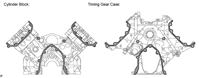
When the contact surfaces shown below are wet, wipe them with an oil-free cloth before applying seal packing.
-
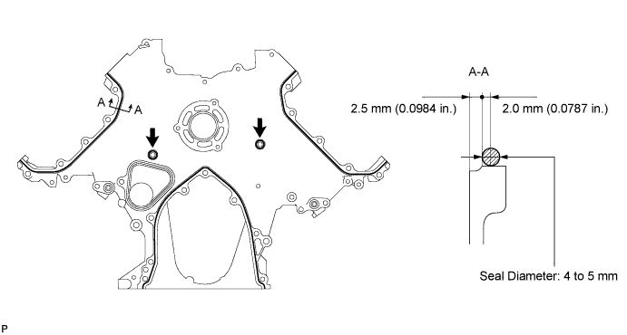
Apply seal packing to the timing gear case as shown in the following illustration.
Standard seal diameter 4 to 5 mm (0.157 to 0.197 in.) Seal packing Toyota Genuine Seal Packing Black, Three Bond 1207B or equivalent Note:
-
After applying seal packing, align the timing gear case with the engine within 3 minutes and tighten the bolts and nuts within 15 minutes.
-
Apply the seal packing in a continuous line.
Tip:
-
The FIPG line is shown below.
-
Apply packing to the 5 seal surface areas.
-
-
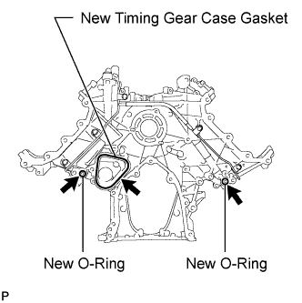
Install a new timing gear case gasket.
-
Apply engine oil to 2 new O-rings and install them to the timing gear case.
-
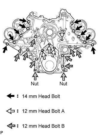
Install the timing gear case with the 22 bolts and 2 nuts.
for 14 mm head bolt (case is dry) 46 N*m 469 kgf*cm 34 ft.*lbf for 14 mm head bolt (case is wet) 42 N*m 428 kgf*cm 31 ft.*lbf for 12 mm head bolt A and B 29 N*m 296 kgf*cm 21 ft.*lbf for nut 29 N*m 296 kgf*cm 21 ft.*lbf Note:
-
The case is "dry" when there is absolutely no engine oil on the 14 mm head bolts and cylinder head bolt holes.
-
The case is "wet" when there is engine oil on the 14 mm head bolts and cylinder head bolt holes.
Table 1. Bolt Length Item Quantity Length A 4 20 mm (0.787 in.) B 8 45 mm (1.77 in.) -
-
- Click here
INSTALL V-BANK SILENCER
-
Align the alignment areas of the V-bank silencer and cylinder block, and install the V-bank silencer.
Note:Verify that the V-bank silencer is below the top surface of the intake port of the cylinder head RH and LH.
-
- Click here
INSTALL FUEL SUPPLY PUMP ASSEMBLY
-
Using an 8 mm x 1.25 pitch tap, remove the adhesive from the timing gear case side bolt hole.
-
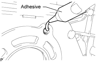
Apply adhesive to 2 or more threads of the timing gear case bolt hole.
Adhesive Toyota Genuine Adhesive 1344, Three Bond 1344 or equivalent -
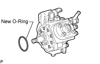
Apply engine oil to a new O-ring and install it to the supply pump.
-
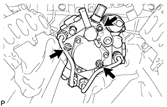
Install the supply pump to the timing gear case.
Note:When installing the supply pump, do not hold the fuel pipe to prevent fuel leaks.
-
Temporarily install the 2 nuts.
-
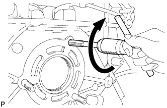
Using a 6 mm hexagon wrench, install the hexagon bolt, and then tighten the 2 nuts.
21 N*m 214 kgf*cm 15 ft.*lbf
-
-
- Click here
INSPECT RADIAL BALL BEARING
-
Turn the bearing, and check that the bearing moves smoothly and quietly.
If it moves roughly or noisily, replace the radial ball bearing.
-
- Click here
TEMPORARILY INSTALL FUEL SUPPLY PUMP DRIVE GEAR
-
Align the cutout of the supply pump drive gear and key of the supply pump, and temporarily install the nut.
-
- Click here
SET NO. 1 AND NO. 2 CAMSHAFTS TO TDC
-
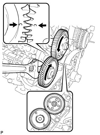
Using a wrench, turn the No. 1 camshaft and align the timing marks (1 dot mark) on the back side of the timing gears as shown in the illustration.
-
- Click here
INSTALL NO. 1 IDLE GEAR SHAFT
-
Apply engine oil to the contact surface of the idle gear shaft and the back side of the protrusion.
-
Install the idle gear shaft to the cylinder block.
-
- Click here
INSTALL IDLE GEAR ASSEMBLY
-
Temporarily install the 2 crankshaft pulley set bolts to the crankshaft.
-
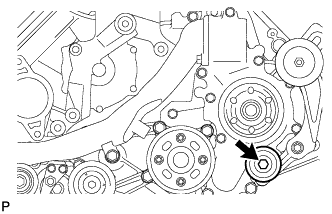
Using a bar, turn the crankshaft clockwise to the No. 1 cylinder TDC position.
-
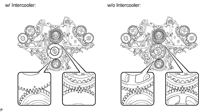
Align the timing marks of the supply pump drive gear and idle gear, and the timing marks of the crankshaft timing gear and idle gear as shown in the illustration.
-
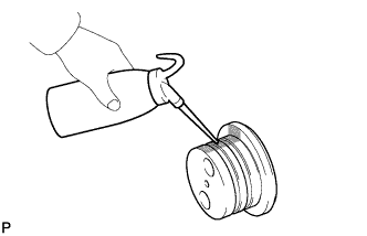
Apply engine oil to the idle gear thrust plate and gears.
-
Install the idle gear thrust plate with the 2 bolts.
47 N*m 479 kgf*cm 35 ft.*lbf -
w/ Intercooler:
Remove the service bolt.
-
- Click here
TIGHTEN FUEL SUPPLY PUMP DRIVE GEAR NUT
-
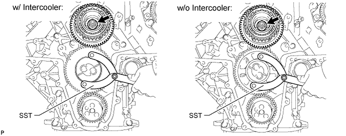
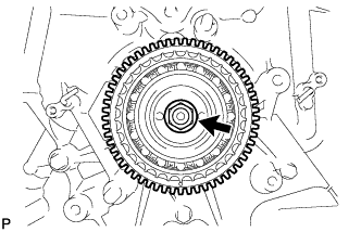
Using SST, hold the idle gear and tighten the nut.
09960-10010 09962-01000 09963-00700 68 N*m 693 kgf*cm 50 ft.*lbf
-
- Click here
CHECK NO. 1 CYLINDER TO TDC/COMPRESSION
-
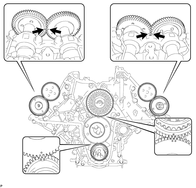
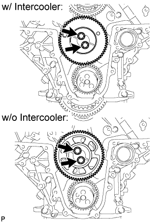
Check that the timing marks of the following pairs of parts are aligned: 1) supply pump drive gear and idle gear: 2) crankshaft timing gear and idle gear: 3) RH and LH camshaft timing gears.
-
- Click here
INSTALL NO. 2 CAMSHAFT TIMING SPROCKET AND NO. 2 TIMING CHAIN
-
Align the 2 mark plates (yellow) on the No. 2 timing chain with the timing mark (1 dot mark) of the No. 2 camshaft timing sprocket as shown in the illustration.
-
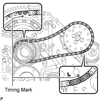
Align the No. 2 timing chain mark plate (yellow) with the supply pump drive gear timing mark, and temporarily install the No. 2 camshaft timing sprocket with the 4 bolts.
-
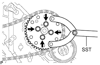
Using SST, hold the No. 2 camshaft timing sprocket, and tighten the 4 bolts.
09960-10010 09962-01000 09963-01000 25 N*m 250 kgf*cm 18 ft.*lbf
-
- Click here
INSTALL NO. 1 CAMSHAFT TIMING SPROCKET AND NO. 1 TIMING CHAIN
-
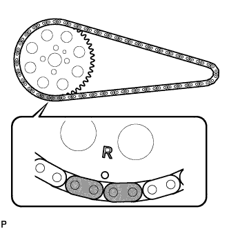
Align the 2 mark plates (yellow) on the No. 1 timing chain with the timing mark (1 dot mark) of the No. 1 camshaft timing sprocket as shown in the illustration.
-

Align the No. 1 timing chain mark plate (yellow) with the supply pump drive gear timing mark, and temporarily install the No. 1 camshaft timing sprocket.
-
- Click here
INSTALL PUMP DRIVE SHAFT GEAR
-

Temporarily install the pump drive shaft gear with the 4 bolts.
-
Using SST, hold the pump drive shaft gear and tighten the 4 bolts.
09960-10010 09962-01000 09963-01000 25 N*m 250 kgf*cm 18 ft.*lbf
-
- Click here
INSTALL NO. 2 CHAIN VIBRATION DAMPER
-
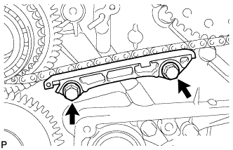
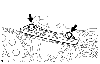
Install the No. 2 chain vibration damper with the 2 bolts.
21 N*m 214 kgf*cm 15 ft.*lbf
-
-
Click here
INSTALL NO. 2 CHAIN TENSIONER SLIPPER
- Click here
INSTALL NO. 2 CHAIN TENSIONER ASSEMBLY
-
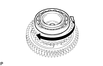
Move the stopper plate clockwise to release the lock, and push the plunger into the tensioner.
-
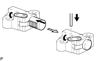
Move the stopper plate counterclockwise to set the lock, and insert a hexagon wrench into the stopper plate hole.
-
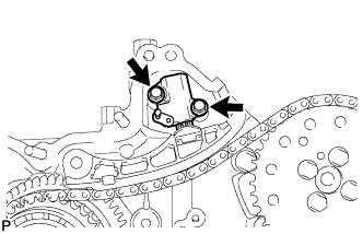
Install the No. 2 chain tensioner with the 2 bolts.
10 N*m 102 kgf*cm 7 ft.*lbf -
Remove the hexagon wrench.
-
- Click here
INSTALL NO. 1 CHAIN VIBRATION DAMPER
-
Install the No. 1 chain vibration damper with the 2 bolts.
21 N*m 214 kgf*cm 15 ft.*lbf
-
-
Click here
INSTALL NO. 1 CHAIN TENSIONER SLIPPER
- Click here
INSTALL NO. 1 CHAIN TENSIONER ASSEMBLY
-
Move the stopper plate clockwise to release the lock, and push the plunger into the tensioner.
-
Move the stopper plate counterclockwise to set the lock, and insert a hexagon wrench into the stopper plate hole.
-

Install the No. 1 chain tensioner with the 2 bolts.
10 N*m 102 kgf*cm 7 ft.*lbf -
Remove the hexagon wrench.
-
- Click here
INSTALL NO. 1 CRANKSHAFT POSITION SENSOR PLATE
-
Remove the adhesive from the threads of the screws and the bolt holes of the crankshaft.
-
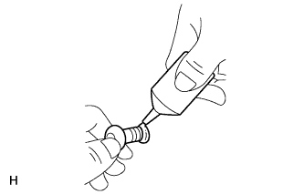
Apply adhesive to 2 or 3 threads of the 2 screws.
Adhesive Toyota Genuine Adhesive 1344, Three Bond 1344 or equivalent -
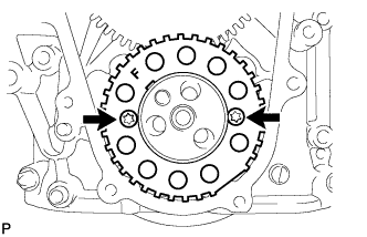
Using a T30 "TORX" wrench, install the No. 1 crankshaft position sensor plate with the 2 screws.
10 N*m 102 kgf*cm 7 ft.*lbf Note:Make sure the "F" mark on the plate is facing towards the front side of the engine.
-
- Click here
CHECK NO. 1 CYLINDER TO TDC/COMPRESSION
-
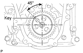
Temporarily install the 2 crankshaft pulley set bolts to the crankshaft.
-
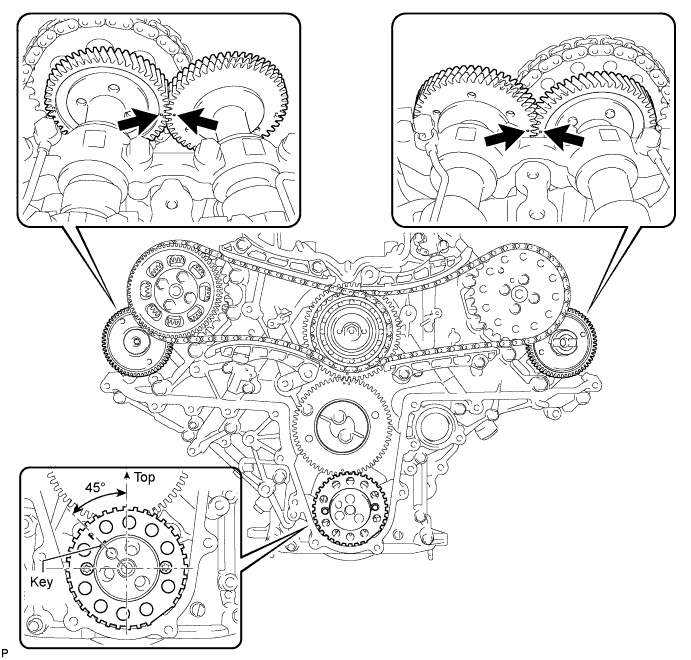
Rotate the crankshaft 2 revolutions or more so that the crankshaft key is 45° counterclockwise from the top. Check that the timing marks (1 dot mark each) of the RH and LH camshaft timing gears align. If not as specified, turn the crankshaft 1 revolution (360°) and align the timing marks. If the timing marks are deviated, reinstall the chain and camshaft.
-
Remove the 2 crankshaft pulley set bolts.
-
- Click here
INSTALL FRONT CRANKSHAFT OIL SEAL
-
Place the timing chain cover on wooden blocks.
-
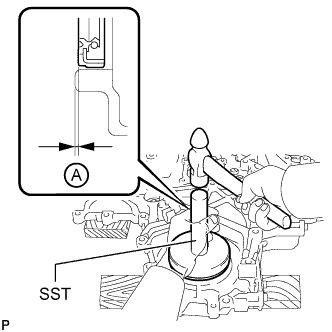
Using SST and a hammer, tap in a new oil seal as shown in the illustration.
09316-12010 09950-70010 09951-07100 09950-60020 09951-00890 Standard depth A 0.6 to 1.4 mm (0.0236 to 0.0551 in.)
-
- Click here
INSTALL TIMING CHAIN COVER SUB-ASSEMBLY
Note: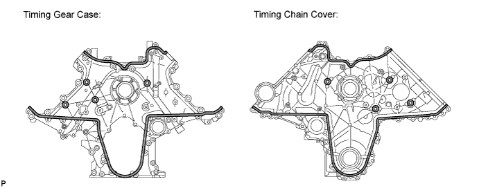
When the contact surfaces shown below are wet, wipe them with an oil-free cloth before applying seal packing.
-
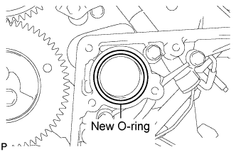
Install a new O-ring to the timing gear case.
-
Apply seal packing to the timing chain cover as shown in the following illustration.
Standard seal diameter 4 to 5 mm (0.157 to 0.197 in.) Seal packing Toyota Genuine Seal Packing Black, Three Bond 1207B or equivalent Note:
-
After applying seal packing, align the timing chain cover with the timing gear case within 3 minutes and tighten the bolts and nuts within 15 minutes.
-
Apply the seal packing in a continuous line.
-
Make sure the seal packing does not become thinner than 4 mm (0.157 in.) at the areas labeled "B" in the illustration below.
Tip:
-
The FIPG line is shown below.
-
Apply packing to the 6 seal surface areas.
-
-
Apply engine oil to the lip of the oil seal.
-
Align and install the timing chain cover to the timing gear case knock pin and supply pump bearing.
Note:Make sure that the lip of the oil seal is properly installed.
25 N*m 250 kgf*cm 18 ft.*lbf Tip: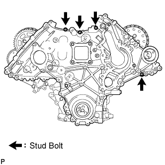
If the stud bolts are loose, tighten them before performing this procedure.
-
Using an E7 "TORX" wrench, tighten the stud bolts.
6.0 N*m 61 kgf*cm 53 in.*lbf
-
-
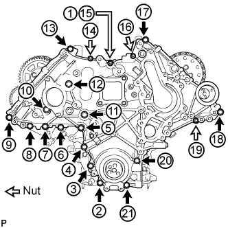
Install and uniformly tighten the 16 bolts and 4 nuts in the order shown in the illustration.
-
- Click here
TEMPORARILY INSTALL INTAKE MANIFOLD
-
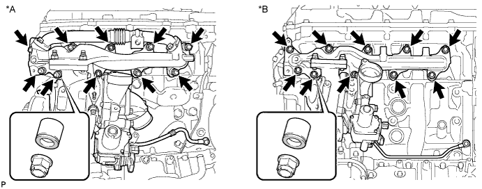
Install the gasket and temporarily install the No. 2 intake manifold with the 9 bolts.
-
Install the gasket and temporarily install the No. 1 intake manifold with the 9 bolts.
-
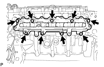
Install the 2 gaskets and temporarily install the No. 3 intake manifold with the 16 bolts.
Table 2. Bolt Length Item Length Bolt A 70 mm (2.76 in.) Bolt B 25 mm (0.984 in.)
-
- Click here
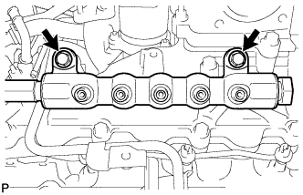
TEMPORARILY INSTALL COMMON RAIL ASSEMBLY RH
-
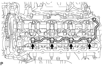
Install the common rail with the 2 bolts.
21 N*m 214 kgf*cm 15 ft.*lbf
-
- Click here
TEMPORARILY INSTALL COMMON RAIL ASSEMBLY LH
-
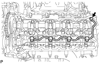
Install the common rail with the 2 bolts.
21 N*m 214 kgf*cm 15 ft.*lbf
-
- Click here
INSTALL FUEL INJECTOR RH
Note:Be sure to install the injector, holder clamp and bolt to their original positions.
-
Install 4 new injection nozzle seats to the cylinder head.
-
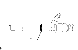
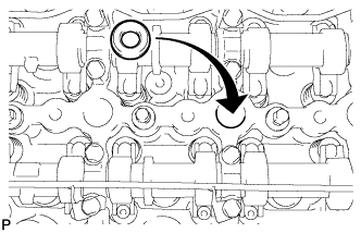
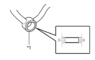
Apply a light coat of clean engine oil to 4 new O-rings.
Table 3. Text in Illustration *1 New O-Ring -
Install the O-rings to each injector as shown in the illustration.
-
Insert the 4 injectors into the cylinder head.
Note:
-
Insert the injector until it touches the nozzle seat surface.
-
After installing the injector to the cylinder head, the O-ring may prevent the injector from fully seating. If so, pull out the injector and reinstall it.
-
Always return an injector to the same place it was removed from.
-
-
For an injector that has been replaced with a new injector, register the injector compensation code.
-
Temporarily install 4 new washers and the 4 nozzle clamps with the 4 clamp bolts.
Note:
-
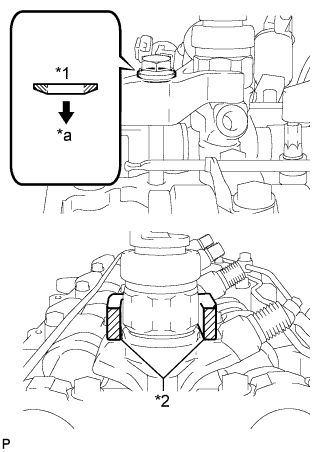
The fork portion of the nozzle holder clamp must be set on the injector.
-
Before tightening the bolts, check that the nozzle holder clamp is set properly.
-
To tighten the clamp bolts, first tighten them by hand until they cannot be turned further. Then, tighten the bolts to the specified torque in a later step.
-
When tightening the bolts, be careful not to tilt the bolt and clamp.
-
Do not reuse the washer.
Table 4. Text in Illustration *1 Washer *2 Nozzle Holder Clamp *a Downward -
-
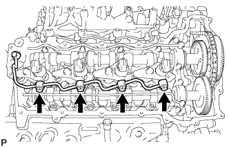
Temporarily install 4 new injection pipes to the common rail and injector.
-
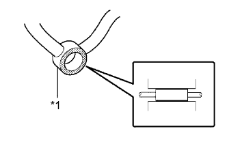
Check the nozzle leakage pipe. Check that there are no scratches or dents on the 5 union seal surfaces. If scratches or dents are present, replace the nozzle leakage pipe.
Table 5. Text in Illustration *1 Nozzle Leakage Pipe -
Set the leakage pipe and 5 new gaskets in place.
-
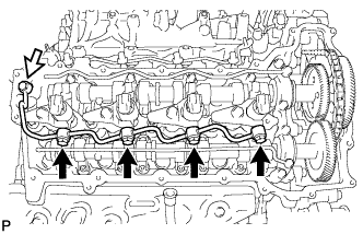
Temporarily install the leakage pipe with the 4 hollow screws and union bolt.
Table 6. Text in Illustration 
Union Bolt Tip:To position the injectors, loosely tighten the 4 hollow screws and union bolt.
-
Tighten the 4 holder clamp bolts.
25 N*m 255 kgf*cm 18 ft.*lbf -
Remove the 4 injection pipes.
-
Tighten the 4 hollow screws.
18 N*m 184 kgf*cm 13 ft.*lbf Note:If a hollow screw is accidentally tightened beyond the torque specification, it must be replaced together with the nozzle leakage pipe.
-
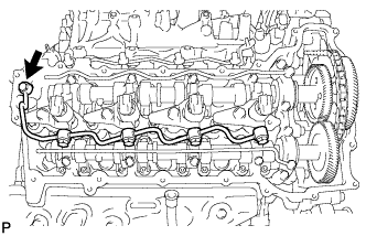
Tighten the union bolt.
21 N*m 214 kgf*cm 15 ft.*lbf Note:If the union bolt is accidentally tightened beyond the torque specification, it must be replaced together with the nozzle leakage pipe.
-
- Click here
INSTALL FUEL INJECTOR LH
Note:Be sure to install the injector, holder clamp and bolt to their original positions.
-
Install 4 new injection nozzle seats to the cylinder head.
-
Apply a light coat of clean engine oil to 4 new O-rings.
Table 7. Text in Illustration *1 New O-Ring -
Install the O-rings to each injector as shown in the illustration.
-
Insert the 4 injectors into the cylinder head.
Note:
-
Insert the injector until it touches the nozzle seat surface.
-
After installing the injector to the cylinder head, the O-ring may prevent the injector from fully seating. If so, pull out the injector and reinstall it.
-
Always return an injector to the same place it was removed from.
-
-
For an injector that has been replaced with a new injector, register the injector compensation code.
-
Temporarily install 4 new washers and the 4 nozzle clamps with the 4 clamp bolts.
Note:
-
The fork portion of the nozzle holder clamp must be set on the injector.
-
Before tightening the bolts, check that the nozzle holder clamp is set properly.
-
To tighten the clamp bolts, first tighten them by hand until they cannot be turned further. Then, tighten the bolts to the specified torque in a later step.
-
When tightening the bolts, be careful not to tilt the bolt and clamp.
-
Do not reuse the washer.
Table 8. Text in Illustration *1 Washer *2 Nozzle Holder Clamp *a Downward -
-
Temporarily install the common rail LH with the 2 bolts.
-
Temporarily install 4 new injection pipes to the common rail and injector.
-
Check the nozzle leakage pipe. Check that there are no scratches or dents on the 5 union seal surfaces. If scratches or dents are present, replace the nozzle leakage pipe.
Table 9. Text in Illustration *1 Nozzle Leakage Pipe -
Set the leakage pipe and 5 new gaskets in place.
-

Temporarily install the leakage pipe with the 4 hollow screws and union bolt.
Table 10. Text in Illustration Union Bolt Tip:To position the injectors, loosely tighten the 4 hollow screws and union bolt.
-
Tighten the 4 holder clamp bolts.
25 N*m 255 kgf*cm 18 ft.*lbf -
Remove the 4 injection pipes.
-
Remove the 2 bolts and common rail LH.
-
Tighten the 4 hollow screws.
18 N*m 184 kgf*cm 13 ft.*lbf Note:If a hollow screw is accidentally tightened beyond the torque specification, it must be replaced together with the nozzle leakage pipe.
-
Tighten the union bolt.
21 N*m 214 kgf*cm 15 ft.*lbf Note:If the union bolt is accidentally tightened beyond the torque specification, it must be replaced together with the nozzle leakage pipe.
-
- Click here
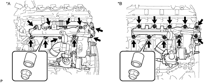
REMOVE COMMON RAIL ASSEMBLY RH
-
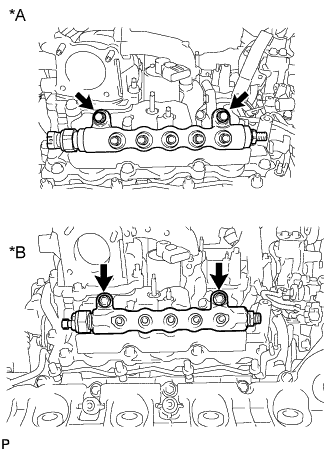
Remove the 2 bolts and common rail.
Table 11. Text in Illustration *A w/ DPF *B w/o DPF Note:Do not remove the fuel pressure sensor from the common rail. If it is removed, replace the common rail.
-
- Click here
REMOVE COMMON RAIL ASSEMBLY LH
-
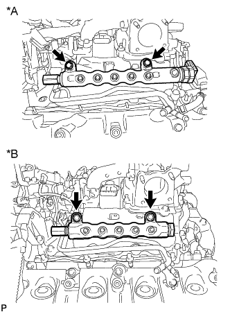
Remove the 2 bolts and common rail.
Table 12. Text in Illustration *A w/ DPF *B w/o DPF Note:
-
Do not remove the fuel pressure limiter from the common rail. If it is removed, replace the common rail.
-
w/ DPF:
Do not remove the pressure discharge valve from the common rail. If it is removed, replace the common rail.
-
-
- Click here
REMOVE INTAKE MANIFOLD
-
Remove the 16 bolts, 2 gaskets and intake manifold.
-
Remove the 9 bolts, No. 1 intake manifold and gasket.
-
Remove the 9 bolts, No. 2 intake manifold and gasket.
-
- Click here
INSTALL NOZZLE HOLDER GASKET LH
-
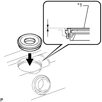
Press 4 new nozzle holder gaskets into the cylinder head cover LH.
Note:After installing the nozzle holder gasket, check that it does not protrude from the cylinder head cover.
Table 13. Text in Illustration *1 Nozzle Holder Gasket
-
- Click here
INSTALL CYLINDER HEAD COVER SUB-ASSEMBLY LH
-
Apply seal packing as shown in the illustration.
Seal packing Toyota Genuine Seal Packing Black, Three Bond 1207B or equivalent Table 14. Text in Illustration 
Seal Packing Note:
-
Remove any oil from the contact surface.
-
Install the cylinder head cover within 3 minutes and tighten the bolts within 15 minutes after applying seal packing.
-
Do not start the engine for at least 2 hours after the installation.
-
-
Install a new gasket to the cylinder head cover.
Note:Remove any oil from the contact surface.
-
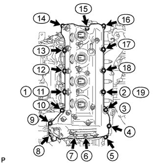
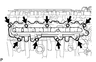
Temporarily install the cylinder head cover with the 17 bolts. Tighten the 17 bolts in the order shown in the illustration.
10 N*m 102 kgf*cm 7 ft.*lbf Tip:After tightening the bolts, check that the bolts at step 11 and 19 are tightened to the specified torque.
-
- Click here
INSTALL NOZZLE HOLDER SEAL LH
-
Press 4 new holder seals into the cylinder head cover LH.
-
- Click here
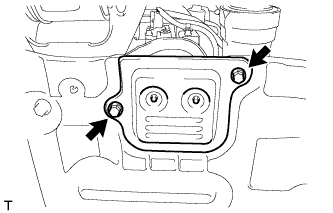
INSTALL OIL SEPARATOR ASSEMBLY
-
Install a new gasket to the oil separator.
Note:Remove any oil from the contact surface.
-
Install the oil separator with the 3 bolts.
10 N*m 102 kgf*cm 7 ft.*lbf
-
- Click here
INSTALL NOZZLE HOLDER GASKET RH
-
Press 4 new nozzle holder gaskets into the cylinder head cover RH.
Note:After installing the nozzle holder gasket, check that it does not protrude from the cylinder head cover.
Table 15. Text in Illustration *1 Nozzle Holder Gasket
-
- Click here
INSTALL CYLINDER HEAD COVER SUB-ASSEMBLY RH
-
Apply seal packing as shown in the illustration.
Seal packing Toyota Genuine Seal Packing Black, Three Bond 1207B or equivalent Table 16. Text in Illustration Seal Packing Note:
-
Remove any oil from the contact surface.
-
Install the cylinder head cover within 3 minutes and tighten the bolts within 15 minutes after applying seal packing.
-
Do not start the engine for at least 2 hours after the installation.
-
-
Install a new gasket to the cylinder head cover.
Note:Remove any oil from the contact surface.
-
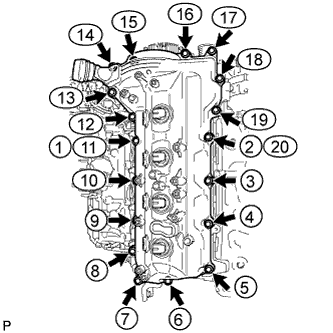
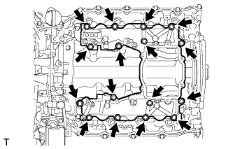
Temporarily install the cylinder head cover with the 18 bolts. Tighten the 18 bolts in the order shown in the illustration.
10 N*m 102 kgf*cm 7 ft.*lbf Tip:After tightening the bolts, check that the bolts at step 11 and 20 are tightened to the specified torque.
-
- Click here
INSTALL NOZZLE HOLDER SEAL RH
-
Press 4 new holder seals into the cylinder head cover RH.
-
- Click here
INSTALL CYLINDER HEAD COVER SILENCER LH (w/ Intercooler)
-
Install the cylinder head cover silencer with the 3 bolts.
5.0 N*m 51 kgf*cm 44 in.*lbf
-
- Click here
INSTALL CYLINDER HEAD COVER SILENCER RH (w/ Intercooler)
-
Install the cylinder head cover silencer with the 3 bolts.
5.0 N*m 51 kgf*cm 44 in.*lbf
-
- Click here
INSTALL VACUUM PUMP ASSEMBLY (w/ Intercooler)
-
Apply engine oil to 2 new O-rings.
-
Install the 2 O-rings to the vacuum pump.
-
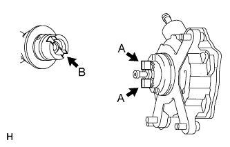
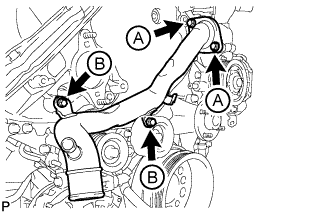
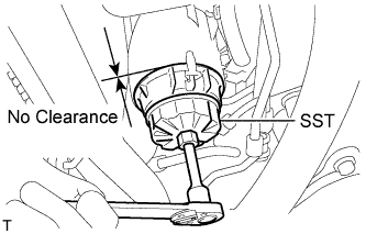
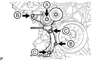
Install the vacuum pump so that the coupling teeth of the vacuum pump (labeled A) and the groove of the camshaft (labeled B) are aligned.
Note:Be careful not to damage the O-ring.
-
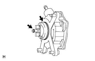
Install the vacuum pump with the 3 bolts.
21 N*m 214 kgf*cm 15 ft.*lbf Note:Confirm that the vacuum pump is not at an angle, and that there is no clearance between the fitting surfaces.
-
- Click here
INSTALL NO. 1 VACUUM TRANSMITTING PIPE SUB-ASSEMBLY
-
Install the vacuum transmitting pipe with the 3 bolts.
6.0 N*m 61 kgf*cm 53 in.*lbf -
w/ Intercooler:
Connect the 2 vacuum hoses.
-
- Click here
INSTALL NO. 1 VACUUM SWITCHING VALVE ASSEMBLY (w/ Intercooler)
-
Install the vacuum switching valve with the bolt.
6.0 N*m 61 kgf*cm 53 in.*lbf -
Connect the 2 vacuum hoses.
-
- Click here
INSTALL GLOW PLUG ASSEMBLY
-
Clean the glow plug and glow plug hole.
-
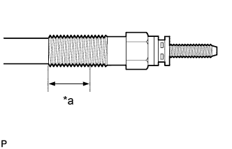
Apply adhesive to 3 or more thread roots in the area shown in the illustration.
Adhesive Toyota Genuine Adhesive 1324, Three Bond 1324 or equivalent Table 17. Text in Illustration *a 12 Thread Roots -
Using a 10 mm deep socket wrench, install the 8 glow plugs.
12 N*m 125 kgf*cm 9 ft.*lbf
-
- Click here
INSTALL NO. 1 GLOW PLUG CONNECTOR
-
Install the 2 glow plug connectors by uniformly tightening the 8 nuts.
2.2 N*m 22 kgf*cm 19 in.*lbf -
Install the 8 screw grommets.
-
Connect the 2 wire harnesses with the 2 nuts and 2 screw grommets.
4.0 N*m 41 kgf*cm 35 in.*lbf
-
- Click here
INSTALL WATER OUTLET PIPE
-
Install 2 new gaskets and the water outlet pipe with the 4 bolts.
21 N*m 214 kgf*cm 15 ft.*lbf Tip:The gasket claw should face toward the water outlet pipe.
-
- Click here
INSTALL WATER OUTLET
-
Install a new gasket and the water outlet with the 2 bolts, and then connect the water outlet to the No. 2 water hose joint.
21 N*m 214 kgf*cm 15 ft.*lbf
-
- Click here
INSTALL NO. 2 INTERCOOLER SUPPORT BRACKET
-
Install the No. 2 intercooler support bracket with the 2 bolts.
43 N*m 438 kgf*cm 32 ft.*lbf
-
- Click here
INSTALL CLUTCH FLEXIBLE HOSE BRACKET (for Manual Transmission)
-
Install the clutch flexible hose bracket with the 2 bolts.
20 N*m 204 kgf*cm 15 ft.*lbf
-
- Click here
INSTALL STARTER HOSE BRACKET
-
Install the starter hose bracket with the 2 bolts.
10 N*m 102 kgf*cm 7 ft.*lbf
-
- Click here
INSTALL STARTER ASSEMBLY
-
Install the starter with the 2 bolts.
80 N*m 816 kgf*cm 59 ft.*lbf -

Connect the 2 starter hoses.
Table 18. Text in Illustration *1 Yellow Mark -
Attach the harness clamp and connect the wire harness.
-
Connect the starter wire with the nut.
20 N*m 200 kgf*cm 14 ft.*lbf -
Connect the starter connector.
-
- Click here
INSTALL WATER PUMP ASSEMBLY
-
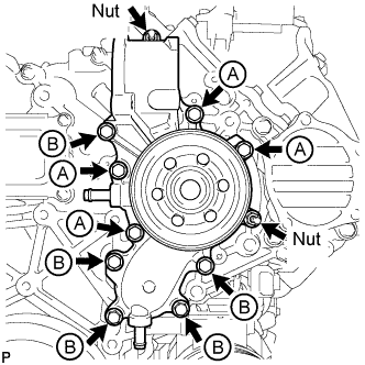
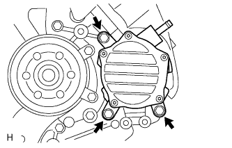
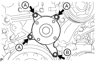
Temporarily install a new gasket and the water pump with the 9 bolts and 2 nuts.
Table 19. Bolt Length Item Length Bolt A 30 mm (1.18 in.) Bolt B 80 mm (3.15 in.) -
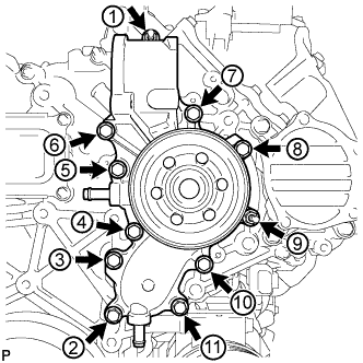
Uniformly tighten the 9 bolts and 2 nuts of the water pump in the order shown in the illustration.
25 N*m 250 kgf*cm 18 ft.*lbf Note:After installing all of the bolts and nuts, check that all of the bolts and nuts are tightened to the torque specification.
-
- Click here
CONNECT INLET WATER HOSE
- Click here
INSTALL NO. 2 IDLER PULLEY BRACKET (w/ Viscous Heater)
-
Temporarily install the No. 2 idler pulley bracket with the bolt.
-
Temporarily install the 2 bolts to the No. 2 idler pulley bracket bolt hole.
-
Uniformly tighten the 3 bolts of the No. 2 idler pulley bracket in the order shown in the illustration.
49 N*m 495 kgf*cm 36 ft.*lbf
-
- Click here
INSTALL NO. 2 IDLER PULLEY (w/ Viscous Heater)
-
Install the collar, No. 2 idler pulley and cover with the bolt.
49 N*m 495 kgf*cm 36 ft.*lbf
-
- Click here
INSTALL FAN BRACKET SUB-ASSEMBLY
-
Install the fan bracket with the 4 bolts.
21 N*m 214 kgf*cm 15 ft.*lbf Table 20. Bolt Length Item Length Bolt A 30 mm (1.18 in.) Bolt B 80 mm (3.15 in.)
-
- Click here
INSTALL TIMING GEAR COVER INSULATOR (w/ Intercooler)
-
w/o Viscous Heater:
Install the timing gear cover insulator with the 2 bolts.
21 N*m 214 kgf*cm 15 ft.*lbf -
w/ Viscous Heater:
Install the timing gear cover insulator.
-
- Click here
INSTALL THERMOSTAT
-
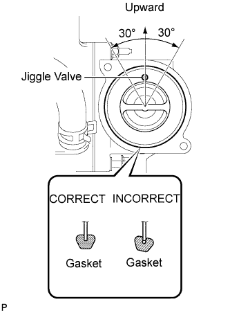
Install a new gasket to the thermostat.
Note:When installing the gasket to the thermostat, be careful not to deform the gasket. Make sure that the groove of the gasket is properly installed onto the thermostat, as shown in the illustration.
-
Insert the thermostat into the water pump with the jiggle valve facing straight upward.
Tip:The jiggle valve may be set within 30° of either side of the prescribed position.
-
- Click here
INSTALL WATER INLET
-
Install the water inlet with the 4 bolts.
for bolt A 21 N*m 214 kgf*cm 15 ft.*lbf for bolt B 25 N*m 250 kgf*cm 18 ft.*lbf -
Connect the No. 2 oil cooler hose to the clamp and water pump.
-
- Click here
INSTALL NO. 1 IDLER PULLEY BRACKET (w/ Viscous Heater)
-
Install the No. 1 idler pulley bracket with the bolt.
49 N*m 495 kgf*cm 36 ft.*lbf
-
-
Click here
INSTALL VISCOUS HEATER ASSEMBLY WITH MAGNET CLUTCH (w/ Viscous Heater)
-
Install the heater assembly with the 2 bolts.
48.5 N*m 495 kgf*cm 36 ft.*lbf -
Connect the 2 heater hoses.
-
Using pliers, grip the claws of the clips and slide the 2 clips.
-
Connect the connector and attach the clamp.
-
-
Click here
INSTALL CRANKSHAFT POSITION SENSOR
-
Apply a light coat of engine oil to the O-ring.
Note:When reusing the sensor, inspect the O-ring.
If the O-ring has scratches or cuts, replace the sensor.
-
Install the sensor with the bolt.
5.0 N*m 51 kgf*cm 44 in.*lbf -
Connect the sensor wire harness clamp.
-
-
Click here
INSTALL CAMSHAFT POSITION SENSOR
-
Apply a light coat of engine oil to the O-ring.
Note:When reusing the sensor, inspect the O-ring.
If the O-ring has scratches or cuts, replace the sensor.
-

Install the sensor with the bolt.
5.0 N*m 51 kgf*cm 44 in.*lbf -
Connect the sensor connector.
-
-
Click here
INSTALL NO. 1 OIL PAN SUB-ASSEMBLY
Note:When the contact surfaces shown below are wet, wipe them with an oil-free cloth before applying seal packing.
-
Install the cylinder block oil hole gasket.
-
Apply a light coat of engine oil to 3 new O-rings and set the 3 O-rings to the oil regulator and scavenging pump.
-
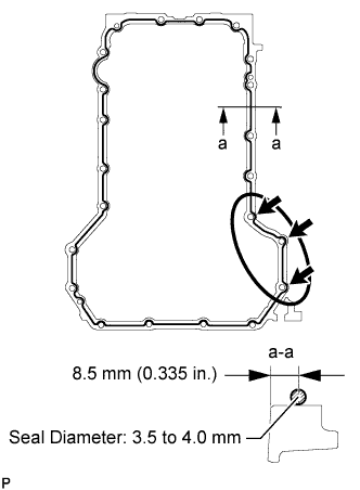
Apply seal packing to the No. 1 oil pan as shown in the illustration.
Standard seal diameter 3.5 to 4.0 mm (0.134 to 0.157 in.) Seal packing Toyota Genuine Seal Packing Black, Three Bond 1207B or equivalent Note:
-
For the 3 bolt holes labeled with arrows, apply the seal packing on the outer edges. For the other bolt holes, apply the seal packing on the inner edges.
-
Make sure to apply a continuous bead of seal packing as shown in the illustration. If the bead breaks, overlap 3 mm (0.118 in.) of seal packing and continue the bead.
-
Remove any oil and old seal packing from the contact surface.
-
Install the No. 1 oil pan within 3 minutes and tighten the bolts and nuts within 15 minutes after applying seal packing.
-
Do not start the engine for at least 2 hours after installing.
-
-
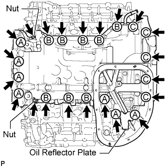
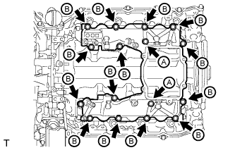
Install the No. 1 oil pan and oil reflector plate with the 20 bolts and 2 nuts.
25 N*m 250 kgf*cm 18 ft.*lbf Table 21. Bolt Length Item Quantity Length Bolt A 7 70 mm (2.76 in.) Bolt B 8 20 mm (0.787 in.) Bolt C 5 30 mm (1.18 in.)
-
- Click here
INSTALL OIL STRAINER SUB-ASSEMBLY
-
Apply a light coat of engine oil to a new O-ring, and install it to the oil strainer.
-
Install the oil strainer with the 2 bolts.
10 N*m 102 kgf*cm 7 ft.*lbf
-
-
Click here
INSTALL NO. 2 OIL PAN SUB-ASSEMBLY
Note:When the contact surfaces shown below are wet, wipe them with an oil-free cloth before applying seal packing.
-
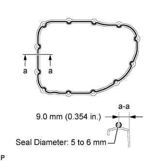
Apply seal packing to the No. 2 oil pan as shown in the illustration.
Standard seal diameter 5.0 to 6.0 mm (0.197 to 0.236 in.) Seal packing Toyota Genuine Seal Packing Black, Three Bond 1207B or equivalent Note:
-
For the bolt and pin holes, make sure to apply seal packing to the inner sides.
-
Make sure to apply a continuous bead of seal packing as shown in the illustration. If the bead breaks, overlap 3.0 mm (0.118 in.) of seal packing and continue the bead.
-
Remove any oil from the contact surface.
-
Install the No. 2 oil pan within 3 minutes and tighten the bolts and nuts within 10 minutes after applying seal packing.
-
Do not start the engine for at least 2 hours after installing.
-
-
Install the No. 2 oil pan with the 10 bolts and 2 nuts.
10 N*m 102 kgf*cm 7 ft.*lbf
-
- Click here
INSTALL ENGINE OIL LEVEL SENSOR
-
Install a new gasket and the sensor with the 4 bolts.
10 N*m 102 kgf*cm 7 ft.*lbf
-
- Click here
INSTALL OIL FILTER BRACKET SUB-ASSEMBLY
-
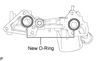
Apply a light coat of engine oil to 2 new O-rings, and set them to the oil filter bracket.
-
Install the oil filter bracket with the 3 bolts and 2 nuts.
21 N*m 214 kgf*cm 15 ft.*lbf -
Connect the 2 wire harness clamps.
-
- Click here
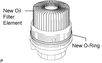
INSTALL OIL FILTER ELEMENT
-
Clean the inside of the oil filter cap, its threads and its O-ring groove.
-
Apply a small amount of engine oil to a new O-ring and install it to the oil filter cap.
-
Set a new oil filter element in the oil filter cap.
-
Remove any dirt or foreign matter from the installation surface of the engine.
-
Apply a small amount of engine oil to the O-ring again and temporarily install the oil filter cap by hand.
-
Using SST, tighten the oil filter cap.
09228-06501 25 N*m 255 kgf*cm 18 ft.*lbf Note:
-
Make sure that the oil filter is installed securely as shown in the illustration.
-
Be careful that the O-ring does not get caught between any surrounding parts.
-
-
Install the No. 2 engine under cover seal to the No. 2 engine under cover with the 2 bolts.
10 N*m 102 kgf*cm 7 ft.*lbf
-
- Click here
INSTALL TIMING GEAR COVER SPACER (w/ Intercooler)
-
Install the timing gear cover spacer with the 2 bolts.
21 N*m 214 kgf*cm 15 ft.*lbf
-
- Click here
INSTALL CRANKSHAFT PULLEY
Note:This procedure is intended for removal/installation of the crankshaft pulley only. Do not use this procedure for removal/installation of the flywheel or the drive plate and ring gear.
-
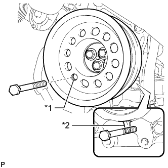
Align the crankshaft pulley and the crankshaft knock pin, and temporarily install the crankshaft pulley with the 3 bolts.
Table 22. Text in Illustration *1 Service Hole *2 Protrusion -
Install the 2 bolts to the bolt holes of the crankshaft rear side.
-
Using a bar, turn the crankshaft until the crankshaft pulley service hole is a little to the right of bottom dead center.
-
Install a 14 mm x 1.5 pitch service bolt with a length of 70 mm or more to the crankshaft pulley service hole, and hold the crankshaft using the timing chain cover protrusion.
-
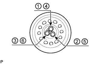
Uniformly tighten the 3 bolts in 2 passes in the order shown in the illustration.
115 N*m 1168 kgf*cm 84 ft.*lbf -
Remove the service bolt.
-
- Click here
CONNECT NO. 2 OIL COOLER HOSE
-
Align the white paint marks on the oil cooler hose and oil filter bracket and connect the hose. Then connect the other side to the water pump and attach the oil cooler hose to the clamp.
Note:Make sure to maintain a space between the oil cooler hose and crankshaft pulley, and the oil cooler hose and V-ribbed belt idler pulley.
-
- Click here
CONNECT NO. 1 OIL COOLER HOSE
- Click here
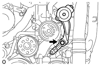
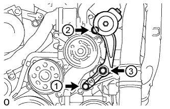
INSTALL V-RIBBED BELT TENSIONER ASSEMBLY
-
Install the V-ribbed belt tensioner with the 5 bolts.
for bolt A and C 43 N*m 438 kgf*cm 32 ft.*lbf for bolt B 21 N*m 214 kgf*cm 15 ft.*lbf Table 23. Bolt Length Item Quantity Length Bolt A 1 116 mm (4.57 in.) Bolt B 2 40 mm (1.58 in.) Bolt C 2 95 mm (3.74 in.) -
Install the No. 1 idler pulley with the bolt.
43 N*m 438 kgf*cm 32 ft.*lbf -
Install the V-ribbed belt tensioner bracket with the 3 bolts.
10 N*m 102 kgf*cm 7 ft.*lbf
-
- Click here
INSTALL STIFFENER INSULATOR RH (w/ Intercooler)
-
Install the stiffener insulator RH with the 2 bolts.
10 N*m 102 kgf*cm 7 ft.*lbf
-
- Click here
INSTALL COMPRESSOR BRACKET
-
Install the compressor bracket with the bolt.
21 N*m 214 kgf*cm 15 ft.*lbf
-
- Click here
INSTALL NO. 2 CYLINDER BLOCK INSULATOR
- Click here
INSTALL ENGINE MOUNTING BRACKET LH
-
Install the engine mounting bracket LH with the 4 bolts.
80 N*m 816 kgf*cm 59 ft.*lbf
-
- Click here
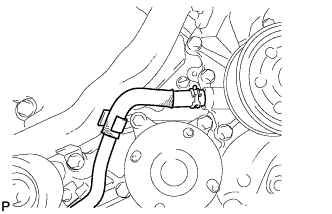
INSTALL NO. 2 WATER BY-PASS PIPE SUB-ASSEMBLY
-
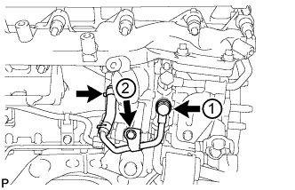
Temporarily install a new gasket and No. 2 water by-pass pipe with the union bolt and 2 bolts.
-
Tighten the union bolt and 2 bolts of the No. 2 water by-pass pipe in the order shown in the illustration.
for union bolt 35 N*m 357 kgf*cm 26 ft.*lbf for bolt 10 N*m 102 kgf*cm 7 ft.*lbf
-
- Click here
INSTALL NO. 3 VACUUM TRANSMITTING PIPE SUB-ASSEMBLY
-
Install the No. 3 vacuum transmitting pipe with the 2 bolts.
6.0 N*m 61 kgf*cm 53 in.*lbf -
w/ Intercooler:
Connect the vacuum hose.
-
- Click here
INSTALL TURBOCHARGER WIRE
-
Install the turbocharger wire with the 2 bolts.
21 N*m 214 kgf*cm 15 ft.*lbf -
Attach the 3 wire harness clamps.
-
- Click here
INSTALL NO. 2 INTAKE AIR CONNECTOR BRACKET
-
Install the No. 2 intake air connector bracket with the bolt.
21 N*m 214 kgf*cm 15 ft.*lbf -
Attach the 2 wire clamps.
-
- Click here
INSTALL NO. 1 CYLINDER BLOCK INSULATOR
- Click here
INSTALL ENGINE MOUNTING BRACKET RH
-
Install the engine mounting bracket RH with the 4 bolts.
80 N*m 816 kgf*cm 59 ft.*lbf
-
- Click here
INSTALL NO. 4 VACUUM TRANSMITTING PIPE SUB-ASSEMBLY (w/ Intercooler)
-
Install the No. 4 vacuum transmitting pipe with the 2 bolts.
6.0 N*m 61 kgf*cm 53 in.*lbf -
Connect the vacuum hose.
-
- Click here
INSTALL NO. 1 WATER BY-PASS PIPE SUB-ASSEMBLY
-
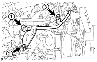
Temporarily install a new gasket and the No. 1 water by-pass pipe with the union bolt and bolt.
-
Tighten the union bolt and bolt of the No. 1 water by-pass pipe in the order shown in the illustration.
for union bolt 35 N*m 357 kgf*cm 26 ft.*lbf for bolt 10 N*m 102 kgf*cm 7 ft.*lbf
-
- Click here
INSTALL AIR TUBE SUPPORT
-
Install the air tube support with the 2 bolts.
21 N*m 214 kgf*cm 15 ft.*lbf
-
- Click here
INSTALL NO. 1 INTAKE AIR CONNECTOR BRACKET
-
Install the No. 1 intake air connector bracket with the 2 bolts.
21 N*m 214 kgf*cm 15 ft.*lbf
-
- Click here
INSTALL NO. 2 TURBOCHARGER SUB-ASSEMBLY WITH EXHAUST MANIFOLD LH
-
Install a new gasket to the No. 2 turbocharger.
-
Install the exhaust manifold LH to the No. 2 turbocharger with 3 new nuts.
69 N*m 704 kgf*cm 51 ft.*lbf Tip:The gasket claw should face toward the outside of the vehicle.
-
w/ DPF:
-
Install 2 new gaskets to the No. 2 exhaust manifold pipe.
Tip:The gasket claws should face the No. 2 exhaust manifold pipe.
-
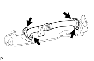
Temporarily install the No. 2 exhaust manifold pipe with the 4 bolts.
Tip:Install the No. 2 exhaust manifold pipe so that it is oriented as shown in the illustration.
-
Tighten the 4 bolts.
21 N*m 214 kgf*cm 15 ft.*lbf
-
-
Install a new gasket to the cylinder head LH.
-
Install the No. 2 turbocharger with exhaust manifold LH and 10 collars to the cylinder head LH with 10 new nuts.
36 N*m 367 kgf*cm 27 ft.*lbf Table 24. Text in Illustration *A w/ DPF *B w/o DPF Tip:Install the collars with the colored side facing the nuts.
-
Install a new gasket and the No. 2 inlet turbo oil pipe to the No. 1 oil pan with the union bolt.
29 N*m 296 kgf*cm 21 ft.*lbf -
Connect the 2 connectors to the turbocharger.
-
- Click here
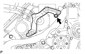
INSTALL NO. 2 VENTILATION TUBE SUB-ASSEMBLY
-
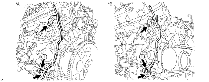
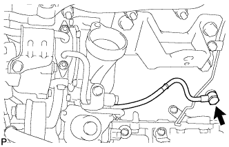
Temporarily install a new gasket and the No. 2 ventilation tube with the union bolt and bolt.
Table 25. Text in Illustration *A w/ DPF *B w/o DPF -
Tighten the union bolt and bolt in the order shown in the illustration.
for union bolt 29 N*m 296 kgf*cm 21 ft.*lbf for bolt 10 N*m 102 kgf*cm 7 ft.*lbf Note:Clean and remove any oil in the area labeled 1 in the illustration.
-
Connect the hose.
-
- Click here
INSTALL NO. 2 TURBOCHARGER STAY
-
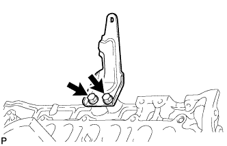
Install the No. 2 turbocharger stay with the 2 bolts.
49 N*m 495 kgf*cm 36 ft.*lbf
-
- Click here
CONNECT NO. 2 OUTLET TURBO OIL HOSE
Tip: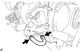
Align the white paint marks on the oil hose and pipe, and connect the hose.
Table 26. Text in Illustration *1 Painted Mark - Click here
INSTALL NO. 2 TURBO WATER PIPE SUB-ASSEMBLY
-
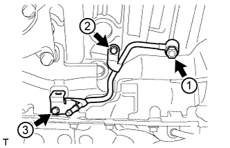
Temporarily install a new gasket and the No. 2 turbo water pipe with the union bolt and bolt.
-
Tighten the union bolt and bolt in the order shown in the illustration.
for union bolt 35 N*m 357 kgf*cm 26 ft.*lbf for bolt 10 N*m 102 kgf*cm 7 ft.*lbf -
Connect the water hose to the pipe.
-
- Click here
INSTALL FRONT WATER BY-PASS JOINT
-
Install a new gasket and the front water by-pass joint.
50 N*m 510 kgf*cm 37 ft.*lbf
-
- Click here
INSTALL NO. 3 TURBO WATER PIPE SUB-ASSEMBLY
-
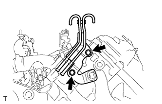
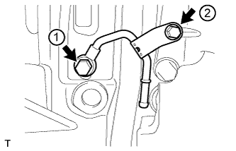
Temporarily install a new gasket and the No. 3 turbo water pipe with the union bolt and 2 bolts.
-
Tighten the union bolt and 2 bolts in the order shown in the illustration.
for union bolt 35 N*m 357 kgf*cm 26 ft.*lbf for bolt 10 N*m 102 kgf*cm 7 ft.*lbf
-
- Click here
INSTALL NO. 2 EXHAUST MANIFOLD HEAT INSULATOR
-
Install the No. 2 exhaust manifold heat insulator with the 3 bolts.
25 N*m 255 kgf*cm 18 ft.*lbf
-
- Click here
CONNECT NO. 2 TURBO WATER HOSE
- Click here
CONNECT BREATHER PLUG LH
-
Install the breather plug LH.
-
w/o DPF:
Attach the clamp.
-
Connect the hose.
-
- Click here
CONNECT NO. 3 VENTILATION HOSE
- Click here
INSTALL NO. 1 TURBOCHARGER SUB-ASSEMBLY WITH EXHAUST MANIFOLD RH
-
Install a new gasket to the No. 1 turbocharger.
-
Install the exhaust manifold RH to the No. 1 turbocharger with 2 new nuts and the bolt.
69 N*m 704 kgf*cm 51 ft.*lbf -
w/ DPF:
-
Install 2 new gaskets to the No. 1 exhaust manifold pipe.
Tip:The gasket claws should face the No. 1 exhaust manifold pipe.
-
Temporarily install the No. 1 exhaust manifold pipe with the 4 bolts.
Tip:Install the No. 1 exhaust manifold pipe so that it is oriented as shown in the illustration.
-
Tighten the 4 bolts.
21 N*m 214 kgf*cm 15 ft.*lbf
-
-
Install a new gasket to the cylinder head RH.
-
Install the No. 1 turbocharger with exhaust manifold RH to the cylinder head RH with the 10 collars and 10 new nuts.
36 N*m 367 kgf*cm 27 ft.*lbf Table 27. Text in Illustration *A w/ DPF *B w/o DPF Tip:Install the collars with the colored side facing the nuts.
-
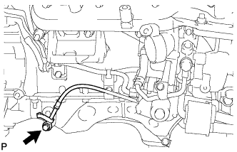
Install a new gasket and the No. 1 inlet turbo oil pipe to the cylinder block with the union bolt.
When "dry" 29 N*m 296 kgf*cm 21 ft.*lbf When "wet" 23 N*m 235 kgf*cm 17 ft.*lbf Note:
-
The parts are "dry" when there is absolutely no engine oil on the union bolt and cylinder block bolt hole.
-
The parts are "wet" when there is engine oil on the union bolt and cylinder block bolt hole.
-
-
- Click here
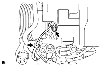
INSTALL NO. 1 VENTILATION TUBE SUB-ASSEMBLY
-
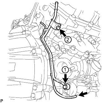
Temporarily install a new gasket and the No. 1 ventilation tube with the union bolt and bolt.
-
Tighten the union bolt and bolt in the order shown in the illustration.
for union bolt 29 N*m 296 kgf*cm 21 ft.*lbf for bolt 10 N*m 102 kgf*cm 7 in.*lbf Note:Clean and remove any oil in the area labeled 1 in the illustration.
-
Connect the hose.
-
- Click here
INSTALL NO. 1 TURBOCHARGER STAY
-
Temporarily install the No. 1 turbocharger stay with the 2 bolts.
-
Tighten the 2 bolts.
49 N*m 495 kgf*cm 36 ft.*lbf
-
- Click here
INSTALL NO. 1 TURBO WATER PIPE SUB-ASSEMBLY
-
Install a new gasket and the No. 1 turbo water pipe with 2 new nuts and the 3 bolts.
10 N*m 102 kgf*cm 7 ft.*lbf Table 28. Text in Illustration *1 New Nut -
Connect the water hose.
-
- Click here
CONNECT NO. 1 OUTLET TURBO OIL HOSE
- Click here
INSTALL NO. 1 EXHAUST MANIFOLD HEAT INSULATOR
-
Install the No. 1 exhaust manifold heat insulator with the 3 bolts.
25 N*m 255 kgf*cm 18 ft.*lbf
-
- Click here
CONNECT NO. 2 TURBO WATER HOSE
- Click here
CONNECT BREATHER PLUG RH
-
Install the breather plug RH and attach the clamp.
-
Connect the hose.
-
- Click here
CONNECT NO. 2 VENTILATION HOSE
- Click here
INSTALL GENERATOR ASSEMBLY
-
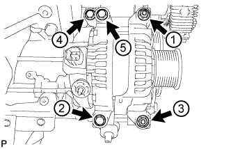
Temporarily install the generator with the 3 bolts and 2 nuts.
-
Uniformly tighten the 3 bolts and 2 nuts in the order shown in the illustration.
21 N*m 214 kgf*cm 15 ft.*lbf -
Connect the generator cable and install the nut and bolt.
for bolt 13 N*m 133 kgf*cm 10 ft.*lbf for nut (130A Type and 150A Type:) 9.8 N*m 100 kgf*cm 87 in.*lbf for nut (180A Type:) 12 N*m 122 kgf*cm 9 ft.*lbf
-
- Click here
INSTALL NO. 1 INTAKE AIR CONNECTOR PIPE
-
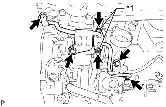
Install the No. 1 intake air connector pipe with the bolt. Then tighten the hose clamp.
for bolt 21 N*m 214 kgf*cm 15 ft.*lbf for hose clamp 6.0 N*m 61 kgf*cm 53 in.*lbf -
Connect the 4 connectors and attach the 5 wire harness clamps.
-
- Click here
INSTALL NO. 1 ENGINE OIL LEVEL DIPSTICK GUIDE
-
Apply a light coat of engine oil to a new O-ring, and install it to the No. 1 engine oil level dipstick guide.
-
Install the No. 1 engine oil level dipstick guide with the 2 bolts.
10 N*m 102 kgf*cm 7 ft.*lbf
-
- Click here
INSTALL ENGINE ASSEMBLY
-
Install the engine assembly to the vehicle (Click here).
-
- Click here
CONNECT CABLE TO NEGATIVE BATTERY TERMINAL
Note:When disconnecting the cable, some systems need to be initialized after the cable is reconnected (Click here).
-
Connect the cables to the negative (-) main battery and sub-battery terminals.
-