CAMSHAFT (w/ DPF) REMOVAL

CAUTION:
When replacing an injector (including interchanging injectors between cylinders), common rail, cylinder head, or intake manifold, replace the corresponding injection pipes with a new one.
Note
When fuel lines are disconnected, air may enter the fuel lines, leading to engine starting trouble. Therefore, perform forced regeneration and bleed the air from the fuel lines.
-
CHECK INJECTOR COMPENSATION CODE
Note
-
When an injector assembly is replaced, the new injector compensation code must be input into the ECM. When the ECM is replaced, all of the existing injector compensation codes must be input into the new ECM.
-
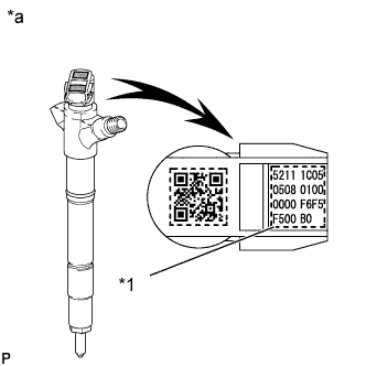
Injector compensation codes are unique, 30-digit, alphanumeric values printed on the head portion of each injector assembly. If an incorrect injector compensation code is input into the ECM, the engine assembly may rattle or engine idling may become rough. In addition, engine failure may occur and the life of the engine may be shortened.
-
When an injector compensation code is input into the ECM, the pilot quantity learning values stored in the ECM are initialized. Also, DTC P062F is stored when the pilot quantity learning values are initialized.
Text in Illustration *1 Injector Compensation Code *a Example
-
After replacing injector assemblies with new one(s), input injector compensation code(s) of the injector assemblies into the ECM as follows:
Tech Tips
-
Each injector assembly has different fuel injection characteristics. In order to optimize the fuel injections, the ECM uses the compensation codes to balance the different fuel injections between each injector assembly.
-
When only one or more injector assemblies are replaced, input the injector compensation code(s), perform pilot quantity learning, and then clear the DTCs.
-
When the engine switch is turned on (IG) after replacing the ECM, DTC P062F is stored. This indicates that the injector compensation code(s) need to be registered. Manually clear the DTC upon completion of pilot quantity learning.
-
Input the compensation code(s), which is/are imprinted on the head portion(s) of the new injector assemblies, into the GTS.
-
Input the new injector compensation code(s) into the ECM using the GTS.
-
Turn the GTS off and turn the engine switch off.
-
Wait for at least 30 seconds.
-
Turn the engine switch on (IG) and turn the GTS on.
-
Perform pilot quantity learning.
-
Clear DTC P062F stored in the ECM using the GTS Click here.
Note
If the DTCs are cleared without performing pilot quantity learning, DTC P062F is stored immediately after clearing DTCs.
-
-
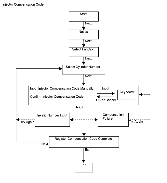
Register compensation codes.
-
Connect the GTS to the DLC3.
-
Turn the engine switch on (IG).
Note
Do not start the engine.
-
Turn the GTS on.
-
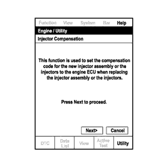
Enter the following menus: Engine and ECT / Utility / Injector Compensation.
-
Press Next.
-
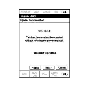
Press Next again to proceed.
-
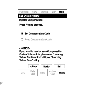
Select "Set Compensation Code".
-
Press Next.
-
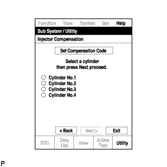
Select the number of the cylinder corresponding to the injector compensation code that you want to register.
-
Press Next.
-
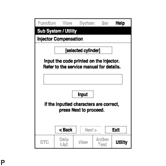
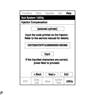
Register compensation code.
-
Press Input.
-
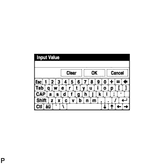
Manually input the cylinder compensation code using the keyboard on the GTS screen. The code is a 30-digit, alphanumeric value printed on the injector head portion.
Tech Tips
Each injector compensation code is unique. The compensation code for each selected cylinder must be input into the GTS correctly.
-
Confirm that the compensation code for the selected cylinder is correct, and then press OK.
-
-
Check that the compensation code displayed on the screen is correct by comparing it with the 30-digit alphanumeric value on the head portion of the injector assembly.
Note
If an incorrect injector compensation code is input into the ECM, the engine may rattle or engine idling may become rough. In addition, engine failure may occur and the life of the engine may be shortened.
Tech Tips
-
If a wrong compensation code is input or read, return to the Input Value screen by pressing Input.
-
The saving process may fail due to a problem with the wire harness or a bad connection with the DLC3. Check the wire harness and DLC3 connection. If no problem is found with either, the ECM may be malfunctioning. Check the ECM and repeat this operation.
-
-
Press Next to register the injector compensation code in the ECM.
Tech Tips
-
If the registration process fails, the injector compensation code may be incorrect. Check the injector compensation code again.
-
If the input injector compensation code fails to register even though it is input correctly, there may be a problem with the wire harness or a bad connection with the DLC3. Check the wire harness and DLC3 connection. If no problem is found with either, the ECM may be malfunctioning. Check the ECM and restart this operation.
-
-
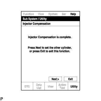
If you want to continue with other compensation code registrations, press Next. To finish the registration, press Exit.
-
Turn the GTS off and turn the engine switch off.
-
Wait for at least 30 seconds.
-
Turn the engine switch on (IG), and then turn the GTS on.
-
Perform pilot quantity learning.
-
Clear DTC P062F stored in the ECM using the GTS Click here.
Note
If the DTCs are cleared without performing pilot quantity learning, DTC P062F is stored immediately after clearing DTCs.
-
-
-
PRECAUTION
Note
After turning the ignition switch off, waiting time may be required before disconnecting the cable from the battery terminal. Therefore, make sure to read the disconnecting the cable from the battery terminal notice before proceeding with work Click here.
-
DISCONNECT CABLE FROM NEGATIVE BATTERY TERMINAL
Note
When disconnecting the cable some systems need to be initialized after the cable is reconnected Click here.
-
REMOVE COWL TOP VENTILATOR LOUVER SUB-ASSEMBLY
-
DRAIN ENGINE OIL
-
Remove the 2 bolts and No. 2 engine under cover seal from the No. 2 engine under cover.
-
Remove the oil filler cap.
-
Remove the oil pan drain plug and gasket, and then drain the engine oil into a container.
-
Install a new gasket and the oil pan drain plug.
- Torque:
- 38 N*m { 387 kgf*cm, 28 ft.*lbf }
-
-
REMOVE FRONT WHEEL
-
REMOVE FRONT FENDER SPLASH SHIELD SUB-ASSEMBLY LH
-
Remove the 3 bolts and screw.
-
Loosen the clip and remove the front fender splash shield LH.
-
-
REMOVE FRONT FENDER SPLASH SHIELD SUB-ASSEMBLY RH
-
Remove the 3 bolts and 2 screws.
-
Loosen the clip and remove the front fender splash shield RH.
-
-
REMOVE NO. 1 ENGINE UNDER COVER SUB-ASSEMBLY
-
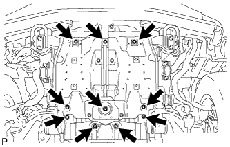
Remove the 10 bolts and No. 1 engine under cover.
-
-
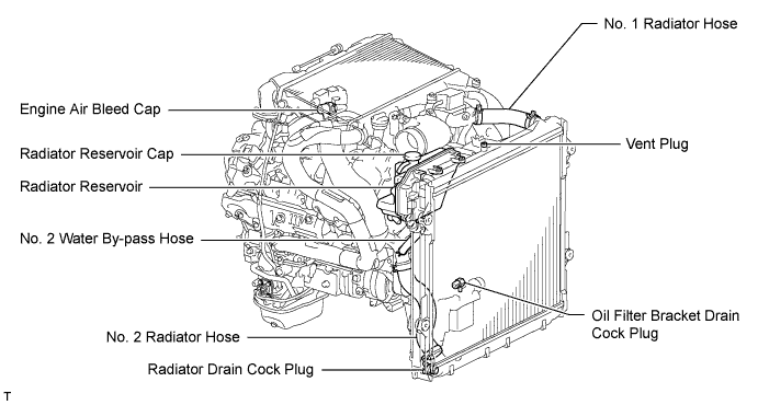
DRAIN ENGINE COOLANT
CAUTION:
Do not remove the radiator reservoir cap while the engine and radiator are still hot. Pressurized, hot engine coolant and steam may be released and cause serious burns.
Tech Tips
Collect the coolant in a container and dispose of it according to the regulations in your area.
-
Loosen the radiator drain cock plug.
-
Remove the radiator reservoir cap to drain the coolant in the radiator.
-
Loosen the oil filter bracket drain cock plug to drain the coolant in the engine.
-
Tighten the radiator drain cock plug by hand.
-
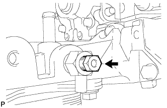
Tighten the oil filter bracket drain cock plug.
- Torque:
- 13 N*m { 133 kgf*cm, 10 ft.*lbf }
-
-
REMOVE UPPER RADIATOR SUPPORT SEAL
-
Remove the 7 clips and upper radiator support seal.
-
-
REMOVE NO. 3 ENGINE ROOM WIRE
-
Disconnect the 4 wire harness clamps.
-
Remove the 2 nuts and No. 3 engine room wire.
-
-
REMOVE NO. 1 ENGINE COVER SUB-ASSEMBLY
-
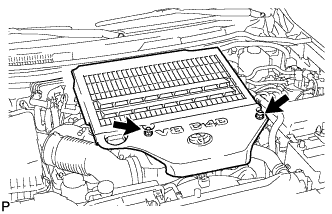
Remove the 2 nuts and No. 1 engine cover.
-
-
REMOVE AIR CLEANER CAP SUB-ASSEMBLY
-
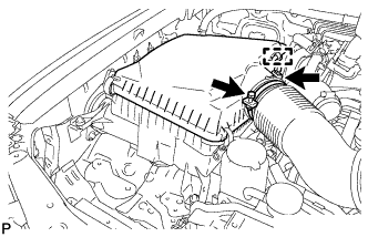
Loosen the hose clamp.
-
Disconnect the mass air flow meter connector and using a clip remover, detach the wire harness clamp from the air cleaner cap.
-
Detach the 4 clamps and remove the air cleaner cap.
-
-
REMOVE NO. 1 AIR CLEANER HOSE
-
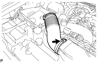
Loosen the hose clamp and remove the No. 1 air cleaner hose.
-
-
REMOVE INTAKE AIR CONNECTOR
-
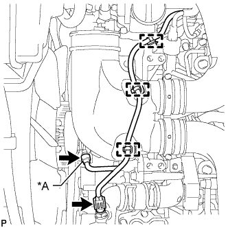
Text in Illustration *A w/ Viscous Heater w/ Viscous Heater:
Disconnect the 2 connectors from the viscous with magnet clutch heater and water temperature sensor.
-
w/o Viscous Heater:
Disconnect the connector from the water temperature sensor.
-
Using a clip remover, detach the 3 wire harness clamps.
-
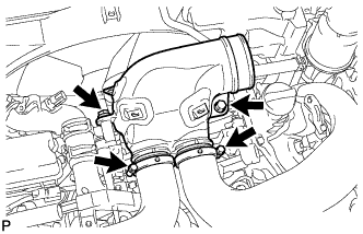
Loosen the 2 hose clamps and remove the 2 bolts and intake air connector.
-
-
REMOVE V-RIBBED BELT (w/ Viscous Heater)
-
Loosen the lock nut and turn the bolt counterclockwise.
-
Remove the V-ribbed belt.
-
-
REMOVE NO. 1 IDLER PULLEY (w/ Viscous Heater)
-
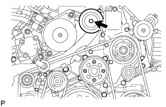
Remove the bolt, cover, No. 1 idler pulley and collar.
-
-
REMOVE NO. 3 IDLER PULLEY (w/ Viscous Heater)
-
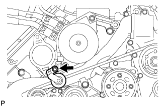
Remove the nut and No. 3 idler pulley.
-
-
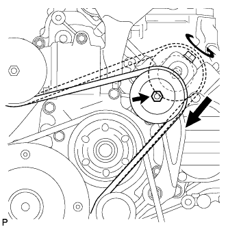
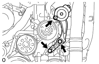
REMOVE V-RIBBED BELT
-
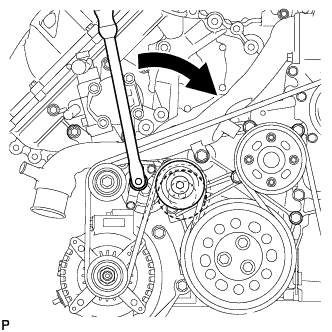
Using a wrench to the V-ribbed belt tensioner bracket, turn the wrench clockwise and remove the V-ribbed belt.
-
-
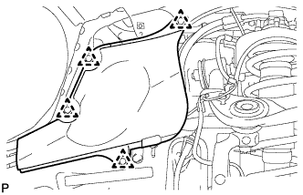
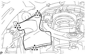
REMOVE FRONT FENDER APRON SEAL FRONT RH
-
Remove the 3 clips and front fender apron seal front RH.
-
-
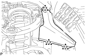
REMOVE FRONT FENDER APRON SEAL REAR RH
-
Remove the 4 clips and front fender apron seal rear RH.
-
-
REMOVE FRONT FENDER APRON SEAL FRONT LH
-
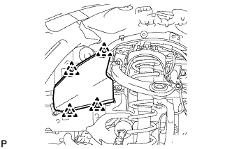
w/o KDSS:
Remove the 4 clips and front fender apron seal front LH.
-
w/ KDSS:
Remove the 3 clips and front fender apron seal front LH.
-
-
REMOVE FRONT FENDER APRON SEAL REAR LH
-
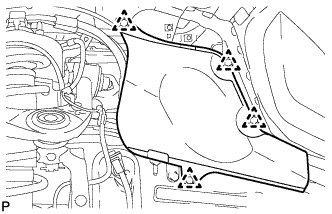
Remove the 4 clips and front fender apron seal rear LH.
-
-
REMOVE VANE PUMP OIL RESERVOIR ASSEMBLY
-
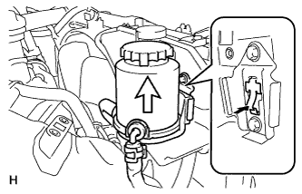
Insert a screwdriver between the reservoir and oil reservoir bracket, push the claw, and then disconnect the reservoir by pulling it upwards.
-
-
REMOVE NO. 1 OIL RESERVOIR BRACKET
-
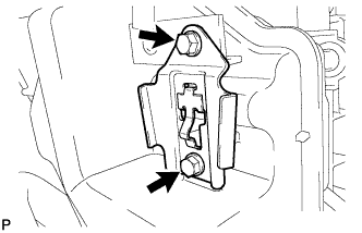
Remove the 2 bolts and bracket.
-
-
REMOVE RADIATOR RESERVOIR ASSEMBLY
-
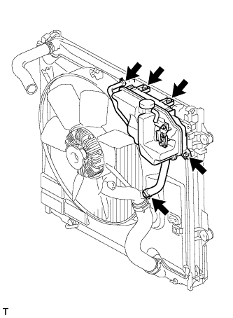
Disconnect the 2 hoses.
-
Remove the 3 bolts and radiator reservoir.
-
-
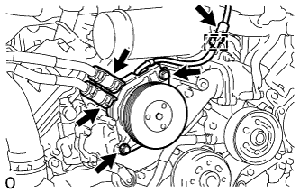
REMOVE VANE PUMP ASSEMBLY
-
Remove the 2 nuts and vane pump.
-
Remove the O-ring from the vane pump.
-
-
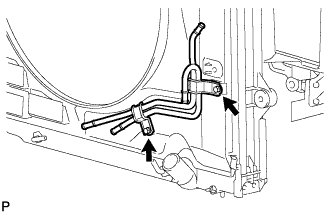
REMOVE OIL COOLER TUBE
-
Disconnect the inlet and outlet No. 1 oil cooler hose.
-
Disconnect the inlet No. 2 and No. 3 oil cooler hoses.
-
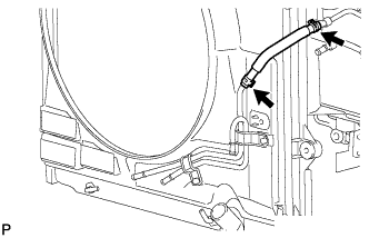
Disconnect the inlet No. 4 oil cooler hose.
-
Remove the 2 bolts and transmission oil cooler tube.
-
-
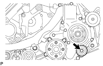
REMOVE FAN SHROUD WITH FAN
-
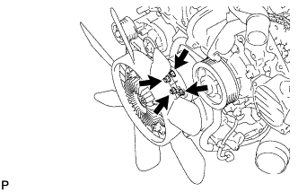
Loosen the 4 nuts holding the fluid coupling fan.
-
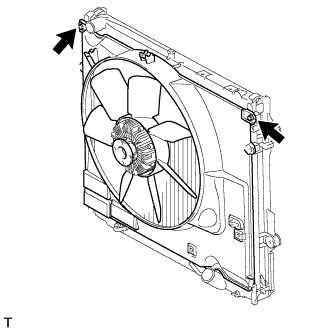
Remove the 2 bolts holding the fan shroud.
-
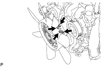
Remove the 4 nuts of the fluid coupling fan, and then remove the shroud together with the fluid coupling fan.
-
-
REMOVE INTERCOOLER ASSEMBLY
-
Loosen the No. 1 air hose clamp.
-
Loosen the No. 2 air hose clamp.
-
Disconnect the turbo pressure sensor connector, intake air temperature sensor connector and vacuum hose.
-
Remove the 6 nuts, 2 bolts and intercooler.
-
Remove the 2 gaskets from the air tube LH and RH.
-
-
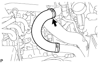
REMOVE NO. 1 AIR HOSE
-
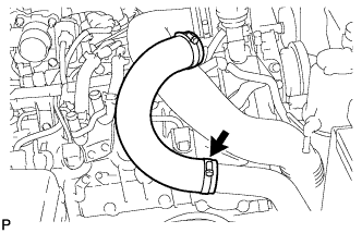
Loosen the hose clamp and remove the No. 1 air hose.
-
-
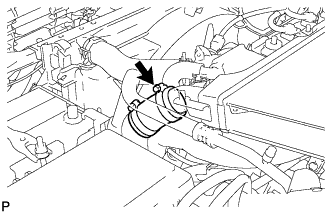
REMOVE NO. 2 AIR HOSE
-
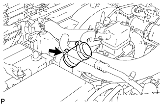
Loosen the hose clamp and remove the No. 2 air hose.
-
-
REMOVE NO. 2 ENGINE OIL LEVEL DIPSTICK GUIDE
-
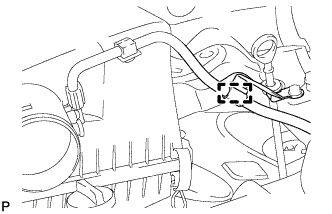
Disconnect the wire harness clamp from the No. 2 engine oil level dipstick guide.
-
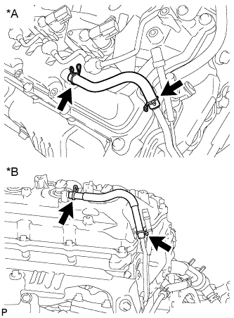
Text in Illustration *A w/ DPF *B w/o DPF Disconnect the ventilation hose from the cylinder head cover RH.
-
Remove the 2 bolts and No. 2 engine oil level dipstick guide.
-
Remove the O-ring from the No. 2 engine oil level dipstick guide.
-
-
REMOVE AIR TUBE SUB-ASSEMBLY RH
-
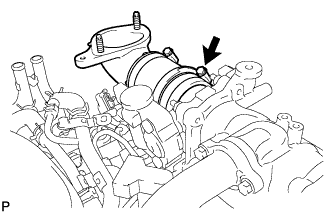
Loosen the hose clamp.
-
Remove the air tube from the throttle body.
-
-
REMOVE AIR TUBE SUB-ASSEMBLY LH
-
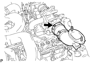
Loosen the hose clamp.
-
Remove the air tube from the throttle body.
-
-
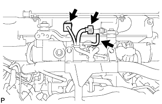
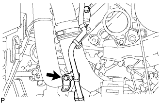
DISCONNECT WATER HOSE SUB-ASSEMBLY
Text in Illustration *A w/ Rear Heater *B w/o Rear Heater -
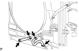
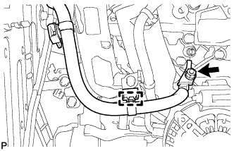
REMOVE NO. 3 WATER BY-PASS PIPE (w/o Viscous Heater)
-
Remove the 2 bolts and disconnect the 2 water hose ends, and then remove the No. 3 water by-pass pipe.
-
-
REMOVE HEATER WATER PIPE SUB-ASSEMBLY (w/ Viscous Heater)
-
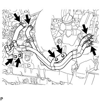
Remove the 4 bolts and disconnect the 4 water hose ends, and then remove the heater water pipe.
-
-
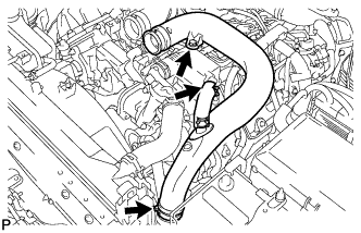
REMOVE NO. 3 AIR TUBE
-
Disconnect the wire harness from the clamp.
-
Remove the nut and ground wire.
-
Remove the bolt and disconnect the wire harness bracket.
-
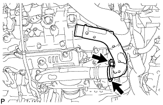
Loosen the hose clamp and remove the bolt and No. 3 air tube.
-
-
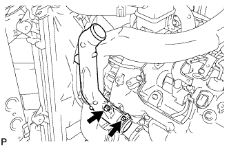
REMOVE NO. 1 AIR CLEANER PIPE SUB-ASSEMBLY
-
Loosen the hose clamp.
-
Remove the bolt and No. 1 air cleaner pipe.
-
-
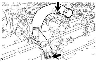
REMOVE NO. 4 AIR TUBE
-
Remove the bolt and disconnect the suction hose.
-
Loosen the hose clamp and remove the bolt and No. 4 air tube.
-
-
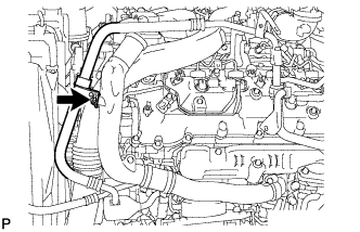
REMOVE NO. 2 AIR CLEANER PIPE SUB-ASSEMBLY
-
Disconnect the ventilation hose from the oil separator.
-
Loosen the hose clamp.
-
Remove the bolt and No. 2 air cleaner pipe.
-
-
REMOVE VISCOUS HEATER ASSEMBLY WITH MAGNET CLUTCH (w/ Viscous Heater)
-
Disconnect the connector and detach the clamp.
-
Using pliers, grip the claws of the clips and slide the 2 clips.
-
Disconnect the 2 heater hoses.
-
Remove the 2 bolts and heater assembly.
-
-
REMOVE NO. 1 IDLER PULLEY BRACKET (w/ Viscous Heater)
-
Remove the bolt and No. 1 idler pulley bracket.
-
-
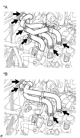
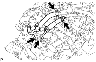
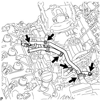
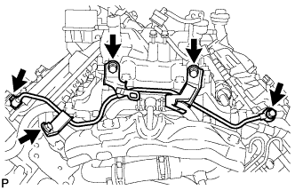
REMOVE NO. 4 WATER BY-PASS PIPE
-
w/ EGR System:
-
Remove the 2 bolts and nut.
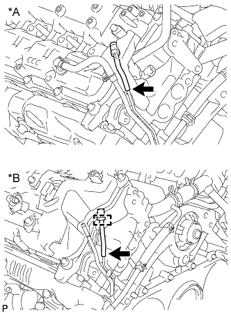
Text in Illustration *A w/ DPF *B w/o DPF -
w/ DPF:
Disconnect the 3 water hose ends, and then remove the No. 4 water by-pass pipe.
-
w/o DPF:
Disconnect the 4 water hose ends, and then remove the No. 4 water by-pass pipe.
-
-
w/o EGR System:
-
Remove the 2 bolts and nut.
-
Disconnect the 3 water hose ends, and then remove the No. 4 water by-pass pipe.
-
-
-
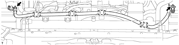
DISCONNECT FUEL HOSE
-
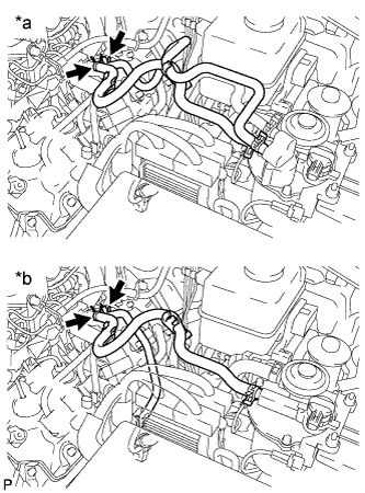
Text in Illustration *a for Fuel Filter with Heater *b for Fuel Filter without Heater w/ DPF:
-
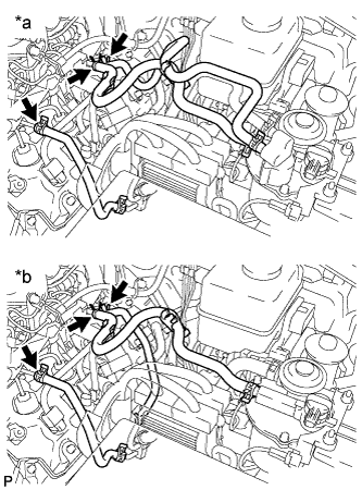
Text in Illustration *a for Fuel Filter with Heater *b for Fuel Filter without Heater w/o DPF:
-
-
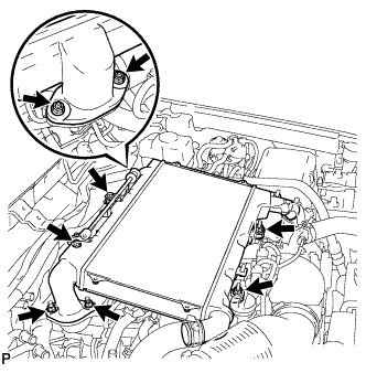
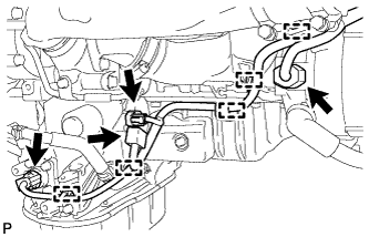
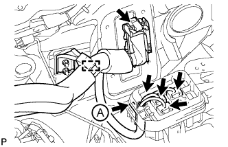
DISCONNECT ENGINE WIRE
-
LH Side:
-
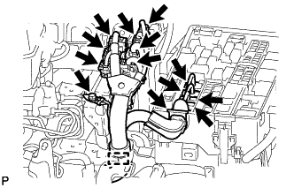
Disconnect the 7 connectors from the injector driver.
-
Remove the 4 connectors and detach the wire harness holder from the relay block.
-
Remove the bolt and disconnect the ground wire.
-
Disconnect the wire harness from the wire harness clamp holder.
-
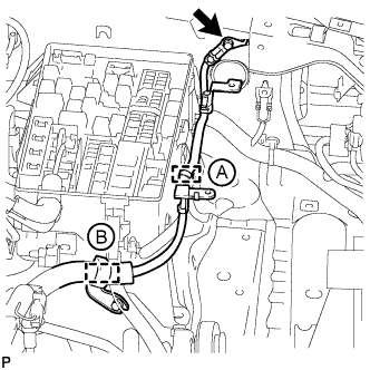
Remove the bolt and disconnect the ground wire from the body panel.
-
Using a clip remover, detach the ground wire clamp from the relay block side labeled A.
-
Disconnect the wire harness from the wire harness clamp holder labeled B.
-
Disconnect the 4 connectors.
-
Using a clip remover, detach the 3 wire harness clamps.
-
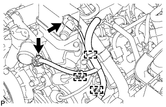
Disconnect the 2 connectors.
-
Using a clip remover, detach the 3 wire harness clamps.
-
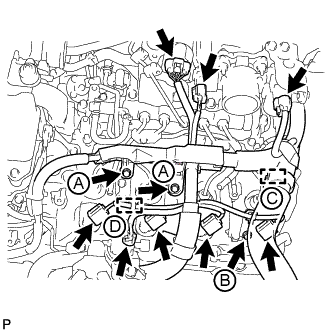
Disconnect the 8 connectors.
-
Remove the bolt and engine wire harness bracket labeled B.
-
Using a clip remover, detach the wire harness clamp labeled D.
-
Remove the 2 bolts and disconnect the engine wire protector labeled A.
-
for RHD:
Disconnect the wire harness from the wire harness clamp holder labeled C.
-
-
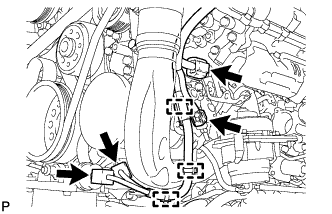
RH Side:
-
Disconnect the 4 connectors.
-
Using a clip remover, detach the 5 wire harness clamps.
-
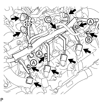
Disconnect the 7 connectors.
-
Using a clip remover, detach the wire harness clamp.
-
Remove the 3 bolts and disconnect the wire harness protector labeled A.
-
Remove the bolt and wire harness bracket labeled B.
-
Remove the nut and glow plug wire harness labeled C.
-
-
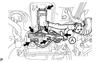
for LHD:
-
Disconnect the 4 connectors, and detach the wire harness tab from the relay block labeled A.
-
Disconnect the ECM connector.
-
Disconnect the wire harness from the wire harness clamp holder.
-
-
for RHD:
-
Disconnect the wire harness from the wire harness clamp holder.
-
Remove the bolt and wire harness clamp holder.
-
Disconnect the 4 connectors, and detach the wire harness tab from the relay block labeled A.
-
Disconnect the ECM connector.
-
Disconnect the wire harness from the wire harness clamp holder.
-
-
-
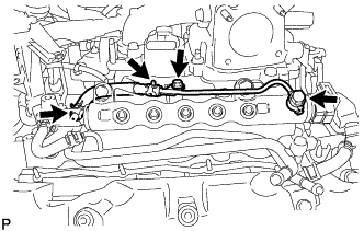
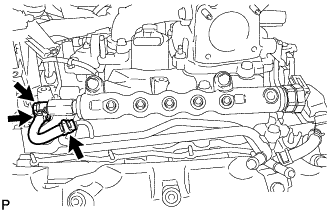
REMOVE NO. 6 INJECTION PIPE SUB-ASSEMBLY
Note
After removing an injection pipe, to prevent dirt or foreign objects from entering the common rail holes, cover the holes with protective tape.
-
w/ EGR System:
-
Using a union nut wrench, loosen the No. 6 injection pipe ends.
-
Remove the 2 nuts and 2 No. 2 injection pipe clamps.
-
Remove the No. 6 injection pipe.
-
-
w/o EGR System:
-
Using a union nut wrench, loosen the No. 6 injection pipe ends.
-
Remove the nut and No. 2 injection pipe clamp.
-
Remove the bolt and No. 6 injection pipe.
-
-
-
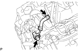
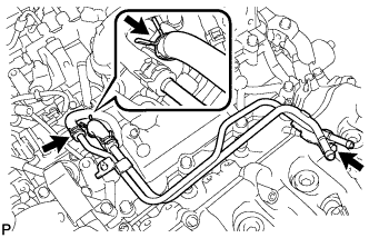
REMOVE NO. 1 VACUUM SWITCHING VALVE ASSEMBLY
-
Disconnect the 2 vacuum hoses.
-
Remove the bolt and vacuum switching valve.
-
-
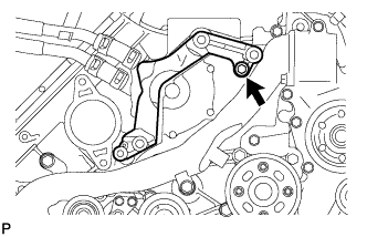
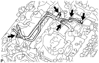
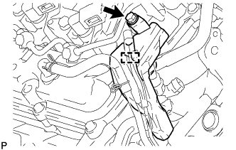
REMOVE NO. 1 VACUUM TRANSMITTING PIPE SUB-ASSEMBLY
-
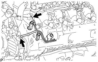
Disconnect the 2 vacuum hoses.
-
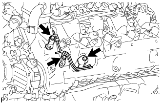
Remove the 3 bolts and vacuum transmitting pipe.
-
-
REMOVE CYLINDER HEAD COVER SILENCER LH
-
Remove the 4 bolts and cylinder head cover silencer.
-
-
REMOVE NO. 4 NOZZLE LEAKAGE PIPE
-
Disconnect the fuel hose.
-
Remove the fuel check valve, No. 4 nozzle leakage pipe and gasket.
-
-
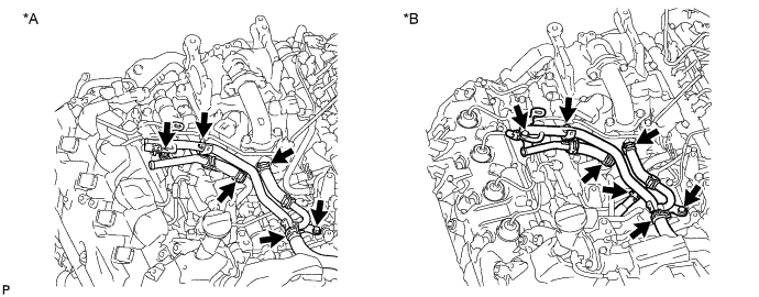
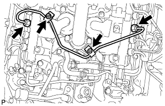
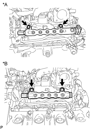
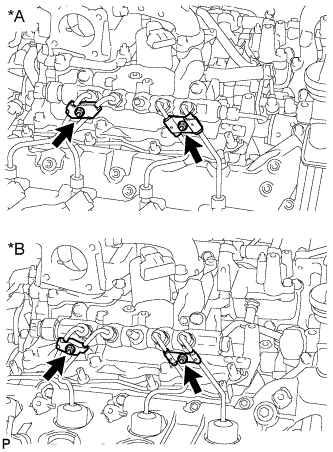
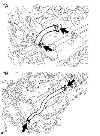
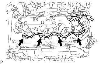
REMOVE INJECTION PIPE LH
-
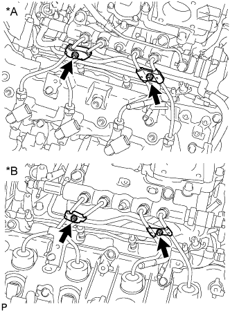
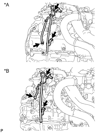
Text in Illustration *A w/ DPF *B w/o DPF w/ Intercooler:
Remove the 2 nuts and 4 injection pipe clamps.
-
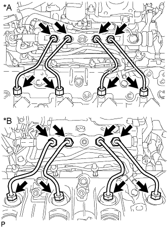
Text in Illustration *A w/ DPF *B w/o DPF Using a union nut wrench, remove the 4 injection pipes.
Note
After removing an injection pipe, to prevent dirt or foreign objects from entering the common rail holes or injector holes, cover the holes with protective tape.
-
-
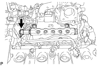
REMOVE NO. 2 FUEL PIPE
-
Remove the No. 4 fuel hose.
-
Remove the union bolt, gasket, bolt, and No. 2 fuel pipe.
-
-
REMOVE NO. 5 NOZZLE LEAKAGE PIPE
-
w/ DPF:
-
Disconnect the fuel hose.
-
Remove the union bolt, gasket and No. 5 nozzle leakage pipe.
-
-
w/o DPF:
Remove the union bolt, gasket and No. 5 nozzle leakage pipe.
-
-
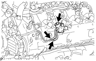
REMOVE COMMON RAIL ASSEMBLY LH
-
Text in Illustration *A w/ DPF *B w/o DPF Remove the 2 bolts and common rail.
Note
-
Do not remove the fuel pressure limiter from the common rail. If it is removed, replace the common rail.
-
w/ DPF:
Do not remove the pressure discharge valve from the common rail. If it is removed, replace the common rail.
-
-
-
REMOVE FUEL FILTER TO INJECTION PUMP FUEL PIPE SUB-ASSEMBLY
-
w/ DPF:
-
Remove the bolt and No. 2 injection pipe clamp.
-
Disconnect the fuel hose.
-
Remove the union bolt, nut, bolt, fuel filter to injection pump fuel pipe and gasket.
-
-
w/o DPF:
-
Disconnect the 2 hoses from the fuel pipe.
-
Remove the bolt and fuel filter to injection pump fuel pipe.
-
-
-
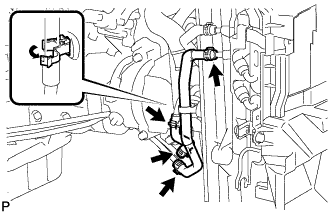
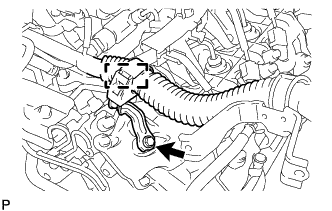
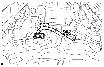
DISCONNECT NO. 2 ENGINE WIRE
-
Remove the 3 bolts and using a clip remover, detach the 2 wire harness clamps, and then disconnect the No. 2 engine wire.
-
-
REMOVE CYLINDER HEAD COVER SILENCER RH
-
Remove the 4 bolts and cylinder head cover silencer.
-
-
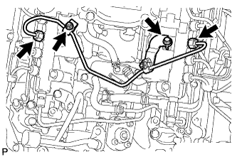
REMOVE INJECTION PIPE RH
-
Text in Illustration *A w/ DPF *B w/o DPF w/ Intercooler:
Remove the 2 nuts and 4 injection pipe clamps.
-
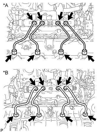
Text in Illustration *A w/ DPF *B w/o DPF Using a union nut wrench, remove the 4 injection pipes.
Note
After removing an injection pipe, to prevent dirt or foreign objects from entering the common rail holes or injector holes, cover the holes with protective tape.
-
-
REMOVE NO. 2 IDLER PULLEY (w/ Viscous Heater)
-
Remove the bolt, cover, No. 2 idler pulley and collar.
-
-
REMOVE NO. 2 IDLER PULLEY BRACKET (w/ Viscous Heater)
-
Remove the 3 bolts and idler pulley bracket.
-
-
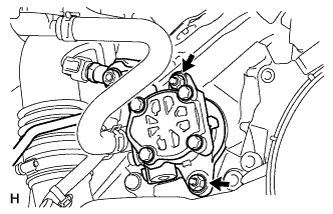
REMOVE VACUUM PUMP ASSEMBLY
-
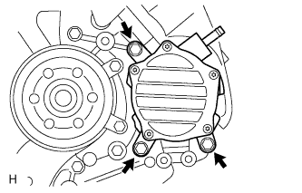
Remove the 3 bolts and vacuum pump.
-
Remove the 2 O-rings.
-
-
REMOVE CONNECTING WIRE
-
Detach the 2 clamps and remove the connecting wire.
-
-
REMOVE NO. 3 NOZZLE LEAKAGE PIPE
-
Remove the 2 injector hollow screws, 3 bolts, No. 3 nozzle leakage pipe and 2 gaskets.
-
-
REMOVE CYLINDER HEAD COVER INSULATOR RH
-
REMOVE NO. 2 VENTILATION HOSE
Text in Illustration *A w/ DPF *B w/o DPF -
REMOVE NO. 1 FUEL INJECTOR PROTECTOR
-
Remove the bolt and No. 1 fuel injector protector.
-
-
REMOVE NO. 1 NOZZLE LEAKAGE PIPE
-
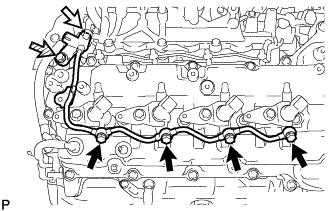
Remove the 4 injector hollow screws and 4 gaskets.
Text in Illustration 
Injector Hollow Screw 
No. 2 Check Valve 
Union Bolt -
Remove the No. 2 check valve from the fuel tube and No. 1 nozzle leakage pipe.
-
Remove the union bolt and No. 1 nozzle leakage pipe.
Note
-
When removing the nozzle leakage pipe, place a cushion under the pipe.
-
Be careful not to deform or scratch the union seal surface.
-
After removing the nozzle leakage pipe, put it in a plastic bag to prevent foreign matter from contaminating its injector inlet.
-
-
-
REMOVE FUEL INJECTOR RH
-
Remove the 4 bolts, 4 washers, 4 nozzle holder clamps and 4 injectors.
Tech Tips
Arrange the injectors, holder clamps, washers and bolts in the correct order.
-
Remove the O-ring from each injector.
-
Remove the 4 injection nozzle seats from the cylinder head.
-
-
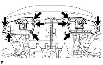
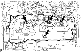
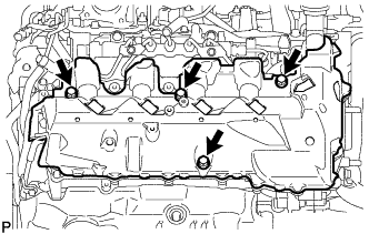
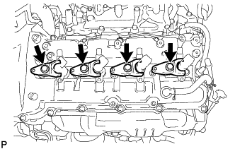
REMOVE CYLINDER HEAD COVER SUB-ASSEMBLY RH
-
Remove the 19 bolts, 4 nozzle holder clamp seats and cylinder head cover RH.
Text in Illustration Bolt Nozzle Holder Clamp Seat -
Remove the cylinder head cover gasket RH and No. 3 cylinder head cover gasket from the cylinder head cover RH.
-
-
REMOVE NO. 2 FUEL PUMP BRACKET
-
Remove the bolt and No. 2 fuel pump bracket.
-
-
REMOVE CYLINDER HEAD COVER INSULATOR LH
-
REMOVE NO. 3 VENTILATION HOSE
Text in Illustration *A w/ DPF *B w/o DPF -
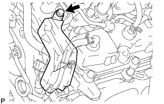
REMOVE BREATHER PLUG LH
-
Text in Illustration *A w/ DPF *B w/o DPF Disconnect the hose.
-
w/o DPF:
Detach the clamp.
-
Remove the breather plug LH.
-
-
REMOVE NO. 2 FUEL INJECTOR PROTECTOR
-
Detach the hose clamp.
-
Remove the bolt and No. 2 fuel injector protector.
-
-
REMOVE NO. 2 NOZZLE LEAKAGE PIPE
-
Remove the 4 injector hollow screws and 4 gaskets.
Text in Illustration Injector Hollow Screw Bolt -
Remove the 2 bolts and No. 2 nozzle leakage pipe.
Note
-
When removing the nozzle leakage pipe, place a cushion under the pipe.
-
Be careful not to deform or scratch the union seal surface.
-
After removing the nozzle leakage pipe, put it in a plastic bag to prevent foreign matter from contaminating its injector inlet.
-
-
-
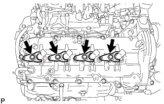
REMOVE FUEL INJECTOR LH
-
Remove the 4 bolts, 4 washers, 4 nozzle holder clamps and 4 injectors.
Tech Tips
Arrange the injectors, holder clamps, washers and bolts in the correct order.
-
Remove the O-ring from each injector.
-
Remove the 4 injection nozzle seats from the cylinder head.
-
-
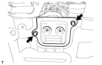
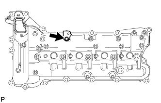
REMOVE OIL SEPARATOR ASSEMBLY
-
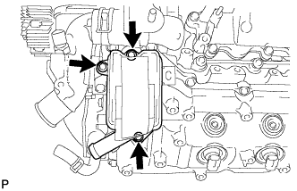
Remove the 3 bolts, oil separator and gasket.
-
-
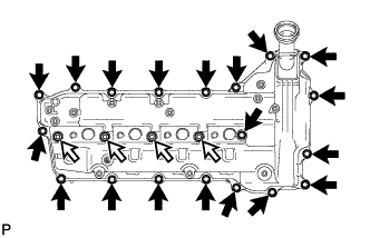
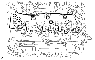
REMOVE CYLINDER HEAD COVER SUB-ASSEMBLY LH
-

Remove the 18 bolts, 4 nozzle holder clamp seats and cylinder head cover LH.
Text in Illustration Bolt Nozzle Holder Clamp Seat -
Remove the cylinder head cover gasket LH and No. 4 cylinder head cover gasket from the cylinder head cover LH.
-
-
REMOVE NO. 1 AND NO. 2 CAMSHAFTS
-
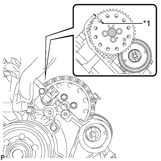
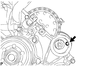
Text in Illustration *1 Arrow Rotate the crankshaft clockwise, and align the No. 1 camshaft timing sprocket arrow with the cylinder head upper surface.
-
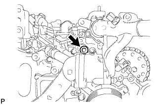
Using a 10 mm hexagon wrench, remove the taper screw plug.
-
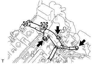
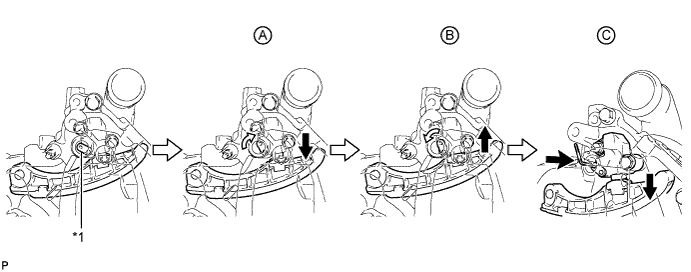
Fix the No. 1 chain tensioner in place.
-
Push the tensioner slipper away from the tensioner, and move the stopper plate clockwise to release the lock as shown in A.
-
Push down the tensioner slipper and move the stopper plate counterclockwise to set the lock as shown in B.
-
Push the tensioner slipper away from the tensioner, and insert a hexagon wrench into the stopper plate hole as shown in C.
Note
Do not drop the hexagon wrench into the engine.
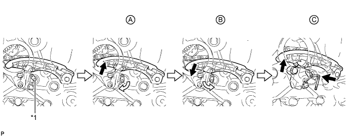
Text in Illustration *1 Stopper Plate - -
-
-
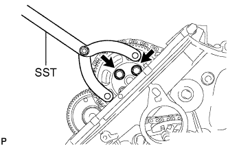
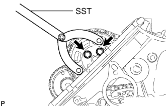
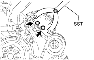
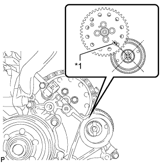
Using SST, hold the pump drive shaft gear.
- SST
- 09960-10010 ( 09962-01000, 09963-01000 )
-
Remove the 2 bolts.
-
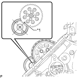
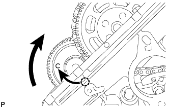
Text in Illustration *1 Arrow Rotate the crankshaft clockwise 360° so that the No. 1 camshaft timing sprocket arrow points at the No. 1 camshaft center.
Note
Do not rotate the crankshaft counterclockwise in order to align the sprocket arrow and camshaft center.
-
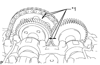
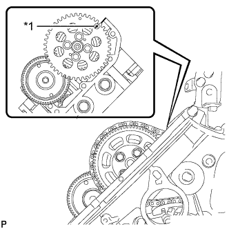
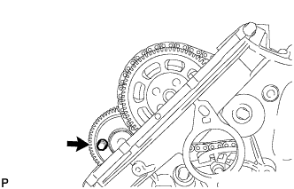
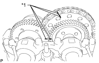
Text in Illustration *1 Matchmark Place matchmarks on the No. 1 timing chain and No. 1 camshaft timing sprocket.
-
Place matchmarks on the No. 1 and No. 2 camshaft gears.
-
Using SST, hold the pump drive shaft gear.
- SST
- 09960-10010 ( 09962-01000, 09963-01000 )
-
Remove the 2 bolts and pump drive shaft gear.
-
Disconnect the No. 1 timing chain and No. 1 camshaft timing sprocket from the No. 2 camshaft.
Note
-
Do not remove the No. 1 camshaft timing sprocket from the No. 1 timing chain.
-
Do not rotate the crankshaft until the No. 1 timing chain and No. 1 camshaft timing sprocket are connected to the No. 2 camshaft.
Tech Tips
If fixing the No. 1 camshaft timing sprocket in place, pass a rope or equivalent through one of the No. 1 camshaft timing sprocket holes and tie the sprocket and chain together.
-
-
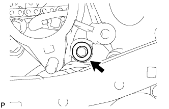
Turn the No. 1 camshaft clockwise so that the bolt is easier to install.
-
Using a 6 mm x 1.0 pitch service bolt with a length of 16 mm or more, fix the No. 1 camshaft in place.
- Torque:
- 8.0 N*m { 82 kgf*cm, 71 in.*lbf }
Note
Do not drop the bolt into the engine.
Tech Tips
If it is difficult to install the bolt, rotate the camshaft so that the bolt is easier to install.
-
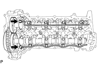
Loosen the 2 union bolts.
-
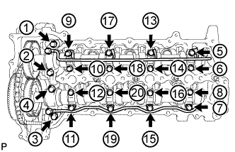
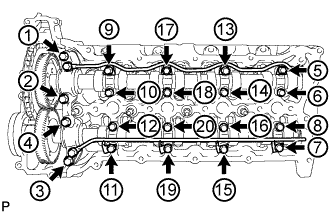
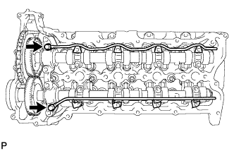
Uniformly loosen and remove the 20 bolts in the sequence shown in the illustration.
-
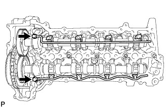
Remove the 2 union bolts and No. 1 and No. 2 oil feed pipes.
-
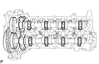
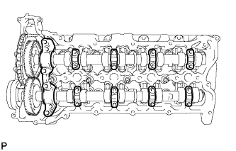
Remove the 8 No. 3 camshaft bearing caps and No. 1 camshaft bearing cap.
Tech Tips
Be sure to arrange the removed parts for each installation position separately.
-
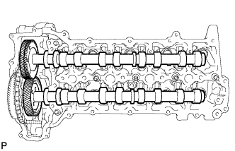
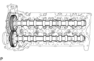
Remove the No. 1 and No. 2 camshafts.
-
-
REMOVE NO. 3 AND NO. 4 CAMSHAFTS
-
Text in Illustration *1 Arrow Rotate the crankshaft clockwise, and align the No. 2 camshaft timing sprocket arrow with the cylinder head upper surface.
-
Using a 10 mm hexagon wrench, remove the taper screw plug.
-
Fix the No. 2 chain tensioner in place.
-
Push the tensioner slipper away from the tensioner, and move the stopper plate clockwise to release the lock as shown in A.
-
Push up the tensioner slipper and move the stopper plate counterclockwise to set the lock as shown in B.
-
Push the tensioner slipper away from the tensioner, and insert a hexagon wrench into the stopper plate hole as shown in C.
Note
Do not drop the hexagon wrench into the engine.
Text in Illustration *1 Stopper Plate - -
-
-
Using SST, hold the No. 2 camshaft timing sprocket.
- SST
- 09960-10010 ( 09962-01000, 09963-01000 )
-
Remove the 2 bolts.
-
Text in Illustration *1 Arrow Rotate the crankshaft clockwise 360° so that the No. 2 camshaft timing sprocket arrow points at the No. 4 camshaft center.
-
Text in Illustration *1 Matchmark Place matchmarks on the No. 2 timing chain and No. 2 camshaft timing sprocket.
-
Place matchmarks on the No. 3 and No. 4 camshaft gears.
-
Using SST, hold the No. 2 camshaft timing sprocket.
- SST
- 09960-10010 ( 09962-01000, 09963-01000 )
-
Remove the 2 bolts, and disconnect the No. 2 timing chain and No. 2 camshaft timing sprocket from the No. 3 camshaft.
Note
-
Do not remove the No. 2 camshaft timing sprocket from the No. 2 timing chain.
-
Do not rotate the crankshaft until the No. 2 timing chain and No. 2 camshaft timing sprocket are connected to the No. 3 camshaft.
Tech Tips
If fixing the No. 2 camshaft timing sprocket in place, pass a rope or equivalent through one of the No. 2 camshaft timing sprocket holes and tie the sprocket and chain together.
-
-
Using a 6 mm x 1.0 pitch service bolt with a length of 16 mm or more, fix the No. 4 camshaft in place.
- Torque:
- 8.0 N*m { 82 kgf*cm, 71 in.*lbf }
Note
Do not drop the bolt into the chain cover.
Tech Tips
If it is difficult to install the bolt, rotate the camshaft so that the bolt is easier to install.
-

Loosen the 2 union bolts.
-
Uniformly loosen and remove the 20 bolts in the sequence shown in the illustration.
-
Remove the 2 union bolts and No. 3 and No. 4 oil feed pipes.
-
Remove the 8 No. 3 camshaft bearing caps and No. 4 camshaft bearing cap.
Tech Tips
Be sure to arrange the removed parts for each installation position separately.
-
Remove the No. 3 and No. 4 camshafts.
-