w/ DPF:
When fuel lines are disconnected, air may enter the fuel lines, leading to engine starting trouble. Therefore, perform forced regeneration and bleed the air from the fuel lines (Click here).
- Click here
INSTALL FRONT ENGINE MOUNTING INSULATOR LH
-
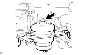
Install the mounting insulator with the nut.
80 N*m 816 kgf*cm 59 ft.*lbf
-
- Click here
INSTALL FRONT ENGINE MOUNTING INSULATOR RH
-
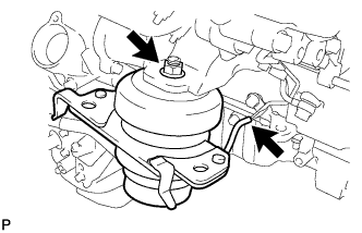
Install the mounting insulator with the nut.
80 N*m 816 kgf*cm 59 ft.*lbf -
Connect the vacuum hose.
-
- Click here
INSTALL NO. 1 AND NO. 2 ENGINE HANGER
-
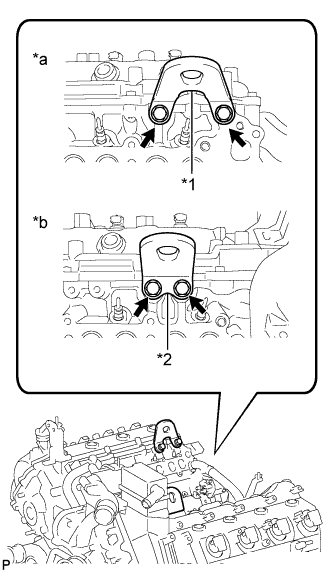
Install the No. 1 and No. 2 engine hangers to the cylinder head RH and LH with the 4 bolts as shown in the illustration.
25 N*m 250 kgf*cm 18 ft.*lbf Tip:No. 1 engine hanger 12281-51040 No. 2 engine hanger 12282-51040 Bolt 91671-80825 Table 1. Text in Illustration *1 No. 1 Engine Hanger *2 No. 2 Engine Hanger *a RH *b LH
-
- Click here
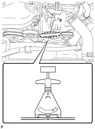
REMOVE ENGINE STAND
-
Attach an engine sling device and hang the engine with a chain block.
-
Lift the engine, and remove it from the engine stand.
Note:
-
With the exception of installing the engine assembly to an engine stand or removing the engine assembly from an engine stand, do not perform any work on the engine while it is suspended, as doing so is dangerous.
-
Pay attention to the angle of the sling device as the engine assembly or engine hangers may be damaged or deformed if the angle is incorrect.
-
-
- Click here
INSTALL DRIVE PLATE AND RING GEAR SUB-ASSEMBLY (for Automatic Transmission)
-
Using a wrench, hold the crankshaft.
-
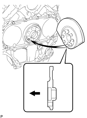
Install the rear crankshaft balancer weight.
Table 2. Text in Illustration 
Engine Side Tip:
-
Align the pin hole of the rear crankshaft balancer weight with the pin of the crankshaft.
-
As the rear crankshaft balancer weight is not reversible, be sure to install it so that it is facing in the direction shown in the illustration.
-
-
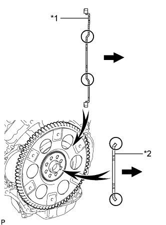
Install the drive plate and ring gear and rear drive plate spacer with 8 new bolts.
Table 3. Text in Illustration *1 Drive Plate and Ring Gear *2 Rear Drive Plate Spacer Automatic Transmission Side Tip:As the drive plate and ring gear and rear drive plate spacer are not reversible, be sure to install them so that they are facing in the direction shown in the illustration.
-
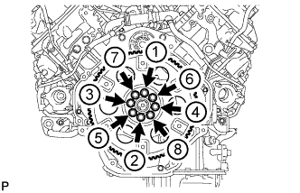
Install and uniformly tighten the 8 bolts in the sequence shown in the illustration.
182 N*m 1856 kgf*cm 134 ft.*lbf
-
- Click here
INSTALL FLYWHEEL SUB-ASSEMBLY (for Manual Transmission)
-
Temporarily install the flywheel with 8 new bolts.
Note:
-
Align the crankshaft knock pin and flywheel knock pin hole.
-
Do not strike or damage the flywheel installation bolts. Be sure to handle them carefully.
-
Make sure there is no oil on the bolts.
-
-
Using a wrench, hold the crankshaft.
-
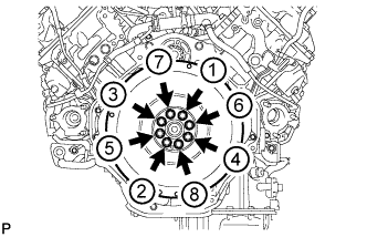
Uniformly install and tighten the 8 bolts in the sequence shown in the illustration.
182 N*m 1856 kgf*cm 134 ft.*lbf
-
-
Click here
INSTALL CLUTCH DISC ASSEMBLY (for Manual Transmission)
-
Insert SST into the clutch disc, then insert the clutch disc into the flywheel.
09301-00120 Note:Take care not to insert the clutch disc in the wrong direction.
-
-
Click here
INSTALL CLUTCH COVER ASSEMBLY (for Manual Transmission)
-
Align the matchmark on the clutch cover with the one on the flywheel.
-
In the order shown in the illustration, temporarily install the 8 bolts starting from the bolt located near the knock pin on the top.
-
Check that the disc is in the center by lightly moving SST up and down, and left and right.
09301-00120 -
Evenly tighten the bolts by following the order shown in the illustration.
39 N*m 400 kgf*cm 29 ft.*lbf
-
- Click here
INSTALL ENGINE ASSEMBLY
-
Slowly lower the engine into the engine compartment.
-
Install the 4 bolts to the front mounting insulator RH and LH.
58 N*m 591 kgf*cm 43 ft.*lbf -
Remove the 4 bolts and No. 1 and No. 2 engine hangers.
-
- Click here
INSTALL CLUTCH RELEASE CYLINDER TO FLEXIBLE HOSE TUBE (for Manual Transmission)
-
Install the clutch release cylinder to flexible hose tube with the bolt.
20 N*m 204 kgf*cm 15 ft.*lbf
-
- Click here
INSTALL MANUAL TRANSMISSION UNIT ASSEMBLY
- Click here
INSTALL AUTOMATIC TRANSMISSION ASSEMBLY
- Click here
INSTALL NO. 2 INTAKE MANIFOLD
-
Install a new gasket and the No. 2 intake manifold with the 9 bolts.
21 N*m 214 kgf*cm 15 ft.*lbf
-
- Click here
INSTALL NO. 1 INTAKE MANIFOLD
-
Install a new gasket and the No. 1 intake manifold with the 9 bolts.
21 N*m 214 kgf*cm 15 ft.*lbf
-
- Click here
INSTALL NO. 1 FUEL PIPE CLAMP (w/ DPF)
-
Install the 2 No. 1 fuel pipe clamps with the 2 bolts.
10 N*m 102 kgf*cm 7 ft.*lbf
-
- Click here
INSTALL FUEL HOSE BRACKET (w/ DPF)
-
Install the fuel hose bracket with the bolt.
21 N*m 214 kgf*cm 15 ft.*lbf
-
- Click here
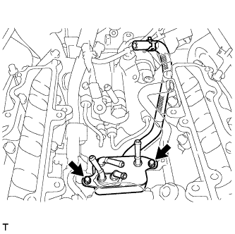
INSTALL NO. 1 NOZZLE LEAKAGE PIPE (w/ DPF)
-
Tighten the union bolt and 4 injector hollow screws.
for union bolt 21 N*m 214 kgf*cm 15 ft.*lbf for injector hollow screw 18 N*m 184 kgf*cm 13 ft.*lbf -
Install the fuel tube and No. 1 nozzle leakage pipe with the check valve and new gasket.
32 N*m 321 kgf*cm 23 ft.*lbf
-
- Click here
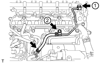
INSTALL NO. 2 NOZZLE LEAKAGE PIPE (w/ DPF)
-
Tighten the 4 injector hollow screws and 2 bolts.
for injector hollow screw 18 N*m 184 kgf*cm 13 ft.*lbf for bolt 10 N*m 102 kgf*cm 7 ft.*lbf
-
- Click here
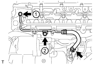
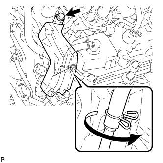
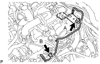
INSTALL NO. 1 WATER BY-PASS PIPE
-
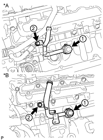
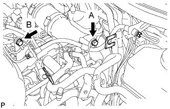
Temporarily install a new gasket and the No. 1 water by-pass pipe with the union bolt and bolt.
Table 4. Text in Illustration *A w/ DPF *B w/o DPF -
Tighten the union bolt and bolt in the order shown in the illustration.
for union bolt 59 N*m 600 kgf*cm 43 ft.*lbf for bolt 10 N*m 102 kgf*cm 7 ft.*lbf
-
- Click here
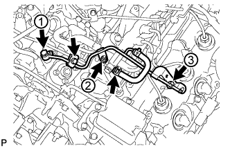
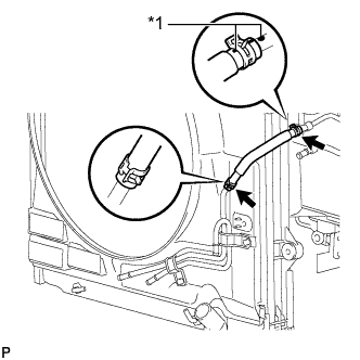
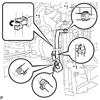
INSTALL FUEL TUBE SUB-ASSEMBLY (w/ DPF)
-
Attach the 3 clamps to install the fuel tube.
-
Connect the 3 fuel tube connectors (Click here).
-
- Click here
INSTALL FUEL COOLER ASSEMBLY (w/o DPF)
-
Install the fuel cooler with the 2 bolts.
10 N*m 102 kgf*cm 7 ft.*lbf
-
- Click here
CONNECT NO. 6 WATER BY-PASS HOSE (w/o DPF)
- Click here
INSTALL NO. 4 NOZZLE LEAKAGE PIPE (w/o DPF)
-
Temporarily install a new gasket and the No. 4 nozzle leakage pipe with the union bolt and bolt.
-
Tighten the union bolt and bolt in the order shown in the illustration.
for union bolt 21 N*m 214 kgf*cm 15 ft.*lbf for bolt 10 N*m 102 kgf*cm 7 ft.*lbf -
Connect the No. 2 fuel hose to the fuel cooler.
-
- Click here
INSTALL NO. 3 NOZZLE LEAKAGE PIPE (w/o DPF)
-
Temporarily install a new gasket and the No. 3 nozzle leakage pipe with the union bolt and bolt.
-
Tighten the union bolt and bolt in the order shown in the illustration.
for union bolt 21 N*m 214 kgf*cm 15 ft.*lbf for bolt 10 N*m 102 kgf*cm 7 ft.*lbf -
Connect the No. 1 fuel hose to the fuel cooler.
-
- Click here
INSTALL EGR COOLER INSULATOR (w/ EGR System)
- Click here
INSTALL EGR VALVE ASSEMBLY WITH EGR COOLER (w/ EGR System)
-
Connect the No. 5 water by-pass hose to the water by-pass outlet.
-
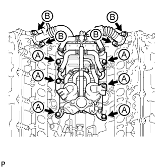
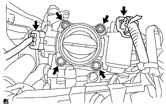
Install 2 new gaskets and the EGR valve with EGR cooler with the 6 bolts labeled A and 4 bolts labeled B shown in the illustration.
for bolt A 21 N*m 214 kgf*cm 15 ft.*lbf for bolt B 29 N*m 296 kgf*cm 21 ft.*lbf Tip:The gasket claws should face toward the No. 1 and No. 2 EGR pipes.
-
- Click here
INSTALL EGR PIPE INSULATOR (w/ EGR System)
-
Install the EGR pipe insulator with the 2 bolts.
21 N*m 214 kgf*cm 15 ft.*lbf Note:If the No. 1 and No. 2 EGR pipe insulator installation stay is deformed, or the bolt holes of the EGR pipe insulator do not align, replace the No. 1 and No. 2 EGR pipes as a set.
-
- Click here
INSTALL INTAKE MANIFOLD INSULATOR (w/ EGR System)
-
Click here
INSTALL NO. 3 INTAKE MANIFOLD
-
Install 2 new gaskets to the No. 1 and No. 2 intake manifolds.
-
Install the No. 3 intake manifold with the 16 bolts.
21 N*m 214 kgf*cm 15 ft.*lbf Table 5. Bolt Length Item Length Bolt A 25 mm (0.984 in.) Bolt B 70 mm (2.76 in.)
-
- Click here
CONNECT NO. 2 ENGINE WIRE
-

Connect the No. 2 engine wire with the 3 bolts.
for bolt A 13 N*m 133 kgf*cm 10 ft.*lbf for bolt B 32 N*m 326 kgf*cm 24 ft.*lbf -
Attach the 2 wire harness clamps.
-
- Click here
INSTALL INTAKE PIPE
-
w/ EGR System:
Install 2 new gaskets and the intake pipe with the 6 bolts and 2 nuts.
21 N*m 214 kgf*cm 15 ft.*lbf -
w/o EGR System:
Install a new gasket and the intake pipe with the 4 bolts and 2 nuts.
21 N*m 214 kgf*cm 15 ft.*lbf
-
- Click here
INSTALL NO. 3 NOZZLE LEAKAGE PIPE (w/ DPF)
-
Temporarily install 2 new gaskets and the No. 3 nozzle leakage pipe with the 2 injector hollow screws and 3 bolts.
-
Tighten the 2 injector hollow screws and 3 bolts.
for injector hollow screw 21 N*m 214 kgf*cm 15 ft.*lbf for bolt 21 N*m 214 kgf*cm 15 ft.*lbf Tip:Tighten the injector hollow screws first, and then tighten the bolts.
-
- Click here
INSTALL CONNECTING WIRE (w/ DPF)
-
Attach the 2 clamps to install the connecting wire.
-
- Click here
INSTALL NO. 2 INTAKE MANIFOLD INSULATOR (w/ Intercooler)
- Click here
INSTALL NO. 1 INTAKE MANIFOLD INSULATOR (w/ Intercooler)
- Click here
INSTALL COMMON RAIL ASSEMBLY RH
-
Install the common rail with the 2 bolts.
21 N*m 214 kgf*cm 15 ft.*lbf
-
- Click here
INSTALL INJECTION PIPE RH
-
Using a union nut wrench, install 4 new injection pipes.
34 N*m 347 kgf*cm 25 ft.*lbf Note:
-
Make sure there is no damage or foreign matter on the seal surfaces.
-
Use the formula to calculate special torque values for situations where a union nut wrench is combined with a torque wrench (Click here).
-
-
w/ Intercooler:
Install the 4 injection pipe clamps with the 2 nuts.
5.0 N*m 51 kgf*cm 44 in.*lbf
-
- Click here
INSTALL NO. 1 PROTECTOR FUEL INJECTOR (w/ DPF)
-
Install the No. 1 fuel injector protector with the bolt.
10 N*m 102 kgf*cm 7 ft.*lbf Tip:Press the ventilation hose clip against the No. 1 fuel injector protector as shown in the illustration.
-
- Click here
INSTALL NO. 2 PROTECTOR FUEL INJECTOR (w/ DPF)
-
Install the No. 2 fuel injector protector with the bolt.
10 N*m 102 kgf*cm 7 ft.*lbf Tip:Press the ventilation hose clip against the No. 2 fuel injector protector as shown in the illustration.
-
Attach the hose clamp.
-
- Click here
INSTALL CYLINDER HEAD COVER SILENCER RH (w/ DPF)
- Click here
INSTALL NO. 5 INJECTION PIPE SUB-ASSEMBLY
-
Temporarily install a new No. 5 injection pipe by hand.
Note:Make sure there is no damage or foreign matter on the seal surfaces.
-

w/ DPF:
Temporarily install the used gasket and fuel filter to injection pump fuel pipe with the nut, bolt and union bolt.
-

w/o DPF:
Temporarily install the used gasket and No. 2 fuel pipe with the nut, bolt and union bolt.
-

Install the No. 2 injection pipe clamp with the bolt.
5.0 N*m 51 kgf*cm 44 in.*lbf Table 6. Text in Illustration *A w/ DPF *B w/o DPF -
Using a union nut wrench, tighten the No. 5 injection pipe ends.
34 N*m 347 kgf*cm 25 ft.*lbf Note:Use the formula to calculate special torque values for situations where a union nut wrench is combined with a torque wrench (Click here).
-
Remove the bolt and No. 2 injection pipe clamp.
-
Remove the union bolt and gasket.
-
w/ DPF:
Remove the bolt, nut and fuel filter to injection pump fuel pipe.
-
w/o DPF:
Remove the bolt, nut and No. 2 fuel pipe.
-
- Click here
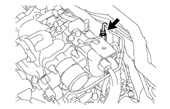
CONNECT FUEL PUMP MOTOR WIRE
-
Install the fuel pump motor wire bracket to the No. 3 intake manifold with the bolt.
10 N*m 102 kgf*cm 7 ft.*lbf -
Connect the connector to the fuel supply pump.
-
- Click here
INSTALL FUEL FILTER TO INJECTION PUMP FUEL PIPE SUB-ASSEMBLY
-
w/ DPF:
Note:Check for damage and foreign matter on the fuel pipe installation surface of the fuel supply pump.
If there is foreign matter, remove it from the installation surface.
If the installation surface is damaged, replace the fuel supply pump.
-
Temporarily install a new gasket and fuel filter to injection pump fuel pipe with the nut, bolt and union bolt.
-
Install the No. 2 injection pipe clamp with the bolt.
4.0 N*m 41 kgf*cm 35 in.*lbf -
Tighten the union bolt, bolt and nut.
for union bolt 12 N*m 125 kgf*cm 9 ft.*lbf for bolt and nut 10 N*m 102 kgf*cm 7 ft.*lbf -
Connect the fuel hose.
-
-
w/o DPF:
-
Install the fuel filter to injection pump fuel pipe with the bolt.
10 N*m 102 kgf*cm 7 ft.*lbf -
Connect the 2 hoses to the fuel pipe.
-
-
- Click here
INSTALL COMMON RAIL ASSEMBLY LH
-
Install the common rail with the 2 bolts.
21 N*m 214 kgf*cm 15 ft.*lbf
-
- Click here
INSTALL NO. 5 NOZZLE LEAKAGE PIPE (w/ DPF)
-
Install a new gasket and the leakage pipe with the union bolt.
29 N*m 296 kgf*cm 21 ft.*lbf Note:Make sure there is no foreign matter or damage on the seal surface.
-
w/ DPF:
Connect the fuel hose.
-
- Click here
INSTALL INJECTION PIPE LH
-
Using a union nut wrench, install the 4 new injection pipes.
34 N*m 347 kgf*cm 25 ft.*lbf Note:
-
Make sure there is no damage or foreign matter on the seal surfaces.
-
Use the formula to calculate special torque values for situations where a union nut wrench is combined with a torque wrench (Click here).
-
-
w/ Intercooler:
Install the 4 injection pipe clamps with the 2 nuts.
5.0 N*m 51 kgf*cm 44 in.*lbf
-
- Click here
INSTALL NO. 4 NOZZLE LEAKAGE PIPE (w/ DPF)
-
Temporarily install a new gasket and No. 4 nozzle leakage pipe with the fuel check valve.
-
Tighten the fuel check valve.
32 N*m 321 kgf*cm 23 ft.*lbf -
Connect the fuel hose.
-
- Click here
INSTALL CYLINDER HEAD COVER SILENCER LH (w/ DPF)
- Click here
INSTALL NO. 1 VACUUM TRANSMITTING PIPE SUB-ASSEMBLY (w/ DPF)
-
Install the vacuum transmitting pipe with the 3 bolts.
6.0 N*m 61 kgf*cm 53 in.*lbf -
Connect the 2 vacuum hoses.
-
- Click here
INSTALL NO. 1 VACUUM SWITCHING VALVE ASSEMBLY (w/ DPF)
-
Install the vacuum switching valve with the bolt.
6.0 N*m 61 kgf*cm 53 in.*lbf -
Connect the 2 vacuum hoses.
-
- Click here
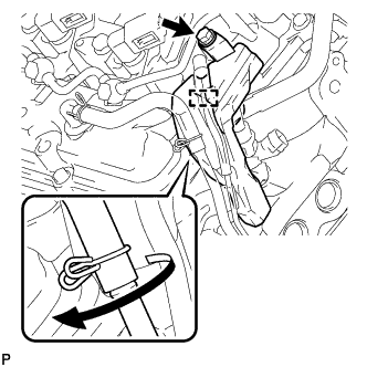
INSTALL NO. 2 FUEL PIPE SUB-ASSEMBLY (w/o DPF)
Note:Check for damage and foreign matter on the fuel pipe installation surface of the supply pump.
If there is foreign matter, remove it from the installation surface. If the installation surface is damaged, replace the fuel supply pump.
-
Temporarily install a new gasket and the No. 2 fuel pipe with the union bolt, nut and bolt.
-
Tighten the union bolt, nut and bolt in the order shown in the illustration.
for union bolt 25 N*m 255 kgf*cm 18 ft.*lbf for bolt and nut 10 N*m 102 kgf*cm 7 ft.*lbf -
Install the No. 2 injection pipe clamp with the bolt.
4.0 N*m 41 kgf*cm 35 in.*lbf -
Connect the fuel hose to the No. 5 nozzle leakage pipe.
-
- Click here
CONNECT NO. 6 INJECTION PIPE SUB-ASSEMBLY
-
w/ EGR System:
-
Temporarily install a new No. 6 injection pipe to the common rail LH and RH.
Note:Make sure there is no damage or foreign matter on the seal surfaces.
-
Install the 2 No. 2 injection pipe clamps with the 2 nuts.
5.0 N*m 51 kgf*cm 44 in.*lbf -
Using a union nut wrench, tighten the No. 6 injection pipe ends.
34 N*m 347 kgf*cm 25 ft.*lbf Note:Use the formula to calculate special torque values for situations where a union nut wrench is combined with a torque wrench (Click here).
-
-
w/o EGR System:
-
Temporarily install a new No. 6 injection pipe to the common rail LH and RH.
Note:Make sure there is no damage or foreign matter on the seal surfaces.
-
Install the bracket to the No. 3 intake manifold with the bolt.
10 N*m 102 kgf*cm 7 ft.*lbf -
Install the No. 2 injection pipe clamp with the nut.
5.0 N*m 51 kgf*cm 44 in.*lbf -
Using a union nut wrench, tighten the No. 6 injection pipe ends.
34 N*m 347 kgf*cm 25 ft.*lbf Note:Use the formula to calculate special torque values for situations where a union nut wrench is combined with a torque wrench (Click here).
-
-
- Click here
CONNECT ENGINE WIRE
-
Rear Side:
-
Install the glow plug wire harness with the nut and screw grommet.
4.0 N*m 41 kgf*cm 35 in.*lbf -
w/ DPF:
Connect the 3 connectors.
-
w/o DPF:
Connect the connector.
-
Install the engine wire harness protector with the 2 bolts.
-
Install the 2 ground wires with the 2 bolts.
8.4 N*m 86 kgf*cm 74 in.*lbf
-
-
LH Side:
-
Install the engine wire protector with the 2 bolts.
-
Connect the 8 connectors.
-
Attach the wire harness clamp.
-
Install the engine wire harness bracket with the bolt.
-
for RHD:
Connect the wire harness with the wire harness clamp holder.
-
Attach the 3 wire harness clamps and connect the 2 connectors.
-
w/ DPF:
Connect the 7 connectors to the injection driver.
-
w/o DPF:
Connect the 4 connectors to the injection driver.
-
Install the ground wire with the bolt.
8.4 N*m 86 kgf*cm 74 in.*lbf -
Connect the wire harness holder to the relay block.
-
Connect the 4 connectors to the relay block.
-
Connect the wire harness with the wire harness clamp holder.
-
for RHD:
Connect the wire harness with the wire harness clamp holder.
-
for RHD:
Connect the ECM connector to the ECM.
-
for RHD:
Attach the wire harness tab to the relay block.
-
Connect the 4 connectors to the relay block.
-
Connect the generator positive (+) cable to the body panel with the 2 clamps.
-
Attach the generator positive (+) cable holder to the relay block, and install the cable to the relay block with the nut.
10 N*m 102 kgf*cm 7 ft.*lbf -
Connect the wire harness with the wire harness clamp holder, and attach the ground wire clamp to the relay block side.
-
Install the ground wire to the body panel with the bolt.
8.4 N*m 86 kgf*cm 74 in.*lbf
-
-
RH Side:
-
w/ Winch:
Install the ground wire with the bolt.
19 N*m 194 kgf*cm 14 ft.*lbf -
Install the engine wire harness protector with the 3 bolts.
-
Connect the 7 connectors.
-
Install the wire harness bracket with the bolt.
-
Install the glow plug wire harness with the nut and screw grommet.
4.0 N*m 41 kgf*cm 35 in.*lbf -
for RHD:
Install the wire harness holder with the bolt.
-
for RHD:
Connect the wire harness with the wire harness holder.
-
for LHD:
Connect the wire harness with the wire harness clamp holder.
-
for LHD:
Connect the ECM connector to the ECM.
-
for LHD:
Attach the wire harness tab to the relay block.
-
for LHD:
Connect the 4 connectors to the relay block.
-
-
- Click here
INSTALL NO. 4 WATER BY-PASS PIPE
-
w/ EGR System:
-
w/ DPF:
Connect the 3 water hose ends, and temporarily install the No. 4 water by-pass pipe with the 2 bolts and nut.
-
w/o DPF:
Connect the 4 water hose ends, and temporarily install the No. 4 water by-pass pipe with the 2 bolts and nut.
-
-
w/o EGR System:
Connect the 3 water hose ends, and temporarily install the No. 4 water by-pass pipe with the 2 bolts and nut.
-
First tighten the 2 bolts and then tighten the nut.
10 N*m 102 kgf*cm 7 ft.*lbf
-
- Click here
INSTALL NO. 3 WATER BY-PASS PIPE (w/o Viscous Heater)
-
Connect the 2 water hose ends, and install the No. 3 water by-pass pipe with the 2 bolts.
10 N*m 102 kgf*cm 7 ft.*lbf
-
- Click here
CONNECT FUEL HOSE
- Click here
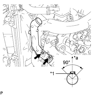
INSTALL NO. 1 AIR CLEANER PIPE SUB-ASSEMBLY
-
Connect the No. 1 air cleaner pipe to the No. 1 intake air connector pipe.
-
Install the pipe with the bolt.
21 N*m 214 kgf*cm 15 ft.*lbf -
Tighten the hose clamp.
6.3 N*m 64 kgf*cm 56 in.*lbf
-
- Click here
INSTALL HEATER WATER PIPE SUB-ASSEMBLY (w/ Viscous Heater)
-
Connect the 4 water hose ends, and install the water pipe with the 4 bolts.
9.8 N*m 100 kgf*cm 87 in.*lbf
-
- Click here
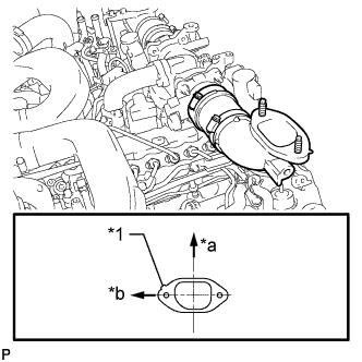
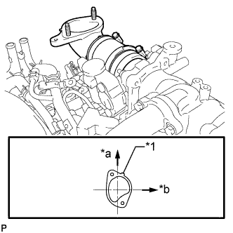
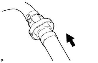
INSTALL NO. 2 INTAKE AIR CONNECTOR PIPE
-
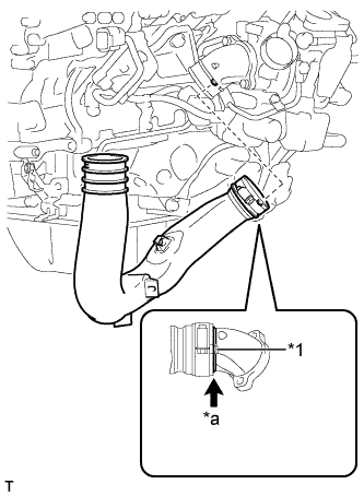
Install the No. 2 intake air connector pipe to the No. 2 inlet compressor elbow.
Table 7. Text in Illustration *1 Hose Stopper *a No Gap Note:Make sure there is no gap between the air pipe and hose stopper on the elbow side.
-
Install the bolt of the No. 2 intake air connector pipe.
21 N*m 214 kgf*cm 15 ft.*lbf Note:Do not excessively pull the air pipe towards the front of the engine.
-
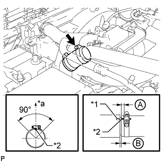
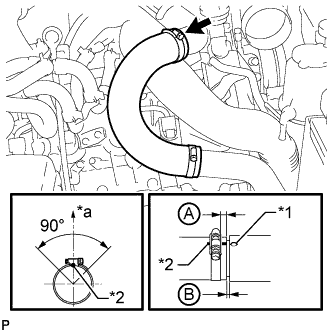
Tighten the hose clamp on the elbow side.
6.0 N*m 61 kgf*cm 53 in.*lbf Tip: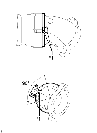
-
Align the 2 protrusions of the air pipe and elbow.
-
Install the air pipe so that the protrusion on the pipe side is within the range of the protrusion on the elbow side.
-
After tightening, a gap between the air pipe and hose stopper on the elbow side is acceptable.
-
Make sure the direction of the hose clamp is as shown in the illustration.
Table 8. Text in Illustration *1 Protrusion -
-
w/ Intercooler:
Connect the vacuum hose.
-
- Click here
ADJUST COMPRESSOR OIL
-
When replacing the compressor and magnetic clutch with a new one, gradually discharge the refrigerant gas from the service valve, and drain the following amount of oil from the new compressor and magnetic clutch before installation.
Standard VDJ200L-GNMNZV, GNTNZV, GPMNZV (Oil capacity inside the new compressor and magnetic clutch: 140 + 15 cc (4.7 + 0.51 fl.oz.)) - (Remaining oil amount in the removed compressor and magnetic clutch) = (Oil amount to be removed from the new compressor when replacing) Except VDJ200L-GNMNZV, GNTNZV, GPMNZV (Oil capacity inside the new compressor and magnetic clutch: 135 + 15 cc (4.6 + 0.51 fl.oz.)) - (Remaining oil amount in the removed compressor and magnetic clutch) = (Oil amount to be removed from the new compressor when replacing) Note:
-
When checking the compressor oil level, follow the A/C system precautions.
-
If a new compressor and magnetic clutch is installed without removing some oil remaining in the pipes of the vehicle, the oil amount will be too large. This prevents heat exchange in the refrigerant cycle and causes refrigerant failure.
-
If the volume of oil remaining in the removed compressor and magnetic clutch is too small, check for oil leakage.
-
Be sure to use ND-OIL 8 or equivalent for compressor oil.
-
-
- Click here
INSTALL COOLER COMPRESSOR ASSEMBLY
-
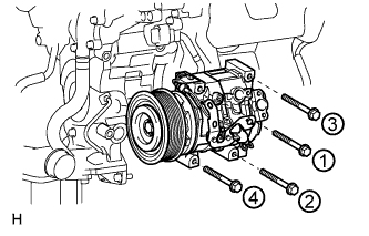
Temporarily install the cooler compressor with the 4 bolts.
-
Tighten the 4 bolts in the order shown in the illustration.
25 N*m 250 kgf*cm 18 ft.*lbf -
Attach the 3 wire harness clamps and connect the 4 connectors.
-
- Click here
INSTALL SUCTION HOSE SUB-ASSEMBLY
-
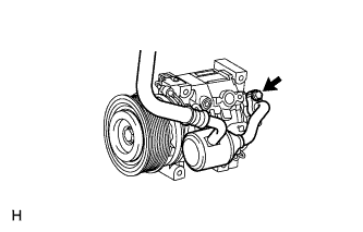
Remove the attached vinyl tape from the cooler refrigerant suction hose.
-
Sufficiently apply compressor oil to a new O-ring and the fitting surface of the cooler compressor.
Compressor oil ND-OIL 8 or equivalent -
Install the O-ring to the suction hose.
-
Connect the suction hose to the cooler compressor with the bolt.
9.8 N*m 100 kgf*cm 87 in.*lbf
-
-
Click here
INSTALL NO. 1 COOLER REFRIGERANT DISCHARGE HOSE
-
Remove the attached vinyl tape from the discharge hose.
-
Sufficiently apply compressor oil to a new O-ring and the fitting surface of the cooler compressor.
Compressor oil ND-OIL 8 or equivalent -
Install the O-ring to the discharge hose.
-
Connect the discharge hose to the cooler compressor with the bolt.
9.8 N*m 100 kgf*cm 87 in.*lbf
-
- Click here
INSTALL NO. 2 AIR CLEANER PIPE SUB-ASSEMBLY
-
Connect the No. 2 air cleaner pipe to the No. 2 intake air connector pipe.
-
Connect the ventilation hose to the oil separator.
-
Install the pipe with the bolt.
21 N*m 214 kgf*cm 15 ft.*lbf -
Tighten the hose clamp.
6.3 N*m 64 kgf*cm 56 in.*lbf
-
- Click here
INSTALL NO. 2 AIR TUBE ASSEMBLY
-
Apply a light coat of washer fluid to a new O-ring, and install it to the No. 2 air tube.
-
Install the No. 2 air tube with the bolt.
21 N*m 214 kgf*cm 15 ft.*lbf
-
- Click here
INSTALL NO. 4 AIR TUBE
-
Install the No. 4 air tube with the bolt.
21 N*m 214 kgf*cm 15 ft.*lbf Table 9. Text in Illustration *1 Paint Mark *a Top -
Tighten the hose clamp.
6.3 N*m 64 kgf*cm 56 in.*lbf Tip:Make sure the direction of the hose clamp is as shown in the illustration.
-
Install the suction hose with the bolt.
9.8 N*m 100 kgf*cm 87 in.*lbf
-
- Click here
INSTALL NO. 2 AIR HOSE
-

Connect the No. 2 air hose with the hose clamp.
6.3 N*m 64 kgf*cm 56 in.*lbf Table 10. Text in Illustration *1 Protrusion *2 Paint Mark *a Top Tip:
-
Align the paint mark of the air hose with the protrusion and push on the air hose so that distance B is 0 to 3 mm (0 to 0.118 in.).
-
Position the clamp so that distance A is 2 to 6 mm (0.0787 to 0.236 in.).
-
Make sure the direction of the hose clamp is as shown in the illustration.
-
-
- Click here
INSTALL NO. 1 AIR TUBE ASSEMBLY
-
Apply a light coat of washer fluid to a new O-ring, and install it to the No. 1 air tube.
-
Install the No. 1 air tube with the bolt.
21 N*m 214 kgf*cm 15 ft.*lbf
-
- Click here
INSTALL NO. 3 AIR TUBE
-

Install the No. 3 air tube with the bolt.
21 N*m 214 kgf*cm 15 ft.*lbf Table 11. Text in Illustration *1 Paint Mark *a Top -
Tighten the hose clamp.
6.3 N*m 64 kgf*cm 56 in.*lbf Tip:Make sure the direction of the hose clamp is as shown in the illustration.
-
Install the wire harness bracket with the bolt.
-
Install the ground wire with the nut, and attach the wire harness clamp.
8.4 N*m 85 kgf*cm 74 in.*lbf
-
- Click here
INSTALL NO. 1 AIR HOSE
-

Connect the No. 1 air hose with the hose clamp.
6.3 N*m 64 kgf*cm 56 in.*lbf Table 12. Text in Illustration *1 Protrusion *2 Paint Mark *a Top Tip:
-
Align the paint mark of the air hose with the protrusion and push on the air hose so that distance B is 0 to 3 mm (0 to 0.118 in.).
-
Position the clamp so that distance A is 2 to 6 mm (0.0787 to 0.236 in.).
-
Make sure the direction of the hose clamp is as shown in the illustration.
-
-
- Click here
INSTALL DIESEL THROTTLE BODY ASSEMBLY LH
-
Install a new gasket to the intake pipe.
-
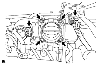
Install the throttle body with the 2 bolts and 2 nuts.
21 N*m 214 kgf*cm 15 ft.*lbf -
Connect the throttle position sensor connector.
-
Connect the throttle motor connector.
-
- Click here
INSTALL NO. 3 INTERCOOLER SUPPORT BRACKET
-
Install the No. 3 intercooler support bracket with the 2 bolts.
21 N*m 214 kgf*cm 15 ft.*lbf -

for Manual Transmission:
-
Connect the clutch tube to release cylinder 2 way with the bolt.
20 N*m 204 kgf*cm 15 ft.*lbf -
Check that the union nut is tightened to the specified torque.
15 N*m 154 kgf*cm 11 ft.*lbf Tip:Use the formula to calculate special torque values for situations where a union nut wrench is combined with a torque wrench (Click here).
-
-
- Click here
INSTALL NO. 1 GAS FILTER
-
Install the No. 1 gas filter.
-
Connect the hose to the intake pipe.
-
- Click here
INSTALL TUBE CONNECTOR TO FLEXIBLE HOSE TUBE (for Manual Transmission)
-
Temporarily install the flare nut of the tube connector to flexible hose tube to the clutch tube to release cylinder 2 way by hand.
-
Temporarily install the tube connector to flexible hose tube with the 2 bolts.
-
Tighten the bolt labeled A.
20 N*m 204 kgf*cm 15 ft.*lbf Note:Tighten the bolt labeled B after installing the clutch hose.
-
-
Click here
INSTALL AIR TUBE SUB-ASSEMBLY LH
-
Install the air tube to the throttle body.
-
Align the embossed mark of the throttle body with the paint mark of the No. 4 air hose.
-
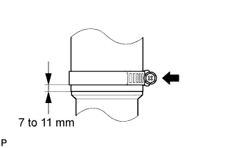
Tighten the hose clamp so that it is 7 to 11 mm (0.276 to 0.433 in.) from the end of the hose as shown in the illustration.
6.3 N*m 64 kgf*cm 56 in.*lbf
-
- Click here
INSTALL CLUTCH HOSE (for Manual Transmission)
-
Connect the clutch hose to the air tube with the bolt labeled A.
-
Temporarily install the clutch hose to the clutch master cylinder tube to flexible hose tube and tube connector to flexible hose tube, and fix it in place with the 2 clips.
20 N*m 204 kgf*cm 15 ft.*lbf -
Tighten the bolt labeled B.
20 N*m 204 kgf*cm 15 ft.*lbf -
Tighten the flexible hose tube.
Note:
-
Do not bend or damage the flexible hose tube.
-
Do not allow any foreign matter such as dirt and dust to enter the flexible hose tube from the connecting points.
Tip:
-
Use a torque wrench with a fulcrum length of 30 cm (11.8 in.). If using a torque wrench with a length that is not 30 cm (11.8 in.), calculate the torque specification for the torque wrench and SST based on the "without SST" torque specification (Click here).
-
Make sure union nut wrench and the wrench are connected in a straight line.
-
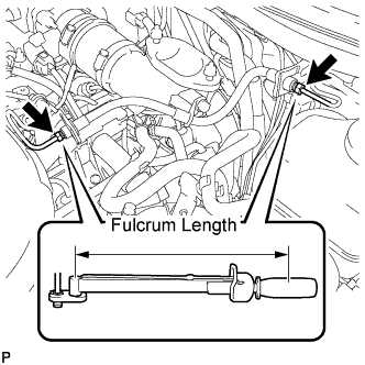
Using a 10 mm union nut wrench, tighten the 2 flare nuts of the flexible hose tube.
without union nut wrench 15 N*m 154 kgf*cm 11 ft.*lbf with union nut wrench 14 N*m 141 kgf*cm 10 ft.*lbf -
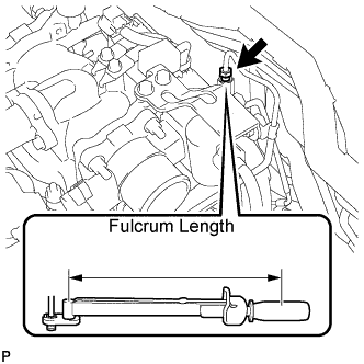
Using a 10 mm union nut wrench, tighten the flare nut of the flexible hose tube.
without union nut wrench 15 N*m 154 kgf*cm 11 ft.*lbf with union nut wrench 14 N*m 141 kgf*cm 10 ft.*lbf
-
-
- Click here
INSTALL DIESEL THROTTLE BODY ASSEMBLY RH
-
Install a new gasket to the intake pipe.
-
Install the throttle body with the 2 bolts and 2 nuts.
21 N*m 214 kgf*cm 15 ft.*lbf -
Connect the throttle position sensor connector.
-
Connect the throttle motor connector.
-
-
Click here
INSTALL AIR TUBE SUB-ASSEMBLY RH
-
Install the air tube to the throttle body.
-
Align the embossed mark of the throttle body with the paint mark of the No. 4 air hose.
-
Tighten the hose clamp so that it is 7 to 11 mm (0.276 to 0.433 in.) from the end of the hose as shown in the illustration.
6.3 N*m 64 kgf*cm 56 in.*lbf
-
- Click here
INSTALL NO. 2 ENGINE OIL LEVEL DIPSTICK GUIDE
-
Apply a light coat of engine oil to a new O-ring.
-
Install the O-ring to the No. 2 engine oil level dipstick guide.
-
Install the No. 2 engine oil level dipstick guide with the 2 bolts.
10 N*m 102 kgf*cm 7 ft.*lbf -
Connect the ventilation hose to the cylinder head cover RH.
-
Connect the wire harness clamp to the No. 2 engine oil level dipstick guide bracket.
-
- Click here
CONNECT WATER HOSE SUB-ASSEMBLY
- Click here
INSTALL NO. 2 COOL AIR INLET (w/o Intercooler)
-
Install a new gasket to the air tube LH.
Table 13. Text in Illustration *1 Protrusion *a Front *b LH Side Tip:Install the gasket with the protrusion facing as shown in the illustration.
-
Install the No. 2 cool air inlet with the 3 nuts and bolt.
21 N*m 214 kgf*cm 15 ft.*lbf -
Connect the No. 2 air hose to the No. 2 cool air inlet.
Table 14. Text in Illustration *1 Protrusion *2 Paint Mark *a Top -
Tighten the No. 2 air hose clamp.
6.3 N*m 64 kgf*cm 56 in.*lbf Tip:
-
Align the paint mark of the air hose with the protrusion and push on the air hose so that distance B is 0 to 3 mm (0 to 0.118 in.).
-
Position the clamp so that distance A is 2 to 6 mm (0.0787 to 0.236 in.).
-
Make sure the direction of the hose clamp is as shown in the illustration.
-
-
- Click here
INSTALL NO. 1 COOL AIR INLET (w/o Intercooler)
-
Install a new gasket to the air tube RH.
Table 15. Text in Illustration *1 Protrusion *a Front *b RH Side Tip:Install the gasket with the protrusion facing as shown in the illustration.
-
Install the No. 1 cool air inlet with the 3 nuts and bolt.
21 N*m 214 kgf*cm 15 ft.*lbf -
Connect the vacuum hose, intake air temperature sensor connector and turbo pressure sensor connector.
-
Connect the No. 1 air hose to the No. 1 cool air inlet.
Table 16. Text in Illustration *1 Protrusion *2 Paint Mark *a Top -
Tighten the No. 1 air hose clamp.
6.3 N*m 64 kgf*cm 56 in.*lbf Tip:
-
Align the paint mark of the air hose with the protrusion and push on the air hose so that distance B is 0 to 3 mm (0 to 0.118 in.).
-
Position the clamp so that distance A is 2 to 6 mm (0.0787 to 0.236 in.).
-
Make sure the direction of the hose clamp is as shown in the illustration.
-
-
- Click here
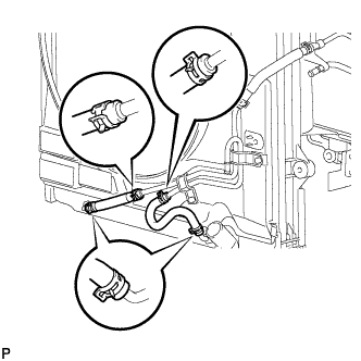
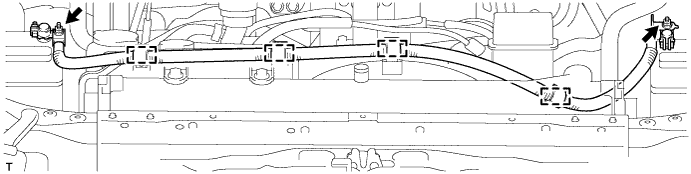
CONNECT FUEL TUBE
-
Install new No. 1 and No. 3 fuel tube clamps.
-
w/ DPF:
Connect the 2 fuel tubes to the clamps.
-
w/o DPF:
Connect the 3 fuel tubes to the clamps.
-
- Click here
CONNECT FRONT DIFFERENTIAL BREATHER TUBE
- Click here
ADD ENGINE OIL
-
Add fresh oil.
Standard Engine Oil Item Oil Grade Oil Viscosity (SAE) w/ DPF ACEA C2
(Using engine oil other than ACEA C2 may damage catalytic converter)
- 0W-30
- 5W-30
(0W-30 is best choice for fuel economy and good starting in cold weather)
w/o DPF G-DLD-1, API CF-4, API CF or ACEA B1
(You may also use API CE or CD)
- 5W-30
- 10W-30
- 15W-40
- 20W-50
(5W-30 is best choice for fuel economy and good starting in cold weather).
Standard Capacity Item Specified Condition Drain and refill with oil filter change 9.2 liters (9.7 US qts, 8.1 Imp. qts) Drain and refill without oil filter change 8.2 liters (8.7 US qts, 7.2 Imp. qts) Dry fill 9.9 liters (10.5 US qts, 8.7 Imp. qts) -
Install the oil filler cap.
-
- Click here
INSTALL RADIATOR ASSEMBLY
-
Install the radiator with the 4 bolts.
18 N*m 184 kgf*cm 13 ft.*lbf
-
- Click here
CONNECT RADIATOR SIDE DEFLECTOR LH
-
Install the side deflector with the 4 clips.
-
- Click here
CONNECT RADIATOR SIDE DEFLECTOR RH (for Manual Transmission)
-
Install the deflector with the 4 clips.
-
- Click here
INSTALL TRANSMISSION OIL COOLER AIR DUCT (for Automatic Transmission)
-
Install the oil cooler air duct with the 4 bolts.
4.9 N*m 50 kgf*cm 43 in.*lbf
-
- Click here
INSTALL FRONT BUMPER COVER
Tip:For the front bumper cover with garnish, use the procedure described below.
-
w/ Headlight Cleaner System:
Connect the headlight cleaner hose.
-
w/ TOYOTA Parking Assist-sensor System or w/ Fog Light:
Connect the No. 4 engine room wire connector.
-
Attach the 10 claws to install the front bumper cover.
-
Install the 3 clips, 4 screws and 4 bolts.
-
Using a T30 "TORX" socket, install the 6 screws.
-
- Click here
INSTALL RADIATOR GRILLE
-
w/ Wide View Front Monitor System:
-
Connect the connector.
-
-
Attach the 2 clips and 8 claws to install the radiator grille assembly.
-
Install the 3 screws.
-
- Click here
INSTALL FRONT BUMPER WINCH COVER (w/ Winch)
-
w/ Fog Light:
Connect the No. 4 engine room wire connector.
-
Connect the winch control wire connector and attach the 10 claws to install the front bumper cover.
-
Install the 3 clips, 4 screws and 4 bolts.
-
Using a T30 "TORX" socket, install the 6 screws.
-
- Click here
INSTALL FAN PULLEY
- Click here
INSTALL FAN SHROUD WITH FAN
-
Install the shroud together with the fluid coupling fan between the radiator and engine components.
Note:Be careful not to damage the radiator core.
-
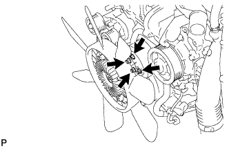
Temporarily install the fluid coupling fan to the fan bracket with the 4 nuts.
Tip:Tighten the nuts as much as possible by hand.
-
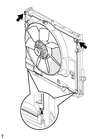
Attach the shroud claws to the radiator.
-
Install the shroud with the 2 bolts.
8.0 N*m 82 kgf*cm 71 in.*lbf -
Tighten the 4 nuts of the fluid coupling fan.
21 N*m 214 kgf*cm 15 ft.*lbf
-
- Click here
INSTALL OIL COOLER TUBE (for Automatic Transmission)
-
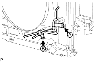
Temporarily install the oil cooler tube to the fan shroud with the bolt labeled A. Install the bolt labeled B. Then tighten the bolt labeled A to the specified torque.
5.0 N*m 51 kgf*cm 44 in.*lbf -
Connect the inlet No. 4 oil cooler hose as shown in the illustration.
Table 17. Text in Illustration *1 Paint Mark Note:Make sure the pinching portion of each clip is facing the direction shown in the illustration.
-
Connect the inlet No. 2 and No. 3 oil cooler hoses as shown in the illustration.
Note:Make sure the pinching portion of each clip is facing the direction shown in the illustration.
-
Connect the inlet and outlet No. 1 oil cooler hoses as shown in the illustration.
Table 18. Text in Illustration *1 Paint Mark Note:Make sure the pinching portion of each clip is facing the direction shown in the illustration.
-
Pass the hose through the flexible hose clamp and close the clamp shown in the illustration.
-
- Click here
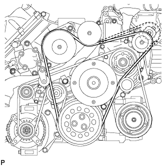
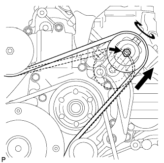
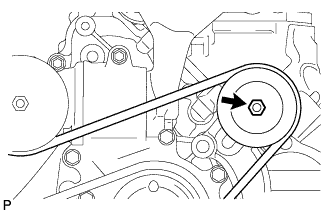
INSTALL V-RIBBED BELT
-
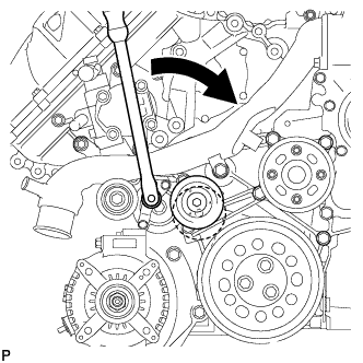
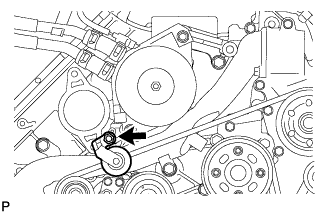
Attach a wrench to the V-ribbed belt tensioner bracket and turn the wrench clockwise.
-
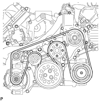
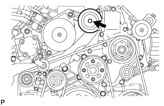
Install the V-ribbed belt as shown in the illustration.
-
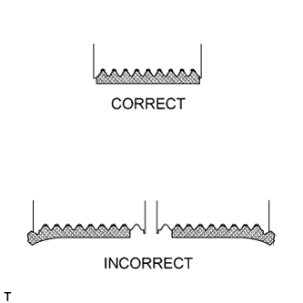
Check that the belt fits properly in the ribbed grooves.
Tip:Check with your hand to confirm that the belt has not slipped out of the groove on the bottom of the pulley.
If it has slipped out, replace the V-ribbed belt. Install a new V-ribbed belt.
-
- Click here
INSTALL NO. 3 IDLER PULLEY (w/ Viscous Heater)
-
Align the No. 3 idler pulley bracket knock pin and No. 1 idler pulley bracket knock pin hole and install the No. 3 idler pulley with the nut.
88 N*m 898 kgf*cm 64 ft.*lbf
-
- Click here
INSTALL NO. 1 IDLER PULLEY (w/ Viscous Heater)
-
Install the collar, No. 1 idler pulley and cover with the bolt.
49 N*m 495 kgf*cm 36 ft.*lbf
-
- Click here
INSTALL V-RIBBED BELT (w/ Viscous Heater)
-
Install the V-ribbed belt as shown in the illustration.
-
Temporarily install the lock nut, and turn the bolt clockwise.
-
Using a belt tension gauge, inspect the belt tension.
Standard Belt Tension Item Condition Specified Condition New belt 5 to 35°C (41 to 95°F) 550 to 800 N (56 to 82 kgf, 123.6 to 179.8 lbf) Used belt 5 to 35°C (41 to 95°F) 300 to 500 N (31 to 51 kgf, 67.4 to 112.4 lbf) Table 19. Text in Illustration *a Measuring Point Tip:
-
When measuring the tension of a new belt, measure the tension immediately after installing it to the engine but before starting the engine.
-
A "new belt" is a belt which has been used for less than 5 minutes on a running engine.
-
A "used belt" is a belt which has been used on a running engine for 5 minutes or more.
-
After installing a new belt, run the engine for approximately 5 minutes and then recheck the tension.
-
-
Tighten the nut.
40 N*m 408 kgf*cm 30 ft.*lbf -
Check that the belt fits properly in the ribbed grooves.
Tip:Check with your hand to confirm that the belt has not slipped out of the groove on the bottom of the pulley.
If it has slipped out, replace the V-ribbed belt. Install a new V-ribbed belt.
-
- Click here
CONNECT NO. 2 RADIATOR HOSE
- Click here
CONNECT NO. 1 RADIATOR HOSE
- Click here
INSTALL VANE PUMP ASSEMBLY
-
w/ DPF: (Click here)
-
w/o DPF: (Click here)
-
- Click here
INSTALL RADIATOR RESERVOIR ASSEMBLY
-
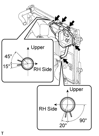
Install the radiator reservoir with the 3 bolts.
-
Connect the 2 hoses to the upper radiator tank and water inlet.
Tip:Make sure the directions of the hose clamps are as shown in the illustration.
-
- Click here
INSTALL NO. 1 OIL RESERVOIR BRACKET
-
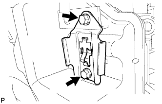
Install a new bracket with the 2 bolts.
4.5 N*m 46 kgf*cm 40 in.*lbf
-
- Click here
INSTALL VANE PUMP OIL RESERVOIR ASSEMBLY
-
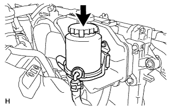
Install the vane pump oil reservoir to the bracket.
-
- Click here
INSTALL AIR CLEANER CASE
-
Install the air cleaner case with the 3 bolts.
5.0 N*m 51 kgf*cm 44 in.*lbf -
Attach the wire harness clamp to the air cleaner case.
-
- Click here
INSTALL AIR CLEANER FILTER ELEMENT
- Click here
INSTALL INTAKE AIR CONNECTOR
-
Connect the intake air connector to the No. 1 and No. 2 air cleaner pipes.
-
Install the connector with the 2 bolts.
21 N*m 214 kgf*cm 15 ft.*lbf -
Tighten the 2 hose clamps.
6.3 N*m 64 kgf*cm 56 in.*lbf -
Attach the 3 wire harness clamps.
-
w/o Viscous Heater:
Connect the connector to the water temperature sensor.
-
w/ Viscous Heater:
Connect the 2 connectors to the water temperature sensor and viscous with magnet clutch heater.
-
- Click here
TEMPORARILY INSTALL NO. 1 AIR CLEANER HOSE
-
Temporarily install the air cleaner hose to the intake air connector.
-
- Click here
INSTALL AIR CLEANER CAP SUB-ASSEMBLY
-
Connect the air cleaner cap to the air cleaner hose, and install the air cleaner cap with the 4 clamps.
-
Connect the mass air flow meter connector and attach the wire harness clamp to the air cleaner cap.
-
Attach the wire harness clamp.
-
Align the protrusion of the air cleaner cap and the concave portion of the air cleaner hose.
-
Tighten the 2 hose clamps.
2.5 N*m 25 kgf*cm 22 in.*lbf
-
- Click here
INSTALL INTERCOOLER ASSEMBLY (w/ Intercooler)
- Click here
INSTALL SUB-BATTERY
- Click here
INSTALL MAIN BATTERY
- Click here
INSTALL NO. 3 ENGINE ROOM WIRE
-
Install the No. 3 engine room wire to the main battery and sub-battery positive terminals with the 2 nuts.
7.6 N*m 77 kgf*cm 67 in.*lbf -
Connect the No. 3 engine room wire with the 4 clamps.
-
- Click here
INSTALL FRONT WHEEL
-
Click here
BLEED CLUTCH LINE
-
Remove the release cylinder bleeder plug cap.
-
Connect a vinyl tube to the bleeder plug.
-
Depress the clutch pedal several times, and then loosen the bleeder plug while the pedal is depressed.
-
When fluid no longer comes out, tighten the bleeder plug, and then release the clutch pedal.
-
Repeat the previous 2 steps until all the air in the fluid is completely bled.
-
Tighten the bleeder plug.
11 N*m 110 kgf*cm 8 ft.*lbf -
Install the bleeder plug cap.
-
Check that all the air has been bled from the clutch line.
-
- Click here
CHECK FOR CLUTCH FLUID LEAK
- Click here
CONNECT CABLE TO NEGATIVE BATTERY TERMINAL
Note:When disconnecting the cable, some systems need to be initialized after the cable is reconnected (Click here).
-
Connect the cables to the negative (-) main battery and sub-battery terminals.
-
- Click here
BLEED AIR FROM FUEL SYSTEM
-

Using the hand pump mounted on the fuel filter cap, bleed air from the fuel system. Continue pumping until the pump resistance increases.
Note:
-
The maximum hand pump pumping speed is 2 strokes per second.
-
The hand pump must be pushed with a full stroke during pumping.
-
When the fuel pressure at the supply pump inlet port reaches a saturated pressure, the hand pump resistance increases.
-
If pumping is interrupted during the air bleeding process, fuel in the fuel line may return to the fuel tank. Continue pumping until the hand pump resistance increases.
-
If the hand pump resistance does not increase despite consecutively pumping 200 times or more, there may be a fuel leak between the fuel tank and fuel filter, the hand pump may be malfunctioning, or the vehicle may have run out of fuel.
-
If air bleeding using the hand pump is incomplete, the common rail pressure does not rise to the pressure range necessary for normal use and the engine cannot be started.
-
-
Check if the engine starts.
Note:
-
Even if air bleeding using the hand pump has been completed, the starter may need to be cranked for 10 seconds or more to start the engine.
-
Do not crank the engine continuously for more than 20 seconds. The battery may be discharged.
-
Use a fully-charged battery.
-
When the engine can be started, proceed to the next step.
-
If the engine cannot be started, bleed air again using the hand pump until the hand pump resistance increases (refer to the procedures above). Then start the engine.
-
-
Turn the engine switch off.
-
Connect the intelligent tester to the DLC3.
-
Turn the ignition switch ON (IG) and turn the intelligent tester on.
-
Clear the DTCs (Click here).
-
Start the engine.*1
-
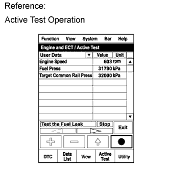
Enter the following menus: Powertrain / Engine and ECT / Active Test / Test the Fuel Leak.*2
-
Perform the following test 5 times with on/off intervals of 10 seconds: Active Test / Test the Fuel Leak.*3
-
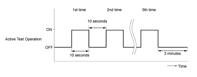
Allow the engine to idle for 3 minutes or more after performing the Active Test for the 5th time.
Tip:When the Active Test "Test the Fuel Leak" is used to change the pump control mode, the actual fuel pressure inside the common rail drops below the target fuel pressure when the Active Test is off, but this is normal and does not indicate a pump malfunction.
-
Enter the following menus: Powertrain / Engine and ECT / DTC.
-
Read Current DTCs.
-
Clear the DTCs (Click here).
Tip:It is necessary to clear the DTCs as DTC P1604 or P1605 may be stored when air is bled from the fuel system after replacing or repairing fuel system parts.
-
Repeat steps *1 to *3.
-
Enter the following menus: Powertrain / Engine and ECT / DTC.
-
Read Current DTCs.
OK No DTCs are output.
-
- Click here
ADD ENGINE COOLANT
-
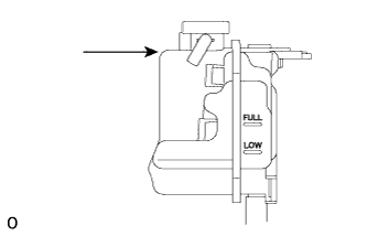
Remove the engine air bleed cap.
-
Connect a clear hose to the engine air bleed pipe.
-
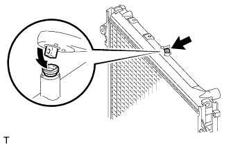
Using a wrench, remove the vent plug.
-
Fill the radiator with TOYOTA SLLC to the radiator reservoir filler neck.
Tip:Pour TOYOTA SLLC until it spills out of the engine air bleed pipe.
Standard Capacity (for Automatic Transmission) Item Specified Condition Front heater only 14.8 liters (15.6 US qts, 13.0 Imp. qts) Front heater and rear heater 17.6 liters (18.6 US qts, 15.5 Imp. qts) Front heater with viscous heater 15.2 liters (16.1 US qts, 13.4 Imp. qts) Front heater and rear heater with viscous heater 18.0 liters (19.0 US qts, 15.4 Imp. qts) Standard capacity (for Manual Transmission) 15.4 liters (16.3 US qts, 13.5 Imp. qts) Note:Do not substitute plain water for engine coolant.
Tip:TOYOTA vehicles are filled with TOYOTA SLLC at the factory. In order to avoid damage to the engine cooling system and other technical problems, only use TOYOTA SLLC or similar high quality ethylene glycol based non-silicate, non-amine, non-nitrite, non-borate coolant with long-life hybrid organic acid technology (coolant with long-life hybrid organic acid technology consists of a combination of low phosphates and organic acids).
-
Install the vent plug.
2.0 N*m 20 kgf*cm 18 in.*lbf Note:Do not tighten the plug to 5.0 N*m (51 kgf*cm, 44 in.*lbf) or more, as the plug will be damaged.
-
Disconnect the clear hose from the engine air bleed pipe.
-
Install the engine air bleed cap when coolant comes out.
-
Install the radiator reservoir cap.
-
Start the engine.
Note:Immediately after starting the engine, if the radiator reservoir does not have any coolant, perform the following: 1) stop the engine, 2) wait until the coolant has cooled down, and 3) add coolant until the coolant is filled to the FULL line.
-
Maintain an engine speed of 3000 rpm for approximately 10 minutes so that the thermostat opens and air bleeding is performed.
CAUTION:
- When pressing the radiator hoses:
-
Wear protective gloves.
-
Be careful as the radiator hoses are hot.
-
Keep your hands away from the radiator fan
Note:
-
Pay attention to the needle of the water temperature meter. Make sure that the needle does not show an abnormally high temperature.
-
If there is not enough coolant, the engine may burn out or overheat.
Tip:The thermostat opening timing can be confirmed by pressing the No. 2 radiator hose by hand, and checking when the engine coolant starts to flow inside the hose.
-
Stop the engine, and wait until the engine coolant cools down to ambient temperature.
CAUTION:Do not remove the radiator reservoir cap while the engine and radiator are still hot. Pressurized, hot engine coolant and steam may be released and cause serious burns.
-
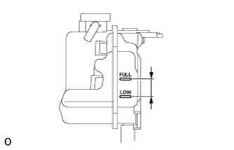
Check that the coolant level is between the FULL and LOW lines.
If the coolant level is above the FULL line, drain coolant so that the coolant level is between the FULL and LOW lines.
-
- Click here
INSPECT FOR FUEL LEAK
-
Perform Active Test.
-
Connect the intelligent tester to the DLC3.
-
Turn the ignition switch to ON.
-
Start the engine.
-
Turn the intelligent tester ON.
-
Enter the following menus: Powertrain / Engine and ECT / Active Test.
-
Perform the Active Test.
Tester Display Test Detail Control Range Diagnostic Note Test the Fuel Leak Pressurizes fuel inside common rail and checks for fuel leaks Stop/Start
-
The fuel inside the common rail is pressurized to the specified value and the engine speed increases to 2000 rpm when Start is selected.
-
The above conditions are preserved while Start is selected.
-
-
-
- Click here
INSPECT FOR OIL LEAK
-
Perform Active Test.
-
Connect the intelligent tester to the DLC3.
-
Turn the ignition switch to ON.
-
Start the engine.
-
Turn the intelligent tester ON.
-
Enter the following menus: Powertrain / Engine and ECT / Active Test.
-
Perform the Active Test.
Tester Display Test Detail Control Range Diagnostic Note Test the Fuel Leak Pressurizes fuel inside common rail and checks for fuel leaks Stop/Start
-
The fuel inside the common rail is pressurized to the specified value and the engine speed increases to 2000 rpm when Start is selected.
-
The above conditions are preserved while Start is selected.
-
-
-
- Click here
INSPECT FOR COOLANT LEAK
CAUTION:Do not remove the radiator reservoir cap while the engine and radiator are still hot. Pressurized, hot engine coolant and steam may be released and cause serious burns.
-
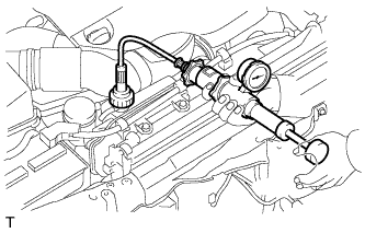
Fill the radiator with coolant and attach a radiator cap tester to the radiator reservoir.
-
Warm up the engine.
-
Using the radiator cap tester, increase the pressure inside the radiator to 123 kPa (1.3 kgf/cm2, 17.8 psi), and check that the pressure does not drop.
If the pressure drops, check the hoses, radiator and water pump for leaks.
If no external leaks are found, check the cylinder block and cylinder head.
-
- Click here
INSPECT FOR EXHAUST GAS LEAK
- Click here
CHARGE REFRIGERANT
09985-20010 09985-02130 09985-02150 09985-02090 09985-02110 09985-02010 09985-02050 09985-02060 09985-02070
-
Perform vacuum purging using a vacuum pump.
-

Charge refrigerant HFC-134a (R134a).
Table 20. Standard: Condenser Core Thickness Air Conditioning Type Cool Box Refrigerant Charging Amount 22 mm (0.866 in.) w/o Rear Cooler w/ Cool Box 870 +/-30 g (30.7 +/-1.1 oz.) w/o Cool Box 870 +/-30 g (30.7 +/-1.1 oz.) w/ Rear Cooler w/ Cool Box 1010 +/-30 g (35.6 +/-1.1 oz.) w/o Cool Box 960 +/-30 g (33.9 +/-1.1 oz.) 16 mm (0.630 in.) w/o Rear Cooler w/ Cool Box 770 +/-30 g (27.2 +/-1.1 oz.) w/o Cool Box 770 +/-30 g (27.2 +/-1.1 oz.) w/ Rear Cooler w/ Cool Box 970 +/-30 g (34.2 +/-1.1 oz.) w/o Cool Box 920 +/-30 g (32.5 +/-1.1 oz.) Note:
-
Do not operate the cooler compressor before charging refrigerant as the cooler compressor will not work properly without any refrigerant, and will overheat.
-
Approximately 200 g (7.05 oz.) of refrigerant may need to be charged after bubbles disappear. The refrigerant amount should be checked by measuring its quantity, and not with the sight glass.
-
-
- Click here
WARM UP ENGINE
-
Warm up the engine at less than 1850 rpm for 2 minutes or more after charging the refrigerant.
Note:Be sure to warm up the compressor when turning the A/C switch is on after removing and installing the cooler refrigerant lines (including the compressor), to prevent damage to the compressor.
-
- Click here
CHECK FOR REFRIGERANT GAS LEAK
-
After recharging the refrigerant gas, check for refrigerant gas leakage using a halogen leak detector.
-
Perform the operation under these conditions:
-
Stop the engine.
-
Secure good ventilation (the halogen leak detector may react to volatile gases other than refrigerant, such as evaporated gasoline or exhaust gas).
-
Repeat the test 2 or 3 times.
-
Make sure that some refrigerant remains in the refrigeration system. When compressor is off: approximately 392 to 588 kPa (4.0 to 6.0 kgf/cm2, 57 to 85 psi).
-
-
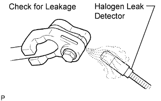
Using a halogen leak detector, check the refrigerant line for leakage.
-
If a gas leak is not detected on the drain hose, remove the blower motor control (blower resistor) from the cooling unit. Insert the halogen leak detector sensor into the unit and perform the test.
-
Disconnect the connector and wait for approximately 20 minutes. Bring the halogen leak detector close to the pressure switch and perform the test.
-
- Click here
INSTALL FRONT FENDER APRON SEAL REAR LH
-
Install the front fender apron seal rear LH with the 4 clips.
-
- Click here
INSTALL FRONT FENDER APRON SEAL FRONT LH
-
w/o KDSS:
Install the front fender apron seal front LH with the 4 clips.
-
w/ KDSS:
Install the front fender apron seal front LH with the 3 clips.
-
- Click here
INSTALL FRONT FENDER APRON SEAL REAR RH
-
Install the front fender apron seal rear RH with the 4 clips.
-
- Click here
INSTALL FRONT FENDER APRON SEAL FRONT RH
-
Install the front fender apron seal front RH with the 3 clips.
-
-
Click here
INSTALL OIL PAN PROTECTOR ASSEMBLY
-
Install the oil pan protector with the 4 bolts.
63 N*m 642 kgf*cm 46 ft.*lbf
-
- Click here
INSTALL NO. 2 ENGINE UNDER COVER
-
Install the No. 2 engine under cover with the 2 bolts.
29 N*m 296 kgf*cm 21 ft.*lbf
-
- Click here
INSTALL NO. 1 ENGINE UNDER COVER SUB-ASSEMBLY
-
Install the No. 1 engine under cover with the 10 bolts.
29 N*m 296 kgf*cm 21 ft.*lbf
-
- Click here
INSTALL FRONT FENDER SPLASH SHIELD SUB-ASSEMBLY RH
-
Install the front fender splash shield RH with the clip, and then install the 3 bolts and 2 screws.
-
- Click here
INSTALL FRONT FENDER SPLASH SHIELD SUB-ASSEMBLY LH
-
Install the front fender splash shield LH with the clip, and then install the 3 bolts and screw.
-
- Click here
INSTALL COWL TOP VENTILATOR LOUVER SUB-ASSEMBLY
- Click here
INSTALL HOOD SUB-ASSEMBLY
-
Install the hood with the 4 bolts.
13 N*m 133 kgf*cm 10 ft.*lbf -
Install the 2 hood supports with the 2 bolts.
18 N*m 184 kgf*cm 13 ft.*lbf Note:
-
As much as possible avoid touching the stroke portions of the rod to prevent foreign matter from attaching to it. Be sure to hold the cylinders while servicing.
-
Do not wear cotton gloves or other similar materials when handling the rod. Fibers may attach to the rod and result in gas leaks.
-
Do not apply any load to the cylinders in the horizontal direction in order to prevent the rod from being deformed.
-
Install the hood support while supporting the hood by hand.
-
-
- Click here
ADJUST HOOD SUB-ASSEMBLY
- Click here
INSPECT ENGINE OIL LEVEL
-
Warm up the engine, stop the engine and wait 5 minutes. The engine oil level should be between the dipstick low level mark and full level mark.
If low, check for leakage and add oil up to the full level mark.
Note:Do not fill engine oil above the full level mark.
Tip:A certain amount of engine oil will be consumed while driving. In the following situations, oil consumption may increase, and engine oil may need to be refilled in between oil maintenance intervals.
-
When the engine is new, for example directly after purchasing the vehicle or after replacing the engine.
-
If low quality oil or oil of an inappropriate viscosity is used.
-
When driving at high engine speed or with a heavy load, (when towing, or), when driving while accelerating or decelerating frequently.
-
When leaving the idling for a long time, or when driving frequently through heavy traffic.
When judging the amount of oil consumption, keep in mind that the oil may have become diluted, making it difficult to judge the true level accurately.
-
-
-
Click here
INSPECT ENGINE COOLANT LEVEL IN RESERVOIR
-
Check that the engine coolant level is between the LOW and FULL lines when the engine is cold.
If the engine coolant is low, check for leaks and add "TOYOTA Super Long Life Coolant (SLLC)" or similar high quality ethylene glycol based non-silicate, non-amine, non-nitrite and non-borate coolant with long-life hybrid organic acid technology to the FULL line.
Note:Do not substitute plain water for engine coolant.
-
- Click here
INSPECT ENGINE IDLE SPEED
Note:
-
Turn all the electrical systems and the A/C off.
-
When checking the idle speed, move the shift lever to neutral.
Tip:
-
For more information about the GTS, refer to its operator's manual.
-
If an GTS is not available, use a tachometer tester probe as a substitute.
-
When using the GTS:
-
Warm up the engine.
-
Connect the GTS to the DLC3.
-
Enter the following menus:
Powertrain / Engine / Data List / Engine Speed.
Tip:Refer to the GTS operator's manual for help selecting the Data List.
-
Inspect the engine idle speed.
Standard Idle Speed Item Specified Condition for Automatic Transmission 550 to 750 rpm for Manual Transmission 500 to 600 rpm -
Disconnect the GTS from the DLC3.
-
-
When not using the GTS:
-
Warm up and stop the engine.
-
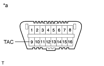
Connect a tester probe of a tachometer to terminal 9 (TAC) of the DLC3 with SST.
09843-18040 Table 21. Text in Illustration *a Front view of DLC3 -
Inspect the engine idle speed.
Standard Idle Speed Item Specified Condition for Automatic Transmission 550 to 750 rpm for Manual Transmission 500 to 600 rpm -
Disconnect the tester probe from terminal 9 (TAC) of the DLC3.
-
-
- Click here
INSPECT MAXIMUM ENGINE SPEED
-
Start the engine.
-
Fully depress the accelerator pedal.
-
Check the maximum engine speed.
Maximum engine speed 4700 to 4900 rpm
-
- Click here
INSTALL UPPER RADIATOR SUPPORT SEAL
-
Install the upper radiator support seal with the 7 clips.
-
- Click here
INSTALL NO. 1 ENGINE COVER SUB-ASSEMBLY (w/ Intercooler)
-
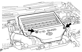
Install the engine cover with the 2 nuts.
8.0 N*m 82 kgf*cm 71 in.*lbf
-
- Click here
PERFORM CRANK TIME COMPENSATION RESET FUNCTION