ENGINE ASSEMBLY REMOVAL

-
DISCHARGE FUEL SYSTEM PRESSURE
CAUTION:
-
Do not disconnect any part of the fuel system until you have discharged the fuel system pressure.
-
After discharging the fuel pressure, place a cloth or equivalent over fittings as you separate them to reduce the risk of fuel spray on yourself or in the engine compartment.
-
Disconnect the fuel pump ECU connector Click here.
-
Start the engine. After the engine stops, turn the engine switch off.
Tech Tips
DTC P0171/0174 (system too lean) may be stored.
-
Crank the engine again, and then check that the engine does not start.
-
Loosen the fuel tank cap, and then discharge the pressure in the fuel tank completely.
-
Disconnect the cable from the negative (-) battery terminal.
Note
-
After turning the engine switch off, waiting time may be required before disconnecting the cable from the battery terminal. Therefore, make sure to read the disconnecting the cable from the battery terminal notice before proceeding with work Click here.
-
When disconnecting the cable, some systems need to be initialized after the cable is reconnected Click here.
-
-
Connect the fuel pump ECU connector Click here.
-
-
PRECAUTION
Note
After turning the engine switch off, waiting time may be required before disconnecting the cable from the battery terminal. Therefore, make sure to read the disconnecting the cable from the battery terminal notice before proceeding with work Click here.
-
DISCONNECT CABLE FROM NEGATIVE BATTERY TERMINAL
Note
When disconnecting the cable, some systems need to be initialized after the cable is reconnected Click here.
-
REMOVE FRONT BUMPER COVER
-
for Standard Click here
-
w/ Winch Click here
-
-
REMOVE TRANSMISSION OIL COOLER AIR DUCT (w/ Air Cooled Transmission Oil Cooler)
-
Remove the 4 bolts and oil cooler air duct.
-
-
REMOVE RADIATOR SIDE DEFLECTOR RH (w/o Air Cooled Transmission Oil Cooler)
-
Using a clip remover, remove the 4 clips and move the side deflector so that the radiator can be removed in a later step.
-
-
REMOVE RADIATOR SIDE DEFLECTOR LH
-
Using a clip remover, remove the 4 clips and move the side deflector so that the radiator can be removed in a later step.
-
-
REMOVE HOOD SUB-ASSEMBLY
-
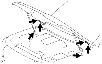
Remove the 2 hood support bolts and disconnect the hood supports.
CAUTION:
Remove the hood support assembly while supporting the hood by hand.
-
Remove the 4 bolts and hood.
-
-
REMOVE COWL TOP VENTILATOR LOUVER SUB-ASSEMBLY
-
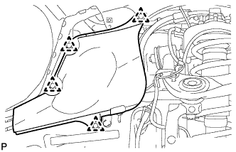
REMOVE FRONT FENDER APRON TRIM PACKING B
-
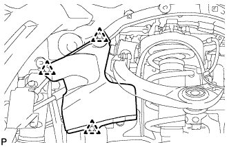
w/ KDSS:
Remove the 3 clips and front fender apron trim packing B.
-
w/o KDSS:
Remove the 4 clips and front fender apron trim packing B.
-
-
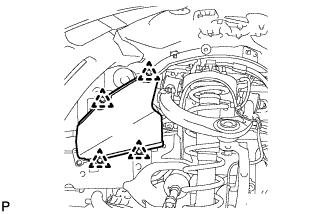
REMOVE FRONT FENDER APRON TRIM PACKING D
-
Remove the 4 clips and front fender apron trim packing D.
-
-
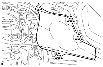
REMOVE FRONT FENDER APRON TRIM PACKING A
-
Remove the 3 clips and front fender apron trim packing A.
-
-
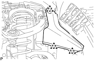
REMOVE FRONT FENDER APRON TRIM PACKING C
-
Remove the 4 clips and front fender apron trim packing C.
-
-
REMOVE NO. 1 ENGINE UNDER COVER SUB-ASSEMBLY
-
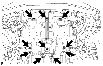
Remove the 10 bolts and No. 1 engine under cover sub-assembly.
-
-
REMOVE NO. 2 ENGINE UNDER COVER
-
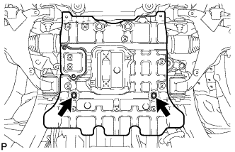
Remove the 2 bolts and No. 2 engine under cover.
-
-
REMOVE OIL PAN PROTECTOR ASSEMBLY
-
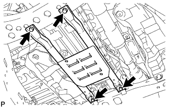
Remove the 4 bolts and oil pan protector assembly.
-
-
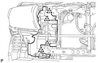
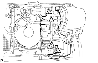
REMOVE V-BANK COVER SUB-ASSEMBLY
-
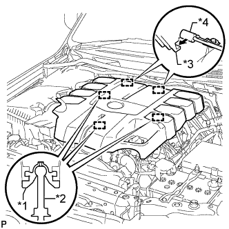
Text in Illustration *1 Grommet *2 Pin *3 Hook *4 Bracket Raise the front of the V-bank cover to detach the 3 pins. Then remove the 2 V-bank cover hooks from the bracket, and remove the V-bank cover.
-
-
DRAIN ENGINE OIL
-
Remove the oil filler cap.
-
Remove the 2 bolts and No. 2 engine under cover seal.
-
Remove the oil pan drain plug and gasket, and drain the engine oil into a container.
-
Install a new gasket and the oil pan drain plug.
- Torque:
- 40 N*m { 408 kgf*cm, 30 ft.*lbf }
-
Install the No. 2 engine under cover seal with the 2 bolts.
- Torque:
- 10 N*m { 102 kgf*cm, 7 ft.*lbf }
-
-
DRAIN ENGINE COOLANT
CAUTION:
Do not remove the radiator cap while the engine and radiator are still hot. Pressurized, hot engine coolant and steam may be released and cause serious burns.
-
Loosen the radiator drain cock plug.
-
Remove the radiator cap and drain the coolant.
Tech Tips
Collect the coolant in a container and dispose of it according to the regulations in your area.
-
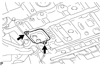
Loosen the 2 cylinder block drain cock plugs and drain the coolant from the engine.
-
Tighten the 2 cylinder block drain cock plugs.
- Torque:
- 13 N*m { 130 kgf*cm, 9 ft.*lbf }
-
Tighten the radiator drain cock plug by hand.
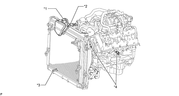
Text in Illustration *1 Reservoir Cap *2 Radiator Cap *3 Radiator Drain Cock Plug *4 Cylinder Block Drain Cock Plug
-
-
DRAIN AUTOMATIC TRANSMISSION FLUID
-
Remove the drain plug and gasket, and drain the ATF.
-
Install a new gasket and the drain plug.
- Torque:
- 20 N*m { 204 kgf*cm, 15 ft.*lbf }
-
-
REMOVE BATTERY
-
Remove the bolt and loosen the nut.
-
Detach the hook of the battery clamp from the battery bracket, and then remove the battery clamp.
-
Remove the battery.
-
-
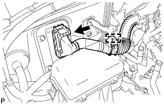
REMOVE AIR CLEANER AND HOSE
-
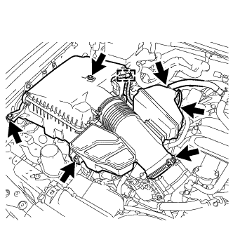
Disconnect the No. 2 PCV hose and No. 1 air hose.
-
Disconnect the mass air flow meter connector and detach the clamp.
-
Remove the 3 bolts and loosen the hose clamp, and then remove the air cleaner and hose.
-
-
REMOVE NO. 1 RADIATOR HOSE
-
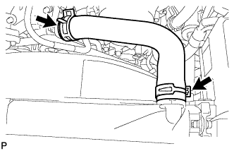
Remove the No. 1 radiator hose.
-
-
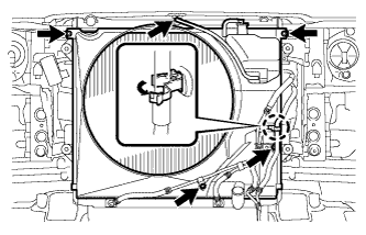
REMOVE FAN SHROUD
-
Loosen the 4 nuts holding the fluid coupling fan.
-
Remove the fan and generator V-belt Click here.
-
Disconnect the reservoir hose from the upper radiator tank.
-
w/ Air Cooled Transmission Oil Cooler:
Detach the claw to open the flexible hose clamp.
-
Remove the 2 bolts and disconnect the oil cooler tube from the fan shroud.
-
Remove the 2 bolts holding the fan shroud.
-
Remove the 4 nuts of the fluid coupling fan, and then remove the shroud together with the fluid coupling fan.
Note
Be careful not to damage the radiator core.
-
Remove the fan pulley from the engine water pump.
-
-
REMOVE NO. 2 RADIATOR HOSE
-
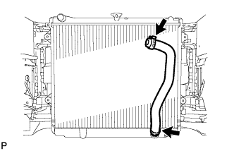
Remove the No. 2 radiator hose.
-
-
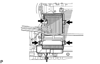
REMOVE RADIATOR ASSEMBLY
-
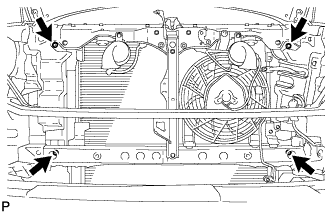
Remove the 4 bolts and radiator.
-
-
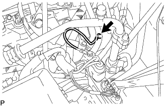
DISCONNECT NO. 3 AIR INJECTION SYSTEM HOSE (w/ Secondary Air Injection System)
-
Disconnect the No. 3 air injection system hose from the air tube sub-assembly.
-
-
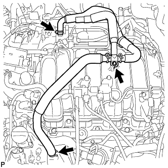
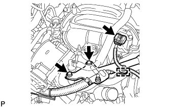
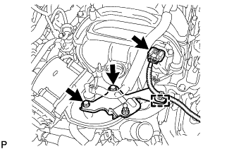
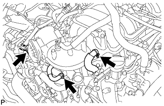
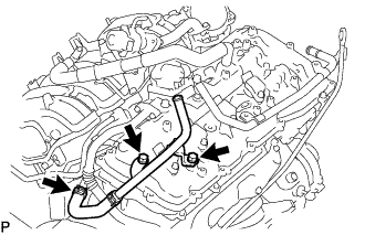
REMOVE NO. 5 WATER BY-PASS PIPE
-
Disconnect the 2 water by-pass hoses and remove the 2 bolts and No. 5 water by-pass pipe.
-
-
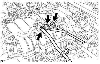
REMOVE EGR VALVE BRACKET
-
Detach the 2 wire harness clamps and PCV hose clamp.
-
Remove the 3 bolts and EGR valve bracket.
-
-
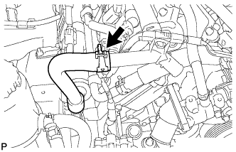
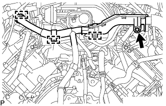
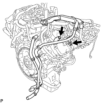
REMOVE PCV HOSE ASSEMBLY
-
Disconnect the PCV hose from the PCV pipe of the cylinder head cover LH and RH.
-
Remove the bolt and PCV hose.
-
-
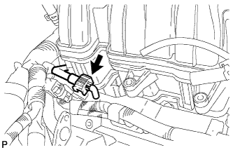
REMOVE AIR TUBE SUB-ASSEMBLY (w/ Secondary Air Injection System)
-
Disconnect the No. 2 air injection system hose from the air switching valve.
-
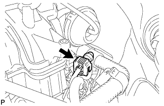
Disconnect the manifold absolute pressure sensor connector and detach the clamp.
-
Remove the 2 bolts and bracket.
-
Remove the bolt and air tube.
-
-
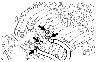
REMOVE INTAKE MANIFOLD
-
w/o Secondary Air Injection System:
-
Disconnect the manifold absolute pressure sensor connector and detach the clamp.
-
Remove the 2 bolts and bracket.
-
-
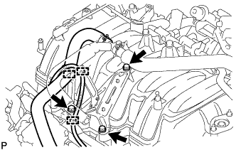
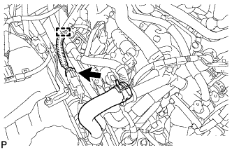
Disconnect the No. 4 water by-pass hose.
-
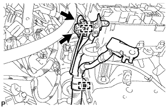
Disconnect the throttle position sensor and throttle control motor connector.
-
Disconnect the PCV valve hose.
-
Disconnect the purge VSV connector.
-
Disconnect the purge line hose from the purge VSV.
-
Disconnect the vacuum switching valve connector (for ACIS).
-
Remove the bolt.
-
Detach the 3 wire harness clamps from the 3 wire harness brackets.
-
Disconnect the fuel tube from the fuel delivery pipe Click here.
-
Disconnect the fuel tube from the No. 2 fuel delivery pipe Click here.
-
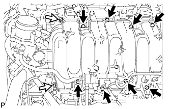
Remove the 2 nuts, 8 bolts, intake manifold and 2 gaskets.
Text in Illustration 
Bolt 
Nut
-
-
REMOVE ENGINE OIL LEVEL DIPSTICK GUIDE
-
Remove the engine oil level dipstick.
-
Detach the engine wire clamp.
-
Remove the bolt and engine oil level dipstick guide.
-
Remove the O-ring from the engine oil level dipstick guide.
-
-
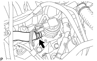
DISCONNECT SUCTION HOSE
-
Slide the clip and disconnect the suction hose from the vane pump.
-
-
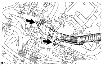
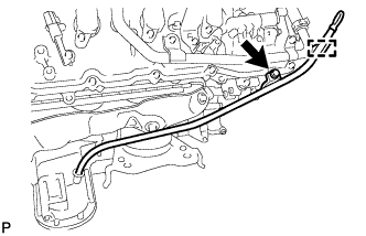
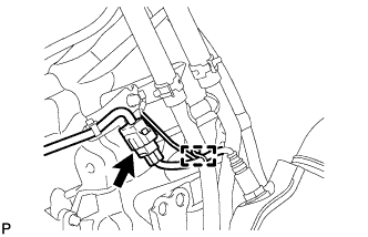
DISCONNECT PRESSURE FEED TUBE
-
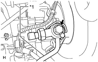
Text in Illustration *1 Pressure Feed Tube Remove the bolt and disconnect the pressure feed tube.
-
Remove the gasket.
-
-
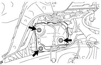
REMOVE VANE PUMP ASSEMBLY
-
Remove the 2 bolts and vane pump.
-
-
REMOVE GENERATOR ASSEMBLY
-
for 130A, 150A Type:
-
for 180A Type:
-
-
DISCONNECT COOLER COMPRESSOR ASSEMBLY
-
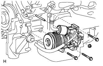
Remove the 3 bolts, nut and stud bolt, and then disconnect the cooler compressor.
Tech Tips
It is not necessary to completely remove the compressor. With the hoses connected to the compressor, hang the compressor on the vehicle body with a rope.
-
-
REMOVE PROPELLER SHAFT HEAT INSULATOR
-
Remove the 2 bolts and insulator.
-
-
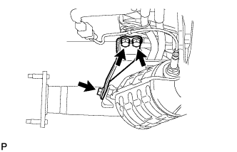
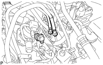
DISCONNECT HEATED OXYGEN SENSOR (for Bank 1 Sensor 2)
-
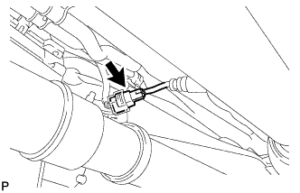
Disconnect the heated oxygen sensor connector.
-
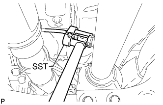
Using SST, remove the heated oxygen sensor from the front No. 2 exhaust pipe.
- SST
- 09224-00010
-
-
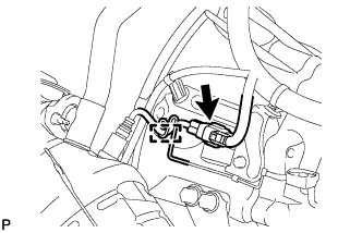
DISCONNECT HEATED OXYGEN SENSOR (for Bank 2 Sensor 2)
-
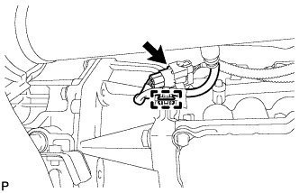
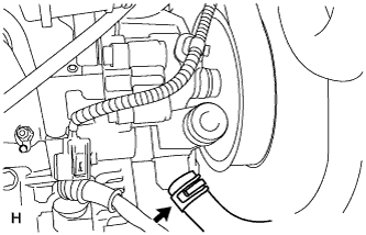
Detach the clamp and disconnect the heated oxygen sensor connector.
-
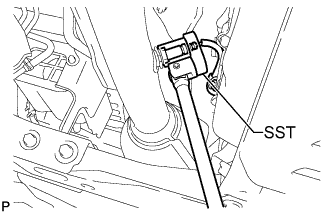
Using SST, remove the heated oxygen sensor from the front exhaust pipe.
- SST
- 09224-00010
-
-
REMOVE TAILPIPE ASSEMBLY
-
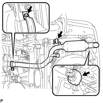
Remove the bolt and exhaust tailpipe clamp.
-
Remove the 2 exhaust pipe supports, gasket and tailpipe.
-
-
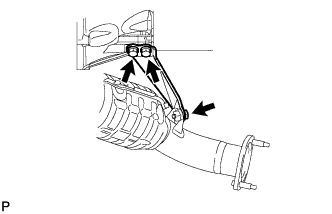
REMOVE CENTER EXHAUST PIPE ASSEMBLY
-
Remove the 4 bolts and disconnect the center exhaust pipe.
-
Remove the 3 exhaust pipe supports, 2 gaskets and center exhaust pipe.
-
-
REMOVE FRONT NO. 2 EXHAUST PIPE ASSEMBLY
-
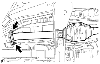
Remove the 2 nuts and front No. 2 exhaust pipe.
-
Remove the gasket.
-
-
REMOVE FRONT EXHAUST PIPE ASSEMBLY
-
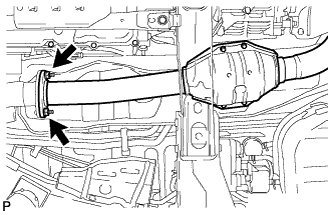
Remove the 2 nuts and front exhaust pipe.
-
Remove the gasket.
-
-
REMOVE NO. 2 MANIFOLD STAY
-
Remove the 3 bolts and No. 2 manifold stay.
-
-
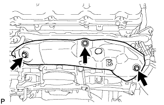
REMOVE MANIFOLD STAY
-
Remove the 3 bolts and manifold stay.
-
-
REMOVE NO. 2 EXHAUST MANIFOLD HEAT INSULATOR
-
Remove the 3 bolts and No. 2 exhaust manifold heat insulator.
-
-
REMOVE EXHAUST MANIFOLD ASSEMBLY LH
-
Disconnect the air fuel ratio sensor connector and detach the wire harness clamp.
-
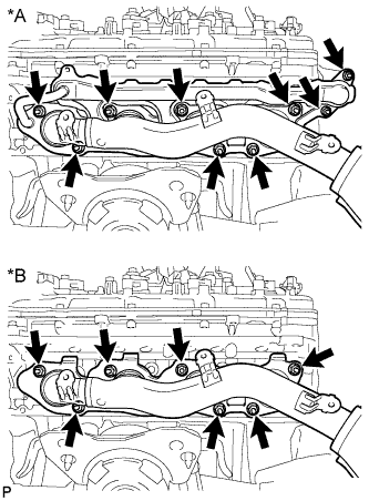
Text in Illustration *A w/ Secondary Air Injection System *B w/o Secondary Air Injection System w/ Secondary Air Injection System:
Remove the 9 nuts, exhaust manifold and 2 gaskets.
-
w/o Secondary Air Injection System:
Remove the 7 nuts, exhaust manifold and gasket.
-
-
REMOVE NO. 1 EXHAUST MANIFOLD HEAT INSULATOR
-
Remove the 3 bolts and heat insulator.
-
-
REMOVE EXHAUST MANIFOLD ASSEMBLY RH
-
Disconnect the air fuel ratio sensor connector and detach the wire harness clamp.
-
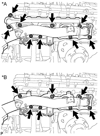
Text in Illustration *A w/ Secondary Air Injection System *B w/o Secondary Air Injection System w/ Secondary Air Injection System:
Remove the 9 nuts, exhaust manifold and 2 gaskets.
-
w/o Secondary Air Injection System:
Remove the 7 nuts, exhaust manifold and 2 gaskets.
-
-
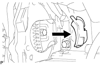
REMOVE STARTER COVER
-
Remove the 3 bolts and starter cover.
-
-
REMOVE STARTER ASSEMBLY
-
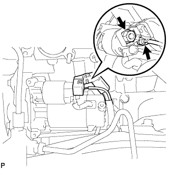
Disconnect the starter connector.
-
Remove the nut and disconnect the starter wire.
-
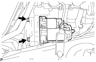
Remove the 2 bolts and starter.
-
Remove the flywheel housing side cover.
-
-
DISCONNECT FUEL HOSE AND FUEL TUBE SUB-ASSEMBLY
-
Remove the fuel pipe clamp from the fuel tube connector.
-
Disconnect the fuel hose and fuel tube sub-assembly Click here.
-
-
DISCONNECT ENGINE WIRE
-
Disconnect the clamp and ECM connector.
Tech Tips
Refer to the following procedures to disconnect the ECM connector Click here.
-
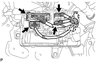
Disconnect the 4 connectors and 2 clamps from the connector holder block.
-
Remove the bolt and disconnect the ground wire.
-
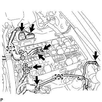
Remove the nut and disconnect the wire and 2 clips from the engine room junction block.
-
Disconnect the 2 connectors and 2 clips from the engine room junction block.
-
w/ Secondary Air Injection System:
Disconnect the 2 air injection control driver connectors.
-
Remove the bolt, disconnect the clamp and ground wire.
-
Remove the nut and disconnect the wire from the positive (+) battery cable.
-
Disconnect the 2 connectors and 2 clips from the engine room junction block.
-
w/ Secondary Air Injection System:
Disconnect the connector and clamp.
-
-
DISCONNECT TRANSMISSION OIL COOLER HOSE
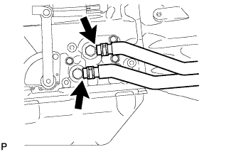
-
Disconnect the 2 transmission oil cooler hoses from the oil cooler tube unions.
-
-
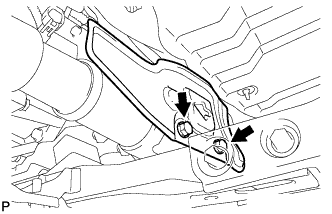
REMOVE OIL COOLER TUBE
-
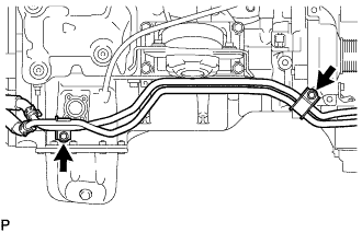
Remove the 2 bolts and disconnect the oil cooler tube.
-
-
REMOVE FRONT PROPELLER SHAFT ASSEMBLY
-
REMOVE PROPELLER SHAFT ASSEMBLY
-
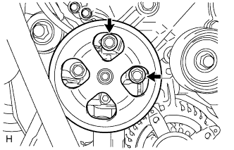
REMOVE DRIVE PLATE AND TORQUE CONVERTER SETTING BOLT
-
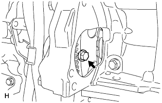
Turn the crankshaft to gain access to the 6 bolts and remove the bolts while holding the crankshaft pulley setting bolt with a wrench.
-
-
REMOVE AUTOMATIC TRANSMISSION ASSEMBLY
-
REMOVE NO. 1 WATER BY-PASS PIPE (w/ ATF Warmer)
-
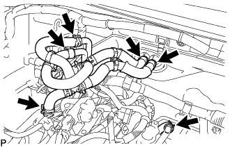
w/ Rear Heater:
Disconnect the 6 water hoses.
-
Remove the 2 bolts and No. 1 water by-pass pipe.
-
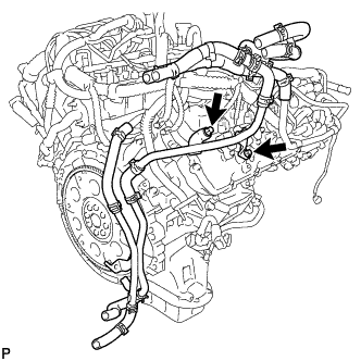
w/o Rear Heater:
Disconnect the 4 water hoses.
-
Remove the 2 bolts and No. 1 water by-pass pipe.
-
-
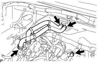
REMOVE NO. 1 WATER BY-PASS PIPE (w/o ATF Warmer)
-
Disconnect the hose.
-
Remove the 2 bolts and No. 1 water by-pass pipe.
-
-
REMOVE REAR NO. 1 ENGINE MOUNTING INSULATOR
-
Remove the 2 bolts and engine mounting heat insulator.
-
Remove the 4 bolts and rear engine No. 1 mounting insulator from the transmission.
-
-
REMOVE DRIVE PLATE AND RING GEAR SUB-ASSEMBLY
-
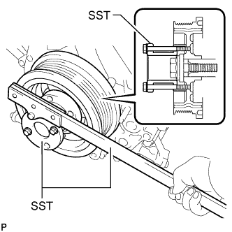
Using SST, hold the crankshaft.
- SST
- 09213-70011 ( 09213-70020 )
- 09330-00021
-
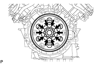
Remove the 10 bolts, the rear drive plate spacer, the drive plate and ring gear, and the crankshaft angle sensor rotor.
-
-
INSTALL ENGINE HANGER
-
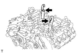
Install 2 engine hangers with 2 bolts as shown in the illustration.
- Torque:
- 43 N*m { 438 kgf*cm, 32 ft.*lbf }
Tech Tips
Engine Hanger 12281-38150 Bolt 90119-14120
-
-
REMOVE ENGINE ASSEMBLY
-
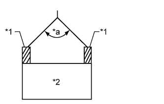
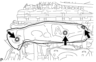
Text in Illustration *1 Engine Hanger *2 Engine *a 50° or less Attach an engine sling device and hang the engine with a chain block.
Note
When hanging the engine, make sure to hang the engine with the angle of the sling device at 50° or less. Otherwise, the engine or engine hangers may be damaged.
-
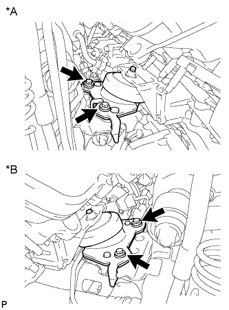
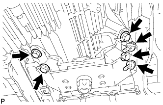
Text in Illustration *A for LH Side *B for RH Side Remove the 2 nuts and 4 bolts from the front engine mounting insulator LH and RH.
-
Lift the engine out of the vehicle carefully.
Note
-
Make sure the engine is clear of all wiring, hoses and cables.
-
With the exception of installing the engine assembly to an engine stand or removing the engine assembly from an engine stand, do not perform any work on the engine while it is suspended, as doing so is dangerous.
-
Pay attention to the angle of the sling device as the engine assembly or engine hangers may be damaged or deformed if the angle is incorrect.
-
-
Remove the front engine mounting insulator LH and RH.
-
Place the engine onto a workbench.
-
-
INSTALL ENGINE STAND
-
Install the engine to an engine stand with bolts.
-
Remove the 2 bolts and 2 engine hangers.
-
-
REMOVE FRONT ENGINE MOUNTING INSULATOR LH
-
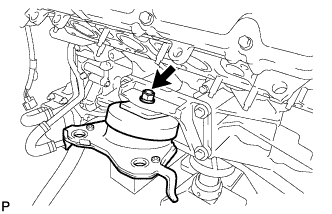
Remove the nut and mounting insulator.
-
-
REMOVE FRONT ENGINE MOUNTING INSULATOR RH
-
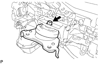
Remove the nut and mounting insulator.
-
-
REMOVE NO. 2 FRONT ENGINE MOUNTING BRACKET LH
-
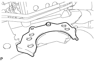
Remove the bolt and No. 2 front engine mounting bracket LH.
-