ENGINE ASSEMBLY REMOVAL

-
RECOVER REFRIGERANT FROM REFRIGERATION SYSTEM
-
Start the engine.
-
Turn the A/C switch on.
-
Operate the cooler compressor while the engine speed is approximately 1000 rpm for 5 to 6 minutes to circulate the refrigerant and collect the compressor oil remaining in each component into the cooler compressor.
-
Stop the engine.
-
Recover the refrigerant from the A/C system using a refrigerant recovery unit.
-
-
DISCHARGE FUEL SYSTEM PRESSURE
-
PRECAUTION
Note
After turning the ignition switch off, waiting time may be required before disconnecting the cable from the battery terminal. Therefore, make sure to read the disconnecting the cable from the battery terminal notice before proceeding with work Click here.
-
DISCONNECT CABLE FROM NEGATIVE BATTERY TERMINAL
Note
When disconnecting the cable, some systems need to be initialized after the cable is reconnected Click here.
-
REMOVE HOOD SUB-ASSEMBLY
-
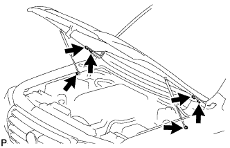
Remove the 2 hood support bolts and disconnect the hood supports.
-
Remove the 4 bolts and hood.
-
-
REMOVE COWL TOP VENTILATOR LOUVER SUB-ASSEMBLY
-
REMOVE FRONT FENDER SPLASH SHIELD SUB-ASSEMBLY LH
-
Remove the 3 bolts and screw.
-
Turn the clip indicated by the arrow in the illustration to remove the front fender splash shield sub-assembly LH.
-
-
REMOVE FRONT FENDER SPLASH SHIELD SUB-ASSEMBLY RH
-
Remove the 3 bolts and 2 screws.
-
Turn the clip indicated by the arrow in the illustration to remove the front fender splash shield sub-assembly RH.
-
-
REMOVE NO. 1 ENGINE UNDER COVER SUB-ASSEMBLY
-
Remove the 10 bolts and No. 1 engine under cover.
-
-
REMOVE NO. 2 ENGINE UNDER COVER
-
Remove the 2 bolts and No. 2 engine under cover.
-
-
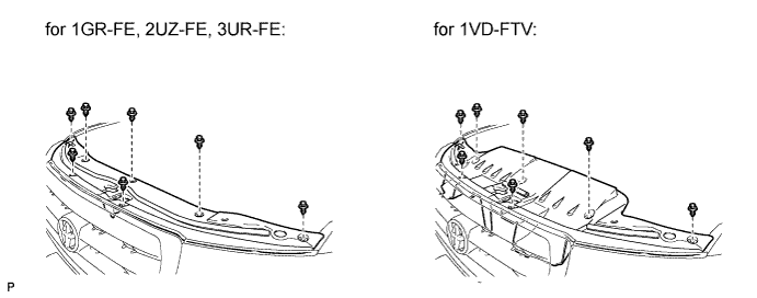
REMOVE UPPER RADIATOR SUPPORT SEAL
-
Remove the 7 clips and radiator support seal.
-
-
REMOVE RADIATOR GRILLE
-

Text in Illustration *1 Protective Tape Put protective tape around the radiator grille assembly.
-
Remove the 3 screws.
-
Detach the 2 clips and 8 claws, and remove the radiator grille assembly.
-
w/ Wide View Front Monitor System:
-
Disconnect the connector.
-
-
-
REMOVE FRONT BUMPER COVER
-
for Standard Click here
-
w/ Winch Click here
-
-
DRAIN ENGINE COOLANT
CAUTION:
Do not remove the radiator cap while the engine and radiator are still hot. Pressurized, hot engine coolant and steam may be released and cause serious burns.
Text in Illustration *1 Radiator Reservoir *2 Radiator Cap *3 Radiator Drain Cock Plug *4 Cylinder Block Water Drain Cock Plug *a for Type A *b for Type B
-
for Type A:
Loosen the radiator drain cock plug and 2 cylinder block water drain cock plugs.
-
for Type B:
Loosen the radiator drain cock plug and cylinder block water drain cock plug.
-
Remove the radiator cap. Then drain the coolant.
Tech Tips
Collect the coolant in a container and dispose of it according to the regulations in your area.
-
for Type A:
Tighten the 2 cylinder block water drain cock plugs.
- Torque:
- 13 N*m { 130 kgf*cm, 9 ft.*lbf }
-
for Type B:
Tighten the cylinder block water drain cock plug.
- Torque:
- 13 N*m { 130 kgf*cm, 9 ft.*lbf }
-
Tighten the radiator drain cock plug by hand.
-
-
REMOVE V-BANK COVER
-
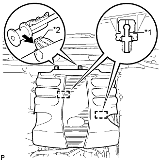
Text in Illustration *1 Pin *2 Hook Raise the front of the V-bank cover to detach the 2 pins. Then remove the 2 V-bank cover hooks from the bracket, and remove the V-bank cover.
-
-
REMOVE TRANSMISSION OIL COOLER AIR DUCT (w/ Air Cooled Transmission Oil Cooler)
-
Remove the 4 bolts and oil cooler air duct.
-
-
REMOVE RADIATOR SIDE DEFLECTOR RH (w/o Air Cooled Transmission Oil Cooler)
-
Using a clip remover, remove the 4 clips and move the side deflector so that the radiator can be removed in a later step.
-
-
REMOVE RADIATOR SIDE DEFLECTOR LH
-
Using a clip remover, remove the 4 clips and move the side deflector so that the radiator can be removed in a later step.
-
-
REMOVE NO. 1 RADIATOR HOSE
-
REMOVE NO. 2 RADIATOR HOSE
-
Detach the clamp and remove the No. 2 radiator hose.
-
-
DISCONNECT OIL COOLER TUBE (w/ Air Cooled Transmission Oil Cooler)
-
Detach the claw to open the flexible hose clamp, and then remove the 2 bolts to disconnect the oil cooler tube from the fan shroud.
-
-
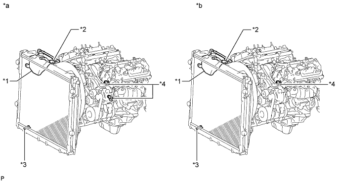
REMOVE FAN SHROUD
-
Loosen the 4 nuts holding the fluid coupling fan.
-
Remove the fan and generator V-belt Click here.
-
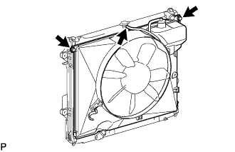
Disconnect the reservoir hose from the upper side of the radiator tank.
-
Remove the 2 bolts holding the fan shroud.
-
Remove the 4 nuts of the fluid coupling fan, and then remove the shroud together with the coupling fan.
Note
Be careful not to damage the radiator core.
-
Remove the fan pulley from the water pump.
-
-
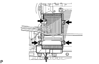
DISCONNECT INLET OIL COOLER HOSE (for Automatic Transmission)
-
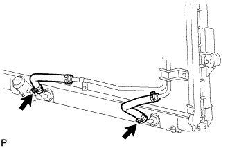
Disconnect the oil cooler hose.
-
-
DISCONNECT OUTLET OIL COOLER HOSE (for Automatic Transmission)
-
Disconnect the oil cooler hose.
-
-
REMOVE RADIATOR ASSEMBLY
-
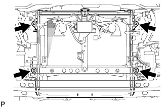
Remove the 4 bolts and radiator.
-
-
DRAIN ENGINE OIL
-
Remove the oil filler cap.
-
Remove the 2 bolts and No. 2 engine under cover seal.
-
Remove the oil pan drain plug and gasket, and drain the engine oil into a container.
-
Install a new gasket and the oil pan drain plug.
- Torque:
- 40 N*m { 408 kgf*cm, 30 ft.*lbf }
-
Install the No. 2 engine under cover seal with the 2 bolts.
- Torque:
- 10 N*m { 102 kgf*cm, 7 ft.*lbf }
-
-
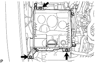
REMOVE AIR CLEANER CAP AND HOSE
-
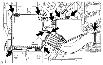
Remove the air cleaner cap and hose.
-
Disconnect the mass air flow meter connector, vacuum hose and ventilation hose and detach the clamp.
-
Loosen the clamp.
-
Unfasten the 4 hook clamps, and then remove the bolt and the air cleaner cap and hose.
-
-
-
REMOVE AIR CLEANER CASE SUB-ASSEMBLY
-
Remove the air cleaner filter element.
-
Remove the 3 bolts and air cleaner case.
-
-
REMOVE AIR TUBE ASSEMBLY (w/ Secondary Air Injection System)
-
Disconnect the No. 3 air hose.
-
for Bank 1 Side:
Remove the bolt and disconnect the air tube assembly from the emission control valve set.
-
for Bank 2 Side:
Remove the 2 bolts and disconnect the air tube assembly from the No. 2 emission control valve set.
-
-
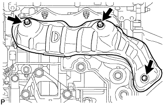
REMOVE INTAKE AIR SURGE TANK
-
Disconnect the throttle body connector.
-
Disconnect the No. 4 water by-pass hose.
-
Disconnect the No. 5 water by-pass hose.
-
Disconnect the purge line hose.
-
Disconnect the No. 1 vacuum switching valve connector.
-
Disconnect the No. 1 PCV hose.
-
Remove the 2 bolts and throttle body bracket.
-
Detach the 2 wire harness clamps and remove the bolt and bracket.
-
Detach the wire harness clamp.
-
Remove the 2 bolts and No. 1 surge tank stay.
-
for Manual Transmission:
Remove the nut and disconnect the clutch flexible hose bracket.
-
Remove the 2 bolts and No. 2 surge tank stay.
-
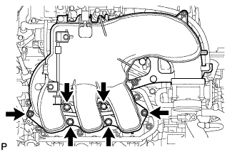
Remove the 2 nuts, 4 bolts and intake air surge tank.
-
Remove the gasket.
-
-
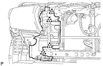
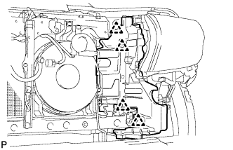
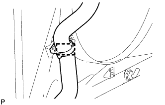
DISCONNECT ENGINE WIRE
-
Remove the junction block cover.
-
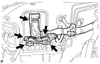
Disconnect the ECM connector Click here.
-
Detach the wire harness clamp.
-
Disconnect the 4 connectors from the junction block.
-
Remove the engine room relay block cover.
-
Remove the bolt and disconnect the ground wire from the bracket.
-
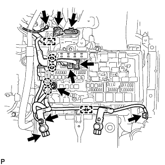
w/ Secondary Air Injection System:
Disconnect the 2 air injection control driver connectors and detach the clamp.
-
Disconnect the 2 connectors and 2 clips from the engine room junction block.
-
Remove the nut and disconnect the wire and 2 clips from the engine room junction block.
-
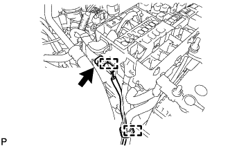
Remove the nut and disconnect the wire from the positive (+) battery cable.
-
Disconnect the cable from the positive (+) battery terminal.
-
Remove the bolt and detach the wire harness clamp, and then disconnect the ground wire from the body.
-
Disconnect the connector and detach the 2 clamps.
-
w/ Winch:
Remove the 2 bolts and winch ground wire.
-
Disconnect the power steering switch connector and detach the clamp.
-
w/ Secondary Air Injection System:
Disconnect the air pump connector and detach the clamp.
-
-
REMOVE HEATED OXYGEN SENSOR (for Bank 1 Sensor 2)
-
Disconnect the sensor connector.
-
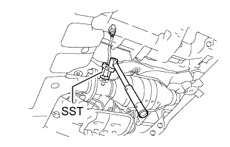
Using SST, remove the sensor.
- SST
- 09224-00010
-
-
REMOVE TAILPIPE ASSEMBLY
-
Remove the bolt, clamp and gasket.
-
Remove the tailpipe from the 2 exhaust pipe supports.
-
-
REMOVE CENTER EXHAUST PIPE ASSEMBLY
-
Remove the 4 bolts and 2 compression springs.
-
Remove the center exhaust pipe from the 3 exhaust pipe supports.
-
Remove the 2 gaskets from the front exhaust pipe and front No. 2 exhaust pipe.
-
-
REMOVE FRONT NO. 2 EXHAUST PIPE ASSEMBLY
-
Disconnect the heated oxygen sensor connector.
-
Remove the 2 nuts and front exhaust pipe.
-
Remove the gasket from the front exhaust pipe.
-
-
REMOVE HEATED OXYGEN SENSOR (for Bank 2 Sensor 2)
-
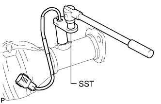
Using SST, remove the sensor.
- SST
- 09224-00010
-
-
REMOVE FRONT EXHAUST PIPE ASSEMBLY
-
Disconnect the heated oxygen sensor connector.
-
Remove the 2 nuts and front exhaust pipe.
-
Remove the gasket from the front exhaust pipe.
-
-
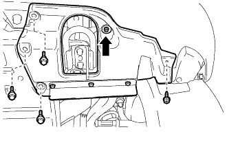
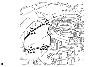
REMOVE FRONT FENDER APRON TRIM PACKING A
-
Remove the 3 clips and front fender apron trim packing A.
-
-
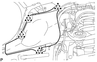
REMOVE FRONT FENDER APRON TRIM PACKING B
-
w/ KDSS:
Remove the 3 clips and front fender apron trim packing B.
-
w/o KDSS:
Remove the 4 clips and front fender apron trim packing B.
-
-
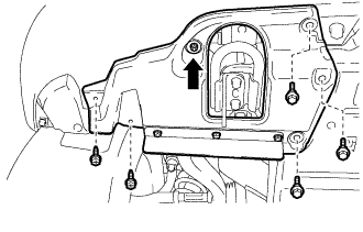
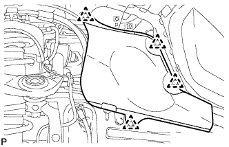
REMOVE FRONT FENDER APRON TRIM PACKING C
-
Remove the 4 clips and front fender apron trim packing C.
-
-
REMOVE FRONT FENDER APRON TRIM PACKING D
-
Remove the 4 clips and front fender apron trim packing D.
-
-
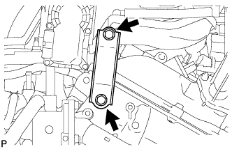
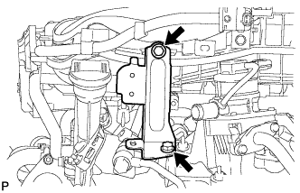
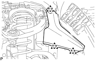
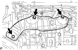
REMOVE MANIFOLD STAY
-
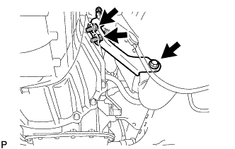
Remove the 3 bolts and manifold stay.
-
-
REMOVE AIR TUBE (w/ Secondary Air Injection System)
-
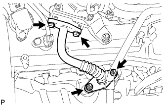
Remove the 2 bolts, 2 nuts and air tube.
-
Remove the 2 gaskets.
Note
Be careful not to damage the installation surface of the gaskets.
-
-
DISCONNECT NO. 2 STEERING INTERMEDIATE SHAFT
-
for Manual Tilt and Manual Telescopic Steering Column: Click here
-
for Power Tilt and Power Telescopic Steering Column: Click here
-
-
REMOVE NO. 1 EXHAUST MANIFOLD HEAT INSULATOR
-
Remove the 3 bolts and heat insulator.
-
-
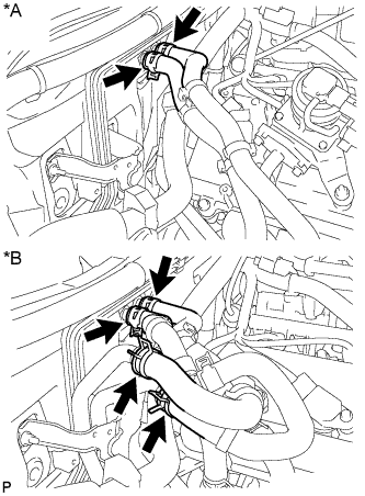
REMOVE EXHAUST MANIFOLD SUB-ASSEMBLY RH
-
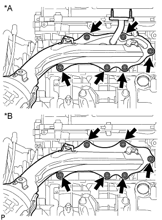
Text in Illustration *A w/ Secondary Air Injection System *B w/o Secondary Air Injection System Disconnect the air fuel ratio sensor connector.
-
Remove the 6 nuts, exhaust manifold sub-assembly RH and gasket.
-
-
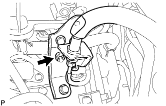
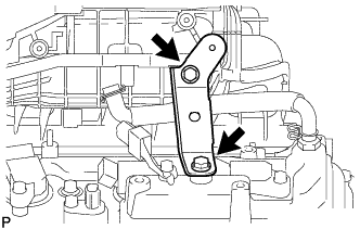
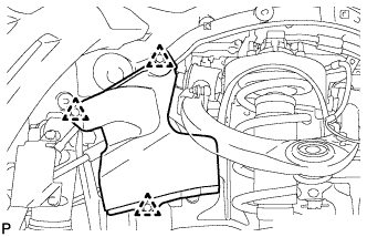
REMOVE NO. 2 MANIFOLD STAY
-
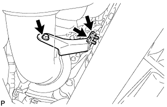
Remove the 3 bolts and No. 2 manifold stay.
-
-
REMOVE NO. 2 AIR TUBE (w/ Secondary Air Injection System)
-
Remove the 2 bolts, 2 nuts and No. 2 air tube.
-
Remove the 2 gaskets.
Note
Be careful not to damage the installation surface of the gaskets.
-
-
REMOVE NO. 2 EXHAUST MANIFOLD HEAT INSULATOR
-
Remove the 3 bolts and heat insulator.
-
-
REMOVE EXHAUST MANIFOLD SUB-ASSEMBLY LH
-
Text in Illustration *A w/ Secondary Air Injection System *B w/o Secondary Air Injection System Disconnect the air fuel ratio sensor connector.
-
Remove the 6 nuts, exhaust manifold sub-assembly LH and gasket.
-
-
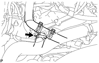
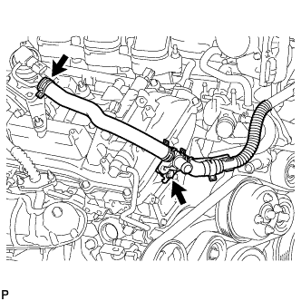
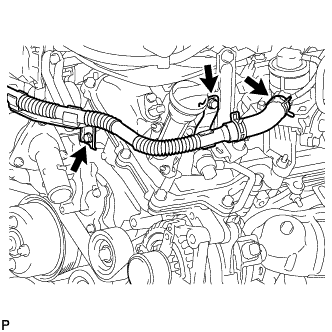
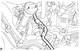
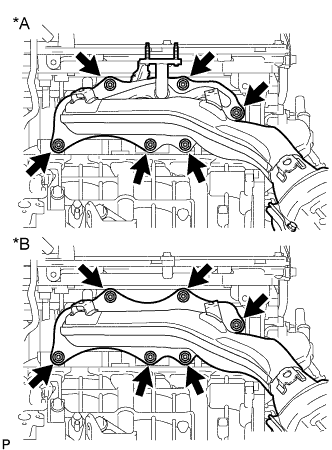
DISCONNECT WATER HOSE SUB-ASSEMBLY
-
Text in Illustration *A w/o Rear Heater *B w/ Rear Heater Disconnect the water hoses.
-
-
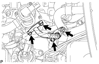
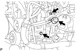
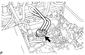
DISCONNECT VANE PUMP ASSEMBLY
-
Disconnect the connector.
-
Detach the wire harness clamp.
-
Remove the 2 bolts and disconnect the vane pump.
-
-
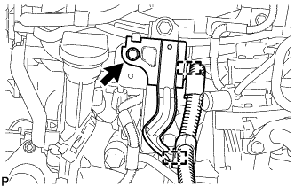
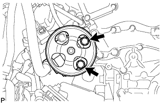
REMOVE GENERATOR ASSEMBLY
-
Disconnect the generator connector.
-
Open the terminal cap.
-
Remove the nut and disconnect the generator wire from terminal B.
-
Remove the bolt and disconnect the wire harness clamp bracket.
-
Remove the bolt and disconnect the generator bracket.
-
Remove the 2 bolts and generator.
-
Remove the bolt and generator bracket.
-
-
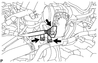
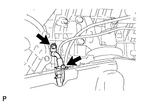
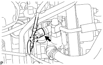
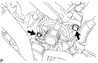
DISCONNECT NO. 1 COOLER REFRIGERANT DISCHARGE HOSE
-
Remove the bolt and disconnect the discharge hose from the cooler compressor.
-
Remove the O-ring from the discharge hose.
Note
Seal the openings of the disconnected parts using vinyl tape to prevent moisture and foreign matter from entering them.
-
-
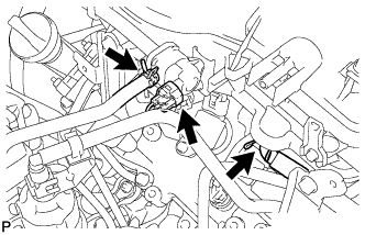
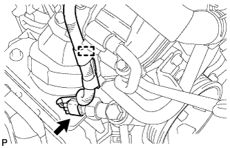
DISCONNECT SUCTION HOSE SUB-ASSEMBLY
-
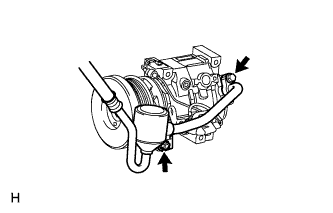
Remove the 2 bolts and disconnect the suction hose from the cooler compressor.
-
Remove the O-ring from the suction hose.
Note
Seal the openings of the disconnected parts using vinyl tape to prevent moisture and foreign matter from entering them.
-
-
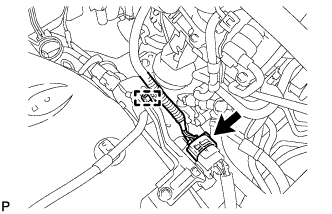
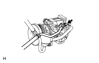
REMOVE COOLER COMPRESSOR ASSEMBLY
-
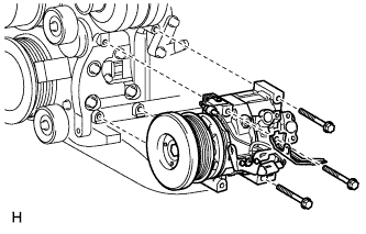
Disconnect the connector.
-
Remove the 3 bolts and cooler compressor.
-
-
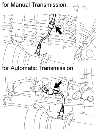
DISCONNECT NO. 1 AND NO. 2 FUEL PIPES
-
Disconnect the No. 1 and No. 2 fuel pipes Click here.
-
-
REMOVE MANUAL TRANSMISSION ASSEMBLY (for Manual Transmission)
-
REMOVE AUTOMATIC TRANSMISSION ASSEMBLY (for Automatic Transmission)
-
REMOVE REAR NO. 1 ENGINE MOUNTING INSULATOR
Tech Tips
Only perform this procedure when replacement of the engine mounting insulator is necessary.
-
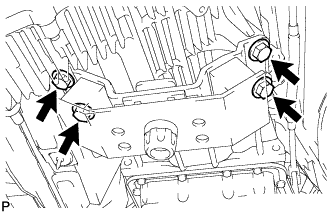
Remove the 4 bolts and rear engine mounting insulator from the transmission.
-
-
DISCONNECT NO. 1 OIL COOLER HOSE TUBE SUB-ASSEMBLY (for Automatic Transmission)
-
Remove the 2 bolts and cooler hose tube.
-
-
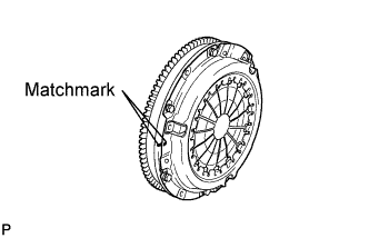
REMOVE CLUTCH COVER ASSEMBLY (for Manual Transmission)
-
Put matchmarks on the clutch cover and flywheel.
-
Loosen each set bolt one turn at a time until spring tension is released.
-
Remove the 6 set bolts, and pull off the clutch cover.
Note
Do not drop the clutch disc.
-
-
REMOVE CLUTCH DISC ASSEMBLY (for Manual Transmission)
Note
Keep the lining part of the clutch disc, pressure plate and surface of the flywheel away from oil and foreign matter.
-
REMOVE FLYWHEEL SUB-ASSEMBLY (for Manual Transmission)
-
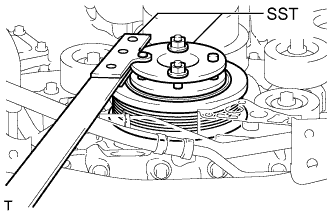
Using SST, hold the crankshaft.
- SST
- 09213-54015 ( 91651-60855 )
- 09330-00021
-
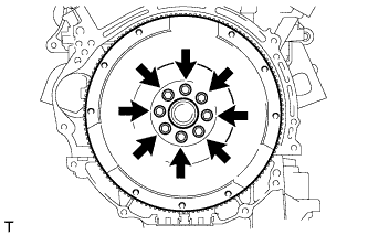
Remove the 8 bolts and flywheel.
Note
Do not reuse the bolts.
-
-
REMOVE DRIVE PLATE AND RING GEAR SUB-ASSEMBLY (for Automatic Transmission)
-
Using SST, hold the crankshaft.
- SST
- 09213-54015 ( 91651-60855 )
- 09330-00021
-
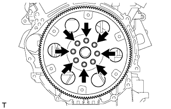
Remove the 8 bolts, rear spacer, drive plate and front spacer.
Note
Do not reuse the bolts.
-
-
INSTALL ENGINE HANGER
-
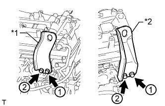
Text in Illustration *1 No. 1 Engine Hanger *2 No. 2 Engine Hanger Install 2 engine hangers with 4 bolts as shown in the illustration.
- Torque:
- 33 N*m { 337 kgf*cm, 24 ft.*lbf }
Tech Tips
No. 1 Engine Hanger 12281-31110 No. 2 Engine Hanger 12282-31140 Bolt 91671-C0830
-
-
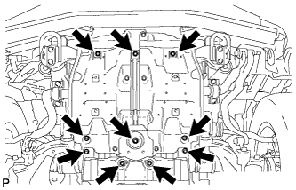
REMOVE ENGINE ASSEMBLY
-
Attach an engine sling device and hang the engine with a chain block.
-
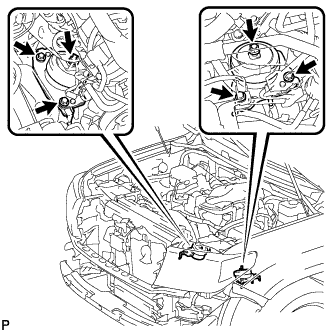
Remove the 2 nuts and 4 bolts from the front engine mounting insulator LH and RH.
-
Lift the engine out of the vehicle carefully.
Note
-
Make sure the engine is clear of all wiring and hoses.
-
With the exception of installing the engine assembly to an engine stand or removing the engine assembly from an engine stand, do not perform any work on the engine while it is suspended, as doing so is dangerous.
-
Pay attention to the angle of the sling device as the engine assembly or engine hangers may be damaged or deformed if the angle is incorrect.
-
-
Remove the front engine mounting insulator LH and RH.
-
Place the engine onto a work bench.
-
-
INSTALL ENGINE STAND
-
Install the engine onto an engine stand with bolts.
-
Remove the 4 bolts and 2 engine hangers.
-
-
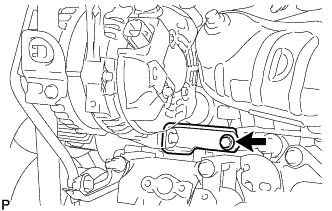
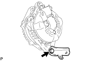
REMOVE FRONT NO. 2 ENGINE MOUNTING BRACKET LH
-
Remove the bolt and front No. 2 engine mounting bracket LH.
-