DIESEL THROTTLE BODY INSTALLATION

Note
Disconnect the cable from the negative (-) battery terminal to clear the diesel throttle valve fully closed position learned value.
-
INSTALL DIESEL THROTTLE BODY ASSEMBLY LH
-
Install a new gasket to the intake pipe.
-
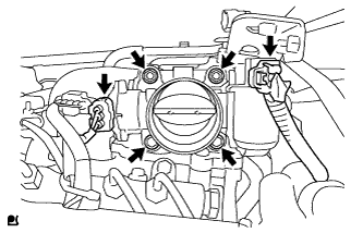
Install the throttle body with the 2 bolts and 2 nuts.
- Torque:
- 21 N*m { 214 kgf*cm, 15 ft.*lbf }
-
Connect the throttle position sensor connector.
-
Connect the throttle motor connector.
-
-
INSTALL DIESEL THROTTLE BODY ASSEMBLY RH
-
Install a new gasket to the intake pipe.
-
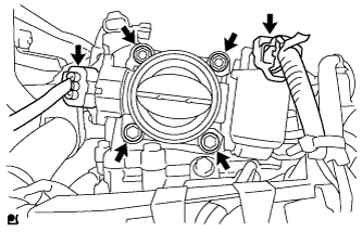
Install the throttle body with the 2 bolts and 2 nuts.
- Torque:
- 21 N*m { 214 kgf*cm, 15 ft.*lbf }
-
Connect the throttle position sensor connector.
-
Connect the throttle motor connector.
-
-
INSTALL TUBE CONNECTOR TO FLEXIBLE HOSE TUBE (for Manual Transmission)
-
Temporarily install the flare nut of the tube connector to flexible hose tube to the clutch tube to release cylinder 2 way by hand.
-
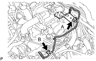
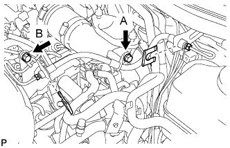
Temporarily install the tube connector to flexible hose tube with the 2 bolts.
-
Tighten the bolt labeled A.
- Torque:
- 20 N*m { 204 kgf*cm, 15 ft.*lbf }
Note
Tighten the bolt labeled B after installing the clutch hose.
-
-
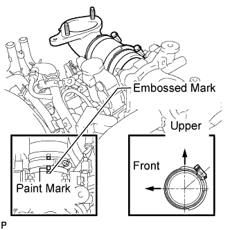
INSTALL AIR TUBE SUB-ASSEMBLY LH
-
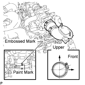
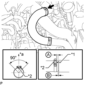
Install the air tube to the throttle body.
-
Align the embossed mark of the throttle body with the paint mark of the No. 4 air hose.
-
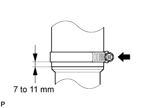
Tighten the hose clamp so that it is 7 to 11 mm (0.276 to 0.433 in.) from the end of the hose as shown in the illustration.
- Torque:
- 6.3 N*m { 64 kgf*cm, 56 in.*lbf }
-
-
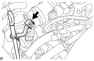
INSTALL CLUTCH HOSE (for Manual Transmission)
-
Connect the clutch hose to the air tube with the bolt labeled A.
-
Temporarily install the clutch hose to the clutch master cylinder tube to flexible hose tube and tube connector to flexible hose tube, and fix it in place with the 2 clips.
- Torque:
- 20 N*m { 204 kgf*cm, 15 ft.*lbf }
-
Tighten the bolt labeled B.
- Torque:
- 20 N*m { 204 kgf*cm, 15 ft.*lbf }
-
Tighten the flexible hose tube.
Note
-
Do not bend or damage the flexible hose tube.
-
Do not allow any foreign matter such as dirt and dust to enter the flexible hose tube from the connecting points.
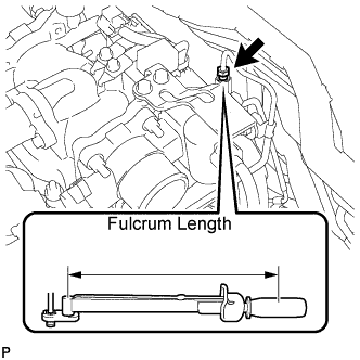
Tech Tips
-
Use a torque wrench with a fulcrum length of 30 cm (11.8 in.). If using a torque wrench with a length that is not 30 cm (11.8 in.), calculate the torque specification for the torque wrench and SST based on the "without SST" torque specification Click here.
-
Make sure union nut wrench and the wrench are connected in a straight line.
-
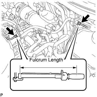
Using a 10 mm union nut wrench, tighten the 2 flare nuts of the flexible hose tube.
- Torque:
- without union nut wrench
- 15 N*m { 154 kgf*cm, 11 ft.*lbf }
- with union nut wrench
- 14 N*m { 141 kgf*cm, 10 ft.*lbf }
-
Using a 10 mm union nut wrench, tighten the flare nut of the flexible hose tube.
- Torque:
- without union nut wrench
- 15 N*m { 154 kgf*cm, 11 ft.*lbf }
- with union nut wrench
- 14 N*m { 141 kgf*cm, 10 ft.*lbf }
-
-
-
INSTALL AIR TUBE SUB-ASSEMBLY RH
-
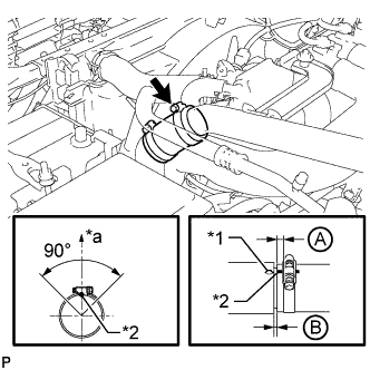
Install the air tube to the throttle body.
-
Align the embossed mark of the throttle body with the paint mark of the No. 4 air hose.
-
Tighten the hose clamp so that it is 7 to 11 mm (0.276 to 0.433 in.) from the end of the hose as shown in the illustration.
- Torque:
- 6.3 N*m { 64 kgf*cm, 56 in.*lbf }
-
-
CONNECT NO. 2 ENGINE OIL LEVEL DIPSTICK GUIDE
-
Connect the dipstick guide with the bolt.
- Torque:
- 10 N*m { 102 kgf*cm, 7 ft.*lbf }
-
-
INSTALL NO. 1 COOL AIR INLET (w/o Intercooler)
-
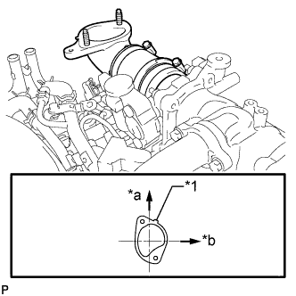
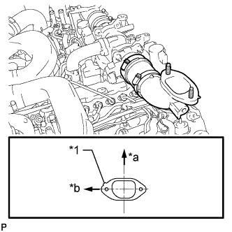
Text in Illustration *1 Protrusion *a Front *b RH Side Install a new gasket to the air tube RH.
Tech Tips
Install the gasket with the protrusion facing as shown in the illustration.
-
Install the No. 1 cool air inlet with the 3 nuts and bolt.
- Torque:
- 21 N*m { 214 kgf*cm, 15 ft.*lbf }
-
Connect the vacuum hose, intake air temperature sensor connector and turbo pressure sensor connector.
-
Text in Illustration *1 Protrusion *2 Paint Mark *a Top Connect the No. 1 air hose to the No. 1 cool air inlet.
-
Tighten the No. 1 air hose clamp.
- Torque:
- 6.3 N*m { 64 kgf*cm, 56 in.*lbf }
Tech Tips
-
Align the paint mark of the air hose with the protrusion and push on the air hose so that distance B is 0 to 3 mm (0 to 0.118 in.).
-
Position the clamp so that distance A is 2 to 6 mm (0.0787 to 0.236 in.).
-
Make sure the direction of the hose clamp is as shown in the illustration.
-
-
INSTALL NO. 2 COOL AIR INLET (w/o Intercooler)
-
Text in Illustration *1 Protrusion *a Front *b LH Side Install a new gasket to the air tube LH.
Tech Tips
Install the gasket with the protrusion facing as shown in the illustration.
-
Install the No. 2 cool air inlet with the 3 nuts and bolt.
- Torque:
- 21 N*m { 214 kgf*cm, 15 ft.*lbf }
-
Text in Illustration *1 Protrusion *2 Paint Mark *a Top Connect the No. 2 air hose to the No. 2 cool air inlet.
-
Tighten the No. 2 air hose clamp.
- Torque:
- 6.3 N*m { 64 kgf*cm, 56 in.*lbf }
Tech Tips
-
Align the paint mark of the air hose with the protrusion and push on the air hose so that distance B is 0 to 3 mm (0 to 0.118 in.).
-
Position the clamp so that distance A is 2 to 6 mm (0.0787 to 0.236 in.).
-
Make sure the direction of the hose clamp is as shown in the illustration.
-
-
INSTALL INTERCOOLER ASSEMBLY (w/ Intercooler)
-
FILL BRAKE FLUID RESERVOIR
-
Fill the reservoir with brake fluid.
Brake Fluid SAE J1703 or FMVSS No. 116 DOT 3
-
-
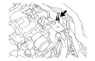
BLEED CLUTCH LINE
-
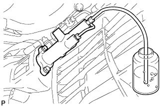
Remove the release cylinder bleeder plug cap.
-
Connect a vinyl tube to the bleeder plug.
-
Depress the clutch pedal several times, and then loosen the bleeder plug while the pedal is depressed.
-
When fluid no longer comes out, tighten the bleeder plug, and then release the clutch pedal.
-
Repeat the previous 2 steps until all the air in the fluid is completely bled.
-
Tighten the bleeder plug.
- Torque:
- 11 N*m { 110 kgf*cm, 8 ft.*lbf }
-
Install the bleeder plug cap.
-
Check that all the air has been bled from the clutch line.
-
-
CHECK FLUID LEVEL IN RESERVOIR
-
Check the fluid level.
If the brake fluid level is low, check for leaks and inspect the disc brake pad. If necessary, refill the reservoir with brake fluid after repair or replacement.
Brake fluid SAE J1703 or FMVSS No. 116 DOT 3
-
-
INSPECT FOR CLUTCH FLUID LEAK
-
CONNECT CABLE TO NEGATIVE BATTERY TERMINAL
Note
When disconnecting the cable, some systems need to be initialized after the cable is reconnected Click here.
-
CHECK DIESEL THROTTLE BODY ASSEMBLY
-
Inspect the diesel throttle valve.
-
Turn the engine switch on (IG).
-
Turn the engine switch off and wait 5 seconds.
Tech Tips
Be sure to turn off the engine switch before performing this inspection. The fully closed position of the diesel throttle valve is learned when the engine switch is turned off.
-
Connect the intelligent tester to the DLC3.
-
Turn the engine switch on (IG).
-
Turn the intelligent tester on.
-
Enter the following menus: Powertrain / Engine / Data List / Diesel Throttle / Throttle Sensor Volt % and Throttle Sensor #2 Volt %.
-
Check that the value of "Throttle Sensor Volt %, Throttle Sensor #2 Volt %" is within the specification.
Standard Value Tester Display Specified Condition Throttle Sensor Volt % 60 to 80% Throttle Sensor #2 Volt % If the result is not as specified, replace the throttle body.
-
Enter the following menus: Powertrain / Engine / Data List / All Data / Throttle Close Learning Val.
-
Check that the value of "Throttle Close Learning Val" is within the specification.
Standard Throttle Valve Fully Closed Tester Display Specified Condition Throttle Close Learning Val. 14.25 to 21.25 deg If the result is not as specified, replace the throttle body.
-
-
-
PERFORM DIESEL THROTTLE BODY INITIALIZATION