ECD SYSTEM (w/o DPF) Lack of Power or Hesitation
DESCRIPTION
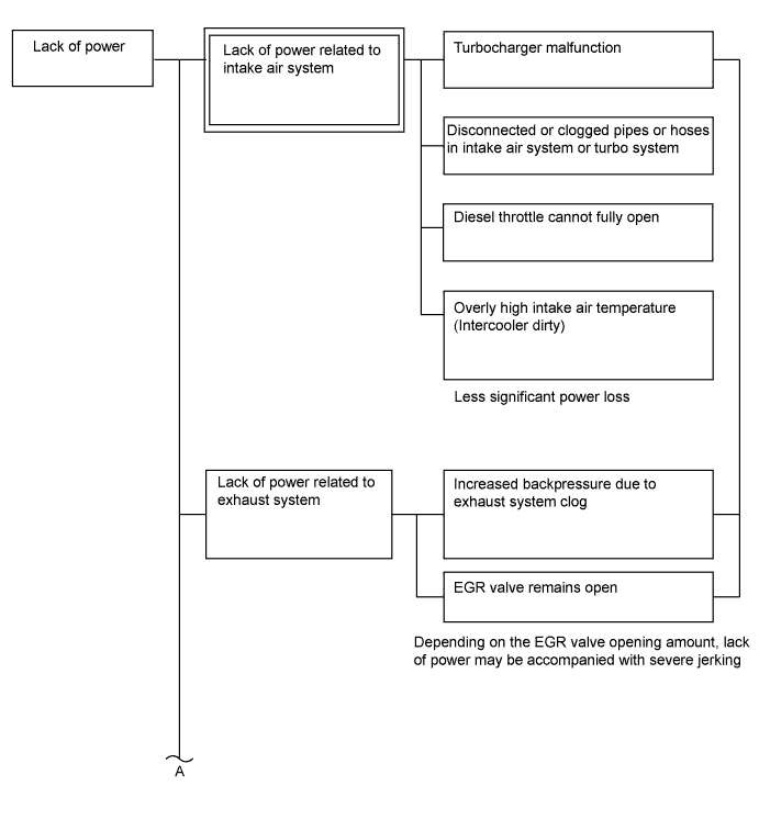
| Malfunction Condition | Main Trouble Area | Related Trouble Area |
|---|---|---|
|
|
|
Tech Tips
-
Specified values in the following troubleshooting flowchart are for reference only. Variations in the Data List values may occur depending on the measuring conditions or the vehicle age. Do not judge the vehicle to be normal even when the Data List values indicate a standard level. There are possibly some concealed factors of the malfunction.
-
Check that the vehicle has not been modified in any way prior to the vehicle inspection.
-
This troubleshooting procedure checks for the cause of an obvious lack of engine power (e.g. the vehicle speed does not reach the target speed in the high speed range) while the vehicle is being driven.
-
Faults and Symptoms of Common Rail Diesel Components
-
Engine Control
Mass Air Flow Meter Component Mass air flow meter Main fault Decrease in performance (foreign matter is stuck) Symptoms Lack of power, black smoke Data List MAF Tech Tips
The maximum fuel injection volume is controlled according to the output from the mass air flow meter.
Intake System Component Intake system Symptom: Main fault
-
Lack of power (No black smoke): Air filter blockage, Air duct is crushed/leaking
-
Black smoke (No lack of power): Leakage between the turbo and the intake manifold
Data List
-
MAP (inside intake air pressure)
-
Target Booster Pressure
When the accelerator is fully depressed, if the MAP is 20 kPa lower than Target Booster Pressure for more than 5 seconds then a lack of power will be felt.
Turbocharger System Component Turbocharger system Main fault
-
Air leak in the turbocharged air passage
-
Turbo motor driver not operating well
-
Turbocharger (turbine, bearing)
Symptoms Lack of power (when vehicle starting, when heavy load)
(Black smoke is not emitted when racing while vehicle stopped)
Data List MAP (inside intake air pressure), Target Booster Pressure
-
When the accelerator is fully depressed, if MAP is 20 kPa lower than Target Booster Pressure for more than 5 seconds then a lack of power will be felt.
-
With the ignition switch ON or idling, MAP = Atmospheric Pressure (standard atmospheric pressure = 101 kPa). When the engine speed is about 1500 rpm or more, the turbocharger starts to take effect and the MAP becomes higher than atmospheric pressure.
-
Atmospheric pressure increases 1 kPa each time altitude increases by 100 m, and is also affected by the current weather conditions.
VN Turbo Command
-
Using the Active Test "Test the Turbo Charger Step Motor", check the drive rod movement.
-
Check the drive rod movement when the ignition switch is turned from ON to off.
Diagnostic Point
-
Use Active Test of Test the Turbo Charger Step Motor, check the drive rod's movement.
-
Check the drive rod's movement when turning the ignition switch off from idling.
Exhaust System Component Exhaust system Main fault Blockage Symptoms Lack of power (high engine speed, when heavy load) Data List MAP (inside intake air pressure), Target Booster Pressure
When the accelerator is fully depressed, if the MAP is 20 kPa lower than Target Booster Pressure for more than 5 seconds then a lack of power will be felt.
Glow System Component Glow system Main fault Open circuit, glow plug relay fault Symptoms Difficult to start, rough idle, knocking, white smoke (when cold) Data List Check the glow plug indicator light Diagnostic Point Try to measure the resistance of the glow plug Engine - 1 Component Engine Main fault Damaged, Seized up Symptoms Cannot crank, crank speed is low, strange noise Engine - 2 Component Engine Main fault Loss of compression Symptoms Rough idle (lack of power always) Data List Engine Speed of Cyl#
-
When cranking during the "Check the Cylinder Compression" Active Test, if there is a high speed cylinder, approx. 100 rpm more than the other cylinders, that cylinder loose compression.
Injection Feedback Val
-
If Injection Feedback Val is more than 3 mm3/st, the cylinder may have a fault.
-
-
Diesel Injection
Fuel Supply Pump Component Fuel supply pump Main fault - Symptoms Difficult to start, engine stalling, rough idle, lack of power Data List Fuel Press, Target Common Rail Pressure, Target Pump SCV Current
-
At a stable condition (e.g. Idling), Fuel Press is within +/-5000 kPa of "Target Common Rail Pressure".
-
If the fuel pressure is 20000 kPa below the target pressure then a lack of power will be felt.
-
If the fuel pressure is below 25000 kPa then idling will be rough.
-
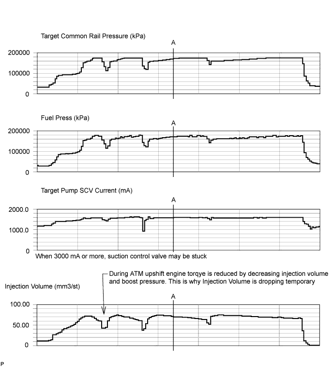
If Target Pump SCV Current is 3000 mA or more, the suction control valve may be stuck.
Tech Tips
-
The fuel pressure changes at engine starting, but is approx. 25000 kPa at engine start after the engine is warmed up.
-
When Target Pump SCV Current is 3000 mA or more, the suction control valve has a tendency to become stuck.
Diagnostic Trouble Code Even if Fuel Press is less than Target Common Rail Pressure, a DTC will not be stored. Fuel Filter Component Fuel filter Main fault Blockage Symptoms Difficult to start, engine stalling, rough idle, lack of power Data List Fuel Press, Target Common Rail Pressure
-
At a stable condition (e.g. Idling), the fuel pressure is within +/-5000 kPa of "Target Common Rail Pressure ".
-
If the fuel pressure is 20000 kPa below the target pressure then a lack of power will be felt.
-
If the fuel pressure is below 25000 kPa then idling will be rough.
Tech Tips
The fuel pressure changes at engine starting, but is approx. 25 MPa at engine start after the engine is warmed up.
Diagnostic Trouble Code Even if Fuel Press is less than Target Common Rail Pressure, a DTC will not be stored. Fuel Injector Component Fuel injector Main fault Blockage Symptoms Rough idle, lack of power, black smoke, white smoke, knocking Data List Injection Feedback Val
-
When an Injection Feedback Val is more than 3 mm3/st, the cylinder is not normal. This can be read after idling for 1 minute with the engine warmed up (engine coolant temperature is more than 70°C (158°F)).
Pressure Limiter Component Pressure limiter Main fault Does not completely close Symptoms Difficult to start, engine stall, rough idle, lack of power Injector Driver (EDU) Component Injector Driver (EDU) Main fault Circuit fault: The fuel injector does not open. Symptoms Difficult to start, rough idle, lack of power, black smoke, white smoke, knocking Data List Same as fuel injector Diagnostic Trouble Code When the EDU has a fault, some DTCs may be storedr. Fuel Pressure Sensor Component Fuel pressure sensor Main fault Open circuit, decrease in performance (foreign matter is stuck) Symptoms Difficult to start, rough idle, engine stall, lack of power Data List Fuel Press, Target Common Rail Pressure
-
At a stable condition (e.g. Idling), Fuel Press is within +/-5000 kPa of "Target Common Rail Pressure".
Diagnostic Code When the fuel pressure sensor has a fault, some DTCs may be stored. Irregular Fuel Component Irregular fuel Main fault - Symptoms Difficult to start, rough idle (especially when cold) -
-
Diesel EGR
EGR System Component EGR system Main fault
-
Does not move smoothly
-
Does not close fully
Symptoms
-
Rough Idle
-
EGR valve stuck closed: A loud turbocharger sound.
-
EGR valve stuck open: Difficult to start (does not stall), black smoke, lack of power, jerking (If there is an excess in the quantity of EGR and there is a heavy load, when the vehicle starts moving, a lack of power will be felt. Also, when racing the engine, there will be some black smoke).
Data List Actual EGR Valve Pos., Target EGR Pos.
-
Generally, Actual EGR Valve Pos. = Target EGR Pos. +/-5% (fully closed 0%, fully open 100%)
-
Using EGR valve Active Test, check whether Actual EGR Valve Pos. follows Target EGR Pos. (The engine coolant temperature and intake air temperature should be considered when a malfunction occurs).
-
EGR valve is fully closed when the ignition switch is ON (engine stopped).
-
EGR valve opens to a halfway point at idling after engine warmed up.
-
When the EGR valve does not close, MAF (Mass Air Flow) decreases when the vehicle is accelerated at full throttle. MAP also decreases in comparison to Target Booster Pressure, however there is not a large difference.
EGR Close Lrn. Val., EGR Close Lrn. Status
-
In cases when EGR Close Lrn. Status. is NG or EGR Close Lrn. Val. is out of the normal range (3.5 to 4.5 V), it is possible that the EGR valve cannot completely close.
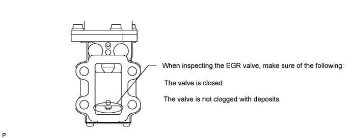
Inspect EGR valve assembly
-
-
Diesel Throttle
Diesel Throttle System Component Diesel throttle system Main fault Stuck, does not move smoothly Symptoms
-
Stuck closed: Lack of power, difficult to start, rough idle, engine stall, black smoke. It may occur when stuck almost fully closed.
-
Stuck open: Turbocharger sound increases. When the engine is stopped, engine vibrations may occur.
Data List
-
Actual Throttle Position (fully closed 100%, fully open 0%)
-
Throttle Motor Duty
Normally operates at 50 +/-20%. If outside the range of 50 +/-40% for a few seconds, the throttle may not be sliding properly.
0%: Open diesel throttle
100%: Close diesel throttle
-
When ignition switch is ON (engine stopped), diesel throttle is fully open. When idling, diesel throttle is at halfway point. When ignition switch is turned ON to off, temporarily closed fully.
-
-
-
Data List Related to Lack of Power
Note
The Data List values in the table are the results of checking one vehicle after warmed up. Only use these values for reference.
-
Engine Control
Engine Speed Data List Judgment of Data List Values Faulty Component Diagnosis Note Engine Speed
-
Idling: 500 to 600 rpm (M/T)
-
Idling: 550 to 650 rpm (A/T)
Crankshaft position sensor When the crankshaft position sensor is malfunctioning, "Engine Speed" is approximately 0 or varies greatly from the actual engine speed. MAP Data List Judgment of Data List Values Faulty Component Diagnosis Note MAP MAP (inside intake air pressure)
-
When the accelerator is fully depressed, if MAP is 20 kPa lower than Target Booster Pressure for more than 5 seconds, a lack of power will be felt.
-
With the ignition switch ON or vehicle idling, MAP is nearly equal to Atmospheric Pressure (standard atmospheric pressure = 101 kPa). Atmospheric pressure increases 1 kPa each time altitude increases by 100 m, and is also affected by the current weather conditions). When the engine speed is about 1500 rpm or more, the turbocharger starts to take effect and MAP becomes higher than atmospheric pressure. The Data List item "Atmosphere Pressure" displays the output of the atmospheric pressure sensor.
VN Turbo Command
-
0%: Fully open vanes (drive rod contracts)
-
Over 90%: Fully closed vanes (drive rod expands)
-
Turbocharger fault
-
Diesel throttle does not open
-
Intake system blocked
-
Exhaust system blocked
-
Inspect while comparing with "Target Booster Pressure".
-
With the accelerator fully open, if the actual Manifold Absolute Pressure (MAP) is low compared to the target booster pressure by at least 20 kPa for 5 seconds or more, a feeling of insufficient power will occur.
Results of real-vehicle check:
-
Ignition switch ON: 99 kPa
-
Cranking: 99 kPa
-
Idling (warm up the engine): 99 kPa (2 minutes after starting the vehicle)
-
Running without load (2500 rpm): 113 kPa
-
Running without load (4000 rpm): 150 kPa
-
Driving with the accelerator fully open at 2000 rpm: 143 kPa
-
Driving with the accelerator fully open at 3000 rpm: 209 kPa
MAF Data List Judgment of Data List Values Faulty Component Diagnosis Note MAF -
-
MAF meter
-
MAF meter circuit
-
Intake system clogging, leaking
-
Exhaust system clogging
-
Turbocharger sub-assembly
-
Leaking or clogging of turbocharger passages
-
EGR valve does not close
-
Based on MAF, the ECM controls the fuel injection volume, injection timing, EGR, etc.
-
If the value is always approximately 0 g/sec.:
-
Mass air flow meter power source circuit is open.
-
VG circuit is open or shorted.
-
If the value is always 200 g/sec. or more:
-
EVG circuit is open.
Results of real-vehicle check:
w/ EGR
-
Ignition switch ON: 1.54 g/sec.
-
Cranking: 15 g/sec.
-
Idling (warm up the engine): 9 g/sec. (2 minutes after starting the vehicle)
-
Running without load (2500 rpm): 80 g/sec.
-
Driving with the accelerator fully open at 2000 rpm: 110 g/sec.
-
Driving with the accelerator fully open at 3000 rpm: 230 g/sec.
Tech Tips
The maximum fuel injection volume is controlled according to the output from the mass air flow meter.
Intake Air Data List Judgment of Data List Values Faulty Component Diagnosis Note Intake Air After a long soak, the engine coolant temperature, intake air temperature, and ambient air temperature are approximately equal. Intake air temperature sensor
-
If the value is -40°C (-40°F) or 140°C (284°F), the sensor circuit is open or shorted.
- Coolant Temp Data List Judgment of Data List Values Faulty Component Diagnosis Note Coolant Temp
-
Engine coolant temperature is approximately equal to intake air temperature after leaving overnight. After warm-up: Engine coolant temperature is 70°C (158°F) or more.
-
In cases when the engine coolant temperature sensor output is obviously higher than the actual engine coolant temperature, when it is cold, there will be difficulty starting due to problems with glow plugs or insufficient fuel injection.
-
In cases when the engine coolant temperature sensor output is obviously lower than the actual engine coolant temperature, when it is warm, there will be difficulty starting (black smoke will also occur) due to an excess of injected fuel.
Engine coolant temperature sensor If the value is -40°C (-40°F) or 140°C (284°F), the sensor circuit is open or shorted. - -
-
Diesel Injection
Target Common Rail Pressure Data List Judgment of Data List Values Faulty Component Diagnosis Note Target Common Rail Pressure - -
-
Inspect the (actual) fuel pressure, comparing it against the common rail target value.
-
Considered normal when the actual fuel pressure is within +/-5000 kPa of the target fuel pressure under stable conditions.
Results of real-vehicle check:
-
Ignition switch ON: 32000 kPa
-
Cranking: 29000 kPa
-
Idling (warm up the engine): 32000 kPa (2 minutes after starting the vehicle)
-
Running without load (2500 rpm): 62000 kPa
-
Running without load (3500 rpm): 80200 kPa
-
Driving with the accelerator fully open at 2000 rpm: 95000 kPa
-
Driving with the accelerator fully open at 3000 rpm: 155000 kPa
Fuel Press Data List Judgment of Data List Values Faulty Component Diagnosis Note Fuel Press
-
In a stable operating condition (e.g. idling), Fuel Press is Target Common Rail Pressure +/-5000 kPa.
-
When the Fuel Press is 20000 kPa lower than Target Common Rail Pressure, a lack of power will be felt.
-
When Fuel Press is lower than 25000 kP, rough idling will occur.
-
If there is a the fuel supply pump (lack of discharge quantity) or pressure limiter (will not fully close) breakdown, the fuel pressure will drop. Also, a blocked fuel filter, leakage from fuel pipes, and an empty fuel tank will also make the fuel pressure drop.
-
When there is a fault with the fuel supply pump, there is a possibility of lack of power, starting trouble, engine stall, rough idle, etc.
-
Fuel Press is the actual common rail fuel pressure.
-
Inspect by comparing the fuel pressure with Target Fuel Pressure.
-
The ECM uses Fuel Press for feedback control of Target Fuel Pressure via the supply pump.
The injection amount is determined based on the injection timing and fuel pressure.
Also, the spray pattern is selected based on the fuel pressure.
Results of real-vehicle check:
-
Ignition switch ON: 0 kPa
-
Cranking: 29000 kPa
-
Idling (warm up the engine): 32000 kPa
-
Running without load (2500 rpm): 62000 kPa
-
Driving with the accelerator fully open at 2000 rpm: 92000 kPa
-
Driving with the accelerator fully open at 3000 rpm: 155000 kPa
Target Pump SCV Current Data List Judgment of Data List Values Faulty Component Diagnosis Note Target Pump SCV Current
-
Idling after warming up, around 923 to 1123 mA. When this value is large, the fuel supply pump is trying to increase the fuel discharge rate.
-
If the value becomes 3000 mA or more, the suction control valve may become stuck.
With this data, component fault not specified, use this data as a reference
-
ECU-calculated value for the suction control valve actuation target current.
-
Value is large when a high fuel pressure is desired.
-
When this deviates from the standard value, it indicates that for some reason, even though the pump is running hard, the actual fuel pressure is inconsistent with the target fuel pressure.
Results of real-vehicle check:
-
Ignition switch ON: 0 mA
-
Cranking: 1200 mA
-
Running without load (2500 rpm): 1300 mA
-
Driving with the accelerator fully open at 2000 rpm: 1440 mA
-
Driving with the accelerator fully open at 3000 rpm: 1560 mA
Injection Feedback Val #1 (to #8) Data List Judgment of Data List Values Faulty Component Diagnosis Note Injection Feedback Val #1 (to #8) Injection Feedback Val:
-
When idling after the engine is warmed up, to make each cylinder engine speed equal, the fuel quantity of each fuel injector is corrected.
-
Cylinders more than 3 mm3/st may have a fault.
Tech Tips
Read the value after one minute of idling after warm up (engine coolant temperature above 70°C (158°F)). This value is only calculated when idling.
-
"Breakdown of injector or lack of compression" of a cylinder with an irregular Injection Feedback Val # value.
-
Do a compression Active Test. If there is a cylinder that is around 100 rpm more than the other cylinders, there is a possibility that that cylinder has a fault.
-
If all the cylinder speeds are even according to the compression Active Test result, then consider the injector of the cylinder that has a fault.
-
With fuel injector faults, there is a possibility of rough idling, lack of power, difficulty starting, black smoke, white smoke and knocking.
With Injection Feedback Val, find the malfunctioning cylinders. However, before replacing the injector, identify the malfunctioning cylinders with a power balance test. - Injection Volume Data List Judgment of Data List Values Faulty Component Diagnosis Note Injection Volume
-
Diagnose the fuel injector faults from the Injection Feedback Val #, Injection Volume at idling.
-
When Injection Volume is more than 10 mm3/st at idle with the engine warmed up and Injection Feedback Val # of all cylinders is less than 2.0 mm3/st, the following malfunctions are possible:
- All cylinder fuel injectors are slightly blocked.
- Fuel filter is blocked.
- Poor quality fuel, increase in engine friction.
All cylinders - Results of real-vehicle check:
-
Cranking: 21 mm3/st
-
Idling (warm up the engine): 6 mm3/st
-
Running without load (2500 rpm): 9 mm3/st
-
Running without load (4700 rpm): 16 mm3/st
-
Driving with the accelerator fully open at 2000 rpm: 50 mm3/st
-
Driving with the accelerator fully open at 3000 rpm: 70 mm3/st
-
-
Diesel Throttle
Actual Throttle Position, Actual Throttle Position #2 Data List Judgment of Data List Values Faulty Component Diagnosis Note Actual Throttle Position
Actual Throttle Position #2
-
When the ignition switch is turned to ON (engine stopped), the diesel throttle is fully open, when the ignition switch is turned from ON to off, it will be fully closed temporarily.
-
During idling, the throttle is open partway.
-
When stuck closed (almost fully closed), there is a possibility of lack of power, rough idling, engine stall, and black smoke.
Throttle valve Actual Throttle Position is the closing percentage of the throttle valve.
-
Fully closed: 100%
-
Fully open: 0%
Tech Tips
There is no connection with the accelerator. However, under full load, the throttle is usually fully open (0%).
Results of real-vehicle check:
-
Ignition switch ON: 0%
-
Cranking: 0%
-
Idling (warm up the engine): 84%
-
Running without load (2500 rpm): 32%
-
Driving with the accelerator fully open at 2000 rpm: 0%
-
Driving with the accelerator fully open at 3000 rpm: 0%
Throttle Motor Duty #1, Throttle Motor Duty #2 Data List Judgment of Data List Values Faulty Component Diagnosis Note Throttle Motor Duty #1
Throttle Motor Duty #2
Normally operates at 50 +/-20%. If 50 +/-40% continues for a few seconds, it is conceivable that the throttle valve is not sliding properly and the MIL will be illuminated.
0%: Drive diesel throttle to open side
100%: Drive diesel throttle to closed side
-
Throttle valve
-
ECM
-
When this value is large but the actual opening angle does not move smoothly, there is an unable to close malfunction.
-
If this value is small but the actual opening angle does not move smoothly, there is an unable to open malfunction.
-
Usually this value is at approx. 50 +/-20%, but momentary jumps outside this range do occur.
Results of real-vehicle check:
-
Ignition switch ON: 61.5%
-
Cranking: 63%
-
Idling (warm up the engine): 37%
-
Running without load (2500 rpm): 53%
-
Driving with the accelerator fully open at 2000 rpm: 62.5%
-
Driving with the accelerator fully open at 3000 rpm: 64%
-
-
Diesel EGR
Target EGR Valve Pos., Target EGR Valve Pos. #2 Data List Judgment of Data List Values Faulty Component Diagnosis Note Target EGR Valve Pos.
Target EGR Valve Pos. #2
- -
-
Fully open: 100%
-
Fully closed: 0%
-
Used for comparison to "Actual EGR Valve Pos".
Results of real-vehicle check:
-
Ignition switch ON: 0%
-
Cranking: 0%
-
Idling (warm up the engine): 43%
-
Running without load (2500 rpm): 22%
-
Driving with the accelerator fully open at 2000 rpm: 0%
-
Driving with the accelerator fully open at 3000 rpm: 0%
Actual EGR Valve Pos., Actual EGR Valve Pos. #2 Data List Judgment of Data List Values Faulty Component Diagnosis Note Actual EGR Valve Pos.
Actual EGR Valve Pos. #2
Generally Actual EGR Valve Pos. = Target EGR Pos. +/-5% (completely closed = 0%, completely open = 100%)
The EGR valve Active Test can be used to check whether the Actual EGR Valve Pos. = Target EGR Pos.
(Take into consideration the temperature of the intake air and the coolant temperature when the malfunction occurs).
Sometimes the malfunction only occurs around a certain temperature. Take into consideration the temperature of the intake air and the coolant temperature when the malfunction occurs.
EGR valve Inspect while comparing to "Target EGR Valve Pos.". Results of real-vehicle check:
-
Ignition switch ON: 0%
-
Cranking: 0%
-
Idling (warm up the engine): 84%
-
Running without load (2500 rpm): 34%
-
Driving with the accelerator fully open at 2000 rpm: 0%
-
Driving with the accelerator fully open at 3000 rpm: 0%
-
-
-
Actual Examples of Malfunction
Tech Tips
-
The purpose of the following examples is to help you to understand the relationship between each data list item when a certain malfunction occurs. Understanding this relationship helps you to find the real root cause easier.
-
The following are examples of actual malfunctions of a common rail diesel engine.
-
Use them for reference when diagnosing malfunctions.
-
These are not data of the Land Cruiser 1VD-FTV
-
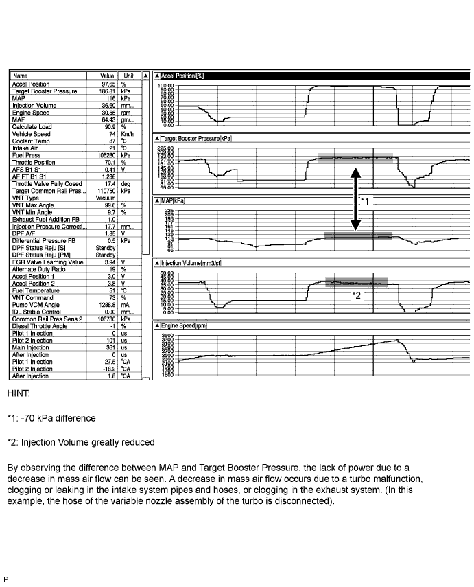
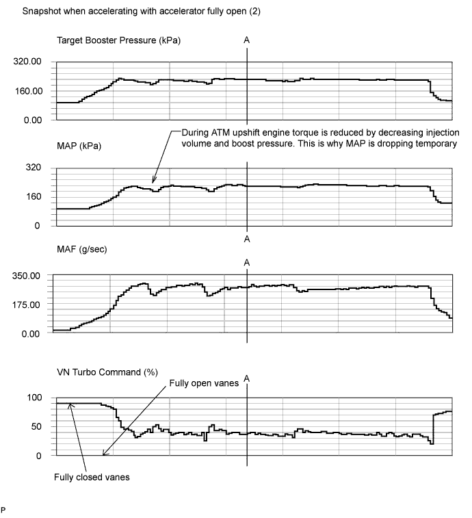
Lack of power caused by overly low boost pressure
-
Lack of power caused by overly low MAF
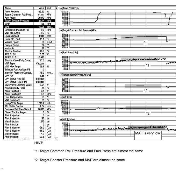
In this example, the MAF (Mass Air Flow) value decreases greatly due to foreign matter being stuck to the MAF sensor and causes a lack of power. The maximum fuel injection volume value is limited by the MAF value. As a result, there is a lack of power due to a lack of injection volume.
In this case, even when the accelerator is fully open, the calculated load is low. (Calculated Load = Injection Volume / Maximum Injection Volume at Current Engine Speed)
Basically the Manifold Absolute Pressure (MAP) is approximately equal to the Target Booster Pressure and this indicates that the turbo charger functions properly.
-
EGR valve stuck in open position
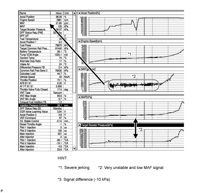
In this example, the EGR valve stuck in open position. Even with the accelerator pedal fully depressed, the EGR does not fully closed and the MAF signal is low.
Therefore, the fuel injection volume becomes limited and there is a lack of power. Jerking is also evident. At this time, even while accelerating with the accelerator fully open, the calculated load is low. (Calculated Load = Current Injection Volume / Maximum Injection Volume at Current Engine Speed)
Basically the Manifold Absolute Pressure (MAP) is approximately equal to the Target Booster Pressure and this indicates that the turbo charger functions properly.
-
INSPECTION PROCEDURE
-
Explanation of Symptom
Lack of Power The power of the diesel engine is determined by the quantity of injected fuel and the quantity of intake air.
The quantity of injected fuel is determined by the fuel pressure and the amount of time the injector is open for. Basically, the fuel pressure is controlled to reach the target fuel pressure. The throttle valve does not restrict air flow volume, so the manifold absolute pressure is almost the same as atmospheric pressure when idling. At more than approximately 1500 rpm, the turbo starts to operate causing the manifold absolute pressure to become higher than atmospheric pressure.
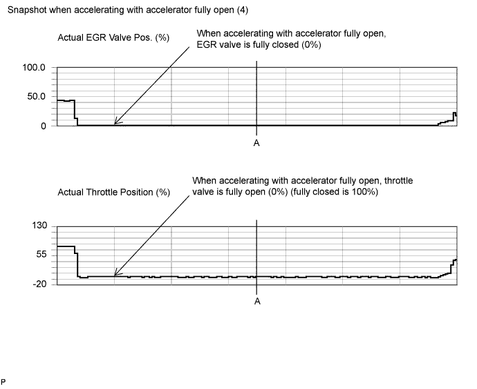
The manifold absolute pressure is controlled to reach the Target Booster Pressure. Also, When accelerating the vehicle at full throttle, the throttle is fully open and the EGR valve is fully closed, preserving the mass air flow.
-
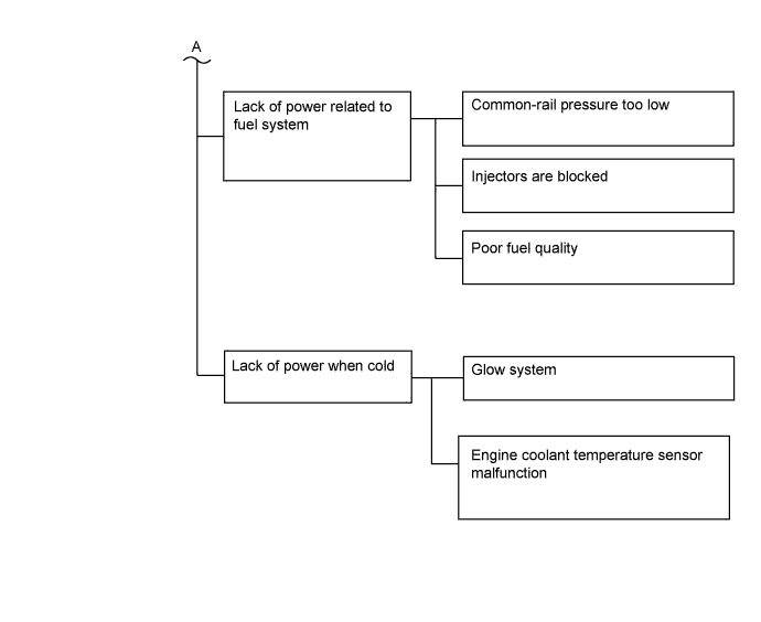
Trouble Area Chart According to Problem Cause
Note
-
After replacing the fuel supply pump, the ECM needs initialization Click here.
-
After replacing the fuel injector, the ECM needs registration Click here.
Tech Tips
-
Before troubleshooting, conduct the following:
-
Check the fuel quality.
-
Check the fuel for air.
-
Check the fuel system for blockages.
-
Check the air filter.
-
Check the engine oil.
-
Check the engine coolant.
-
Check the engine idling speed and the maximum engine speed.
-
PROCEDURE
-
READ OUTPUT DTC (RELATED TO ENGINE)
-
Connect the intelligent tester to the DLC3.
-
Turn the ignition switch to ON and turn the tester on.
-
Enter the following menus: Powertrain / Engine / DTC.
-
Read pending DTCs.
Result Result Proceed to No DTCs are output A Engine related DTCs are output B
B 
GO TO DTC CHART Click here
A 
-
-
READ VALUE USING INTELLIGENT TESTER
Tech Tips
This inspection is not necessary for A/T vehicles.
-
Connect the intelligent tester to the DLC3.
-
Turn the ignition switch to ON and turn the tester on.
-
Enter the following menus: Powertrain / Engine / Data List / Low Gear Switch.
-
Check the Data List when the shift lever is moved to 1 or any position other than 1.
OK Data List Shift Position Specified Condition Low Gear Switch 1 ON Low Gear Switch Not in 1 OFF
NG
REPLACE SHIFT POSITION SWITCH Click here
OK
-
-
TAKE DATA LIST DURING LACK OF POWER
-
Connect the intelligent tester to the DLC3.
-
Start the engine and turn the tester on.
-
Enter the following menus: Powertrain / Engine / Data List / All Data.
-
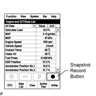
Take a snapshot of the following Data Lists with the intelligent tester during lack of power.
Tech Tips
-
A snapshot can be used to compare vehicle data from the time of the malfunction to normal data and is very useful for troubleshooting. The data in the illustration below is that of a normal vehicle, but as the data varies between individual vehicles, this data should only be used for reference.
-
Graphs like the ones shown below can be displayed by transferring the stored snapshot from the tester to a PC. Intelligent Viewer must be installed on the PC.
-
Move the shift lever to D and accelerate the vehicle with the accelerator fully open. (Obey all laws and regulations, and pay attention to driving conditions while driving the vehicle). Then, check the Data List with the engine warmed up and idling.
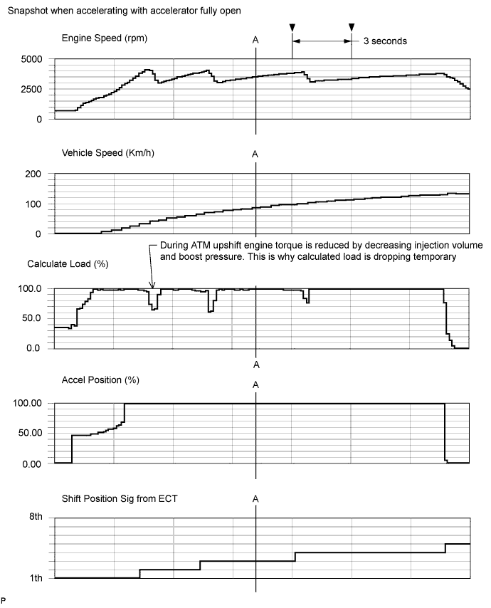
Reference Values with Engine Speed at 3500 rpm (Point A) Data List Value Unit Vehicle Speed 85 km/h Engine Speed 3500 rpm Accel Position 99.60 % Shift position SIG from ECT 3 th Target Booster Pressure 222.26 kPa MAP 224 kPa MAF 271.51 g/sec Calculate Load 99.6 % Target Common Rail Pressure 171150 kPa Fuel Press 171870 kPa Target Pump SCV Current 1594.6 mA Injection Volume 71.34 mm3/st
VN Turbo Command 38 % Actual EGR Valve Pos.
Actual EGR Valve Pos. #2
0 % Actual Throttle Position
Actual Throttle Position #2
0 % Data Condition Idling (Engine warmed up) Data List Value Unit Engine Speed 599 rpm Target Booster Pressure 99.23 kPa MAP 97 kPa MAF 8.39 g/sec Target Common Rail Pressure 32000 kPa Fuel Press 32100 kPa Injection Volume 6.13 mm3/st
VN Turbo Command 87 % Actual EGR Valve Pos.
Actual EGR Valve Pos. #2
43.5 % Actual Throttle Position
Actual Throttle Position #2
84 % Accel Position 0 % Injection Feedback Val #1 0.0 mm3/st
Injection Feedback Val #2 0.3 mm3/st
Injection Feedback Val #3 0.0 mm3/st
Injection Feedback Val #4 -0.4 mm3/st
Injection Feedback Val #5 -0.4 mm3/st
Injection Feedback Val #6 0.3 mm3/st
Injection Feedback Val #7 0.0 mm3/st
Injection Feedback Val #8 -0.5 mm3/st
Target EGR Pos.
Target EGR Pos. #2
43.5 % Atmosphere Pressure 99 kPa Coolant Temp 78 °C Tech Tips
Actual Examples of Malfunction (See "Diagnostic Help" menu)
-
Lack of power caused by overly low boost pressure
-
Lack of power caused by overly low MAF
-
EGR valve stuck in open position
-
NEXT
-
-
CHECK SNAPSHOT
-
Check the condition of the vehicle using the snapshot taken during the lack of power.
Result Result Proceed to Fuel Press is less than "Target Common Rail Pressure -20000 kPa" when accelerating with accelerator fully open A Target Pump SCV Current 3000 mA or more B One of the Injection Feedback Val #1 to 8 values is outside the range of +/-3 mm3/st when idling after warm up
C Injection Feedback Val #1 to #8 is within the range of +/-3 mm3/st and the Injection Volume is more than 10 mm3/st when idling after warm up
D None of the above conditions apply E
A 
BLEED AIR FROM FUEL SYSTEM Click here
B
REPLACE FUEL SUPPLY PUMP Click here
C
PERFORM ACTIVE TEST USING INTELLIGENT TESTER Click here
D
REPLACE FUEL INJECTORS OF ALL CYLINDER Click here
E
-
-
CHECK SNAPSHOT
-
Check the condition of the vehicle using the snapshot taken during the lack of power.
Result Result Proceed to MAP is less than "Target Booster Pressure -20 kPa" (MAF is normal) when accelerating with accelerator fully open A MAF is low when accelerating with accelerator fully open (MAP is normal)
-
3000 rpm: 150 g/sec or less
-
3500 rpm: 160 g/sec or less
-
4000 rpm: 160 g/sec or less
Tech Tips
-
If the MAF (Mass Air Flow) decreases, Calculate Load will be 80% or less when accelerating with the accelerator fully open.
-
During acceleration with the accelerator fully open, MAF (Mass Air Flow) is 40 g/sec or more less than the estimated MAF value* calculated based on MAP.
B MAP and MAF are both low when accelerating with the accelerator fully open C None of the above conditions apply D 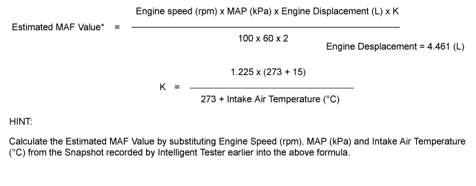
-
B
INSPECT MASS AIR FLOW METER Click here
C
READ VALUE USING INTELLIGENT TESTER Click here
D
CHECK TEMPERATURE WHEN LACK OF POWER OCCURS Click here
A
-
-
INSPECT VACUUM HOSE
-
Check the vacuum hose connection (manifold absolute pressure sensor).
OK Vacuum hose is connected securely.
NG
REPLACE VACUUM HOSE
OK
-
-
READ VALUE USING INTELLIGENT TESTER
-
Connect the intelligent tester to the DLC3.
-
Turn the ignition switch to ON and turn the tester on.
-
Enter the following menus: Powertrain / Engine / Data List / MAP and Atmosphere Pressure.
-
Compare MAP to Atmosphere Pressure when the ignition switch is ON (engine stopped).
Tech Tips
-
If MAP and Atmosphere Pressure have the same value, both are normal. If there is a difference of 10 kPa or more, compare the values to the atmospheric pressure for that day. The sensor whose deviation is the greatest is malfunctioning.
-
Standard atmospheric pressure is 101 kPa. For every 100 m increase in altitude, pressure drops by 1 kPa. Varies by weather (high atmospheric pressure, low atmospheric pressure).
Result Result Proceed to Atmosphere Pressure is different from actual atmospheric pressure A MAP is different from actual atmospheric pressure B MAP and Atmosphere Pressure have the same value C -
A
REPLACE ECM Click here
B
REPLACE MANIFOLD ABSOLUTE PRESSURE SENSOR Click here
C
READ VALUE USING INTELLIGENT TESTER Click here
-
-
INSPECT MASS AIR FLOW METER
-
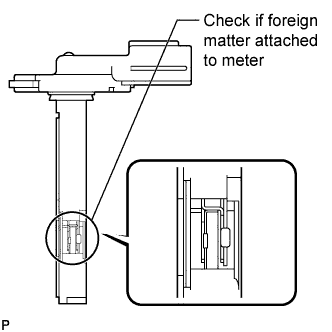
Using a work light, check that the platinum filament (heater portion) in the mass air flow meter has no foreign matter attached.
Standard No foreign matter attached. -
Connect the intelligent tester to the DLC3.
-
Turn the ignition switch to ON and turn the tester on.
-
Enter the following menus: Powertrain / Engine / Data List / MAF.
-
Read the value.
OK 2 g/sec or less.
NG
REPLACE MASS AIR FLOW METER Click here
OK
-
-
INSPECT EGR VALVE ASSEMBLY (No. 1 or No. 2)
Tech Tips
For vehicles without EGR valve, perform troubleshooting from the next step.
-
Check the EGR valve condition using the snapshot taken when accelerating with the accelerator fully open.
Standard Value Tester Display Standard Value Actual EGR Valve Pos. 0% Actual EGR Valve Pos. #2 0% -
Next, after the engine is warmed up, stop the engine and wait for 15 seconds. After that, start the engine again and idle it for 30 seconds. Then stop the engine and wait for 15 seconds. After starting the engine again, read the Data List values while idling.
Standard Value Tester Display Standard Value EGR Close Learn Val. 3.5 to 4.5 V EGR Close Lrn. Val. #2 3.5 to 4.5 V EGR Close Lrn. Status ON Result Result Suspected Trouble Area Proceed to A: Actual EGR Valve Pos with the ignition switch ON and the engine stopped is 0%. During idling, EGR valve is partially open. (Basically, it smoothly follows Target EGR Position). When A is not met: EGR valve is stuck B B: EGR Close Learn Val is within the standard value and EGR Close Lrn Status is ON. When B is not met: EGR valve does not close B Both A and B are OK - A Tech Tips
-
The 1VD engine has 2 EGR valves. Comparing the movements of the 2 valves can be a useful reference for diagnosing malfunctions. If 1 of the 2 valves becomes unable to close, the turbo will perform compensation control and a lack of power will not be felt but surging may be felt.
-
B
REPLACE EGR VALVE ASSEMBLY (No. 1 or No. 2) Click here
A
-
-
READ VALUE USING INTELLIGENT TESTER
-
Connect the intelligent tester to the DLC3.
-
Turn the ignition switch to ON and turn the tester on.
-
Enter the following menus: Powertrain / Engine / Data List / Accel Position.
-
Read the value.
Standard Value Condition Standard Value Accelerator pedal released 0% Accelerator pedal depressed 100% Accelerator pedal released → depressed
Tech Tips
Make sure the Accel Position opening angle moves smoothly.
0 to 100%
NG
REPLACE ACCELERATOR PEDAL ROD ASSEMBLY Click here
OK
-
-
READ VALUE USING INTELLIGENT TESTER
-
Connect the intelligent tester to the DLC3.
-
Turn the ignition switch to ON and turn the tester on.
-
Enter the following menus: Powertrain / Engine / Data List / Actual Throttle Position, Actual Throttle Position #2.
-
Read the value.
Standard Value Condition Standard Value Ignition switch ON -5 to 5 % Idling (warmed up engine) 0 to 90% Accelerator pedal fully depressed
Tech Tips
Make sure the Accel Position opening angle moves smoothly.
-5 to 5 % Tech Tips
-
Fully open: 0%
-
Fully close: 100%
-
The 1VD engine has 2 throttles. Diagnosis of malfunctions can be performed by comparing the movements of the 2 diesel throttles. If the Throttle Motor Duty of an operating diesel throttle is not within 50 +/-40%, the throttle is not sliding properly.
-
NG
REPLACE DIESEL THROTTLE BODY (for Bank 1 or Bank 2) Click here
OK
-
-
CHECK INTAKE SYSTEM
-
Check for air leakage and blockage between the air cleaner and turbocharger, and between the turbocharger and intake manifold.
Tech Tips
-
Check that the intercooler is not clogged with foreign matter.
-
Check that there are no disconnected, pinched or leaking hoses or pipes.
-
Check that there are no modifications made by the user.
OK No leakage or blockage. -
NG
REPAIR OR REPLACE MALFUNCTIONING PARTS
OK
-
-
CHECK TURBOCHARGER SUB-ASSEMBLY (MECHANICAL PROBLEM (for Bank 1 or Bank 2))
-
Disconnect the air cleaner hose.
-
Use a mirror to visually check the turbocharger for any mechanical problems.
-
When the engine is cold, check that the impeller of the turbocharger rotates smoothly, and confirm whether there is any damage to it.
OK Impeller rotates smoothly and is not damaged. -
Reconnect the air cleaner hose.
NG
REPLACE TURBOCHARGER SUB-ASSEMBLY (for Bank 1 or Bank 2) Click here
OK
-
-
INSPECT TURBOCHARGER SUB-ASSEMBLY (for Bank 1 or Bank 2)
-
Check the motor movement when turning the ignition switch to ON, when starting the engine and then when turning the ignition switch off.
OK Motor moves as shown in the illustration. 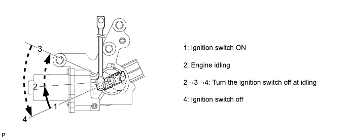
NG
REPLACE TURBOCHARGER SUB-ASSEMBLY (for Bank 1 or Bank 2) Click here
OK
-
-
CHECK MONOLITHIC CONVERTER ASSEMBLY (for Bank 1 or Bank 2)
-
Check that there are no clogs, dents, etc. in the monolithic converter assembly.
OK No clogs, dents, etc.
NG
REPLACE MONOLITHIC CONVERTER ASSEMBLY (for Bank 1 or Bank 2)
OK
-
-
CONFIRM WHETHER MALFUNCTION HAS BEEN SUCCESSFULLY REPAIRED
-
Check whether the lack of power has been successfully repaired.
OK Malfunction has been repaired successfully. Tech Tips
Symptoms may have appeared due to carbon deposits, etc.
NG
CHECK INTAKE SYSTEM DEPOSIT Click here
OK 
END
-
-
BLEED AIR FROM FUEL SYSTEM
-

Using the hand pump as indicated by the arrow in the illustration, bleed the fuel system. Continue pumping until pumping becomes difficult.
Tech Tips
When the fuel pressure during cranking is extremely low (1000 kPa or less), it is possible that fuel is not being supplied to the supply pump.
NEXT
-
-
CHECK IF FUEL IS BEING SUPPLIED TO FUEL SUPPLY PUMP
-
Disconnect the inlet hose from the fuel supply pump.
-
Operate the priming pump and check that fuel is being supplied to the fuel supply pump.
OK Fuel is properly supplied to the fuel supply pump when the priming pump is operated. Tech Tips
-
When lack on fuel, fuel pressure drops.
-
Inspect for fuel filter clogging.
(Check that the fuel filter is not clogged)
-
NG
CHECK AND REPLACE CLOGGED FUEL PIPE (INCLUDING FUEL FREEZING) (FUEL TANK - FUEL SUPPLY PUMP)
OK
-
-
CONFIRM WHETHER MALFUNCTION HAS BEEN SUCCESSFULLY REPAIRED
-
Check whether the lack of power has been successfully repaired.
Tech Tips
The Fuel Press is within +/-5000 kPa of Target Common Rail Pressure.
OK Malfunction has been repaired successfully.
OK
END
-
-
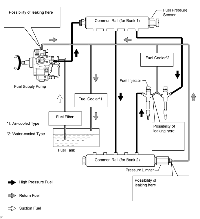
CHECK FUEL LEAK (FUEL SUPPLY PUMP)
-
Connect the intelligent tester to the DLC3.
-
Turn the ignition switch to ON and turn the tester on.
-
Enter the following menus: Powertrain / Engine / Data List / Fuel Press.
-
Pinch the fuel supply pump return hose and check that Fuel Press during cranking increases.
Result Result Proceed to No change A Fuel Press increases B
B
REPLACE FUEL SUPPLY PUMP Click here
A
-
-
CHECK FUEL LEAK (PRESSURE LIMITER) (COMMON RAIL (for Bank 2))
-
Connect the intelligent tester to the DLC3.
-
Turn the ignition switch to ON and turn the tester on.
-
Enter the following menus: Powertrain / Engine / Data List / Fuel Press.
-
Pinch the pressure limiter return hose and check that Fuel Press during cranking increases.
Result Result Proceed to No change A Fuel Press increases B
B
REPLACE COMMON RAIL (for Bank 2) Click here
A
-
-
REPLACE FUEL SUPPLY PUMP
-
Replace the fuel supply pump Click here.
NEXT
-
-
CONFIRM WHETHER MALFUNCTION HAS BEEN SUCCESSFULLY REPAIRED
-
Check whether the lack of power has been successfully repaired.
Tech Tips
The Fuel Press is within +/-5000 kPa of Target Common Rail Pressure.
NEXT
END
-
-
CHECK TEMPERATURE WHEN LACK OF POWER OCCURS
-
Check the temperature when lack of power occurs.
Result Result Proceed to Poor acceleration only when engine is cold A Poor acceleration when engine is cold and warm B
B
INSPECT INJECTOR COMPENSATION CODE Click here
A
-
-
INSPECT ENGINE COOLANT TEMPERATURE SENSOR
-
Inspect the engine coolant temperature sensor Click here.
Tech Tips
After warming up the engine, the engine coolant temperature should be 70°C (158°F) or more. After leaving the vehicle overnight, the engine coolant temperature should be nearly equal to the intake air temperature.
NG
REPLACE ENGINE COOLANT TEMPERATURE SENSOR Click here
OK
-
-
INSPECT GLOW PLUG ASSEMBLY (RESISTANCE)
-
Disconnect the glow plug connector.
-
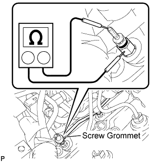
Measure the resistance according to the value(s) in the table below.
Standard Resistance Tester Connection Condition Specified Condition Glow plug terminal - Body ground 20°C (68°F) Approximately 1 Ω Tech Tips
If any of the glow plugs has an open circuit, the engine power will be insufficient only when the engine is cold.
Note
-
Exercise extreme care not to damage the glow plug pipes. Damaging them could cause an open circuit, or shorten the life of the glow plugs,
-
Keep the glow plugs free of oil and fuel while cleaning.
-
Wipe any oil off of the terminal and Bakelite washer with a clean, dry cloth during inspection.
-
Do not apply more than 11 V to the glow plugs as it may cause an open circuit.
-
NG
REPLACE GLOW PLUG ASSEMBLY Click here
OK
-
-
INSPECT INJECTOR COMPENSATION CODE
-
Read the injector compensation code Click here.
OK Compensation codes stored in the ECM match compensation codes of the installed fuel injectors.
NG
PERFORM REGISTRATION FUEL INJECTOR COMPENSATION CODE Click here
OK
-
-
CHECK FUEL QUALITY
-
Check that fuel with a low cetane number is used.
NEXT
-
-
CONFIRM WHETHER MALFUNCTION HAS BEEN SUCCESSFULLY REPAIRED
-
Check whether the lack of power has been successfully repaired by starting the engine.
NEXT
END
-
-
PERFORM ACTIVE TEST USING INTELLIGENT TESTER
Tech Tips
Use this Active Test to determine the malfunctioning cylinder.
-
Connect the intelligent tester to the DLC3.
-
Start the engine and turn the tester on.
-
Enter the following menus: Powertrain / Engine / Active Test / Control the Cylinder #1 to #8 Fuel Cut.
Tech Tips
-
If the engine idle speed does not change when a fuel injector is disabled, the cylinder being tested is malfunctioning.
-
If the cylinder being tested is normal, there will be a significant change in idle speed when the fuel injection is stopped for that cylinder.
-
NEXT
-
-
PERFORM ACTIVE TEST USING INTELLIGENT TESTER
Tech Tips
Use this Active Test to help determine whether a cylinder has compression loss or not.
-
Connect the intelligent tester to the DLC3.
-
Turn the ignition switch to ON and turn the tester on.
-
Enter the following menus: Powertrain / Engine / Active Test / Check the Cylinder Compression / Data List / Compression / Engine Speed of Cyl #1 to #8.
-
Check the engine speed during the Active Test.
OK If the values of Engine Speed Cyl #1 to #8 are within +/-10 rpm of each other. Tech Tips
When cranking, if the speed of a cylinder is approximately 100 rpm more than the other cylinders, there is probably a loss of compression in that cylinder.
OK
REPLACE FUEL INJECTOR OF MALFUNCTIONING CYLINDER Click here
NG
CHECK CYLINDER COMPRESSION PRESSURE OF MALFUNCTIONING CYLINDER Click here
-
-
CHECK CYLINDER COMPRESSION PRESSURE OF MALFUNCTIONING CYLINDER
Tech Tips
Measure the compression of the cylinder that had a high speed during the Active Test "Check the Cylinder Compression".
-
Check the cylinder compression pressure Click here.
NG
CHECK ENGINE TO DETERMINE CAUSE OF LOW COMPRESSION
OK
-
-
REPLACE FUEL INJECTOR OF MALFUNCTIONING CYLINDER
Tech Tips
The injector is determined to be faulty as the corresponding cylinder is malfunctioning, but has no compression loss.
NEXT
END
-
CHECK INTAKE SYSTEM DEPOSIT
-
Check if 3 mm or more of carbon is accumulating on the intake manifold, cylinder head, etc. and if so, clean it off.
NEXT
-
-
CONFIRM WHETHER MALFUNCTION HAS BEEN SUCCESSFULLY REPAIRED
Tech Tips
Symptoms may have appeared due to carbon deposits, etc.
NEXT
END