ECD SYSTEM (w/o DPF) Black Smoke Emitted
INSPECTION PROCEDURE
Note
-
After replacing the ECM, the new ECM needs registration Click here and initialization Click here.
-
After replacing a fuel supply pump, the ECM needs initialization Click here.
-
After replacing a fuel injector, the ECM needs registration Click here.
Tech Tips
Specified values in the following troubleshooting flowchart are for reference only. Variations in the Data List values may occur depending on the measuring conditions or the vehicle age. Do not assume the vehicle to be normal when the Data List outputs standard values. There may be concealed factors of the malfunction.
PROCEDURE
-
READ OUTPUT DTC (RELATED TO ENGINE)
-
Connect the intelligent tester to the DLC3.
-
Turn the ignition switch to ON and turn the tester on.
-
Enter the following menus: Powertrain / Engine / DTC.
-
Read the DTCs.
Result Result Proceed to No DTC is output A DTCs related to the engine are output B
B 
REPAIR OR REPLACE ENGINE CONTROL SYSTEM ACCORDING TO DTC OUTPUT Click here
A 
-
-
READ VALUE USING INTELLIGENT TESTER (INJECTION VOLUME AND INJECTION FEEDBACK VAL #1 TO #8)
-
Connect the intelligent tester to the DLC3.
-
Start the engine and turn the tester on.
-
Enter the following menus: Powertrain / Engine / Data List.
-
Select the following menu items in order and read the values.
-
Injection Volume
-
Injection Feedback Val #1, #2, #3, #4, #5, #6, #7 and #8
Standard Value Item Engine Speed* Reference Value Injection Volume Idling (No engine load) 3.0 to 10 mm3/st
Injection Feedback Val #1 to #8 Idling (No engine load) -3.0 to 3.0 mm3/st
Tech Tips
*: If no idling conditions are specified, the shift lever should be in N, and the A/C switch and all accessory switches should be off.
-
NG 
READ VALUE USING INTELLIGENT TESTER (COOLANT TEMP) Click here
OK
-
-
PERFORM ENGINE SPEED ACCELERATION
Tech Tips
If the exhaust gas contains excessive black smoke, perform the following operations.
-
Accelerate the engine to the maximum speed with no load 20 times.
-
Check the volume of black smoke in the exhaust gas.
Result Result Proceed to Black smoke is not present OK Black smoke remains in the exhaust gas NG Tech Tips
Soot deposits in the exhaust system may cause excessive black smoke.
NG
CHECK INTAKE AIR CONTROL SYSTEM AND EXHAUST SYSTEM Click here
OK 
END
-
-
CHECK INTAKE AIR CONTROL SYSTEM AND EXHAUST SYSTEM
-
Inspect the engine condition Click here.
NG
REPAIR OR REPLACE LOCATIONS WHERE MALFUNCTIONS EXIST
OK
-
-
INSPECT MASS AIR FLOW METER
-
Inspect the mass air flow meter Click here.
NG
REPLACE MASS AIR FLOW METER Click here
OK
-
-
CHECK TURBOCHARGING PRESSURE
-
Check the turbocharging pressure Click here.
OK The turbocharger pressure is within the standard range.
NG
REPLACE TURBOCHARGER SUB-ASSEMBLY (for Bank 1 or Bank 2) Click here
OK
-
-
READ VALUE USING INTELLIGENT TESTER (DATA LIST)
-
Connect the intelligent tester to the DLC3.
-
Start the engine and turn the tester on.
-
Enter the following menus: Powertrain / Engine / Data List.
-
Select the following menu items in order and read the values.
-
Fuel Press
-
Injection Volume
-
Main Injection Period
-
Pilot 2 Injection Period
-
Injection Feedback Val #1, #2, #3, #4, #5, #6, #7 and #8
Reference Item Engine Speed* Reference Value Fuel Press Idling 27 to 37 MPa Fuel Press 2000 rpm (no engine load) 50 to 70 MPa Fuel Press 3000 rpm (no engine load) 52 to 76 MPa Injection Volume Idling 3.0 to 10 mm3/st
Injection Volume 2000 rpm (no engine load) 3.5 to 11 mm3/st
Injection Volume 3000 rpm (no engine load) 6.5 to 13 mm3/st
Main Injection Period Idling 430 to 730 μs Pilot 2 Injection Period Idling 390 to 490 μs Injection Feedback Val #1 to #8 Idling -3.0 to 3.0 mm3
Tech Tips
*: If no idling conditions are specified, the shift lever should be in N, and the A/C switch and all accessory switches should be off.
Result Result Proceed to Within reference value A One of Injection Feedback Val #1 to #8 is not within reference value B Other result C -
B
REPLACE MALFUNCTIONING FUEL INJECTOR Click here
C
READ VALUE USING INTELLIGENT TESTER (COOLANT TEMP) Click here
A
-
-
CHECK CYLINDER COMPRESSION PRESSURE
-
Check the cylinder compression pressure Click here.
NG
CHECK ENGINE TO DETERMINE CAUSE OF LOW COMPRESSION
OK
-
-
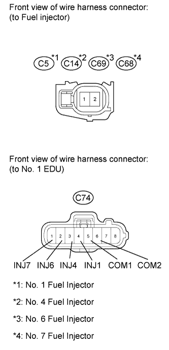
CHECK HARNESS AND CONNECTOR (FUEL INJECTOR - EDU)
-
Disconnect the fuel injector connectors.
-
Disconnect the No. 1 EDU connector.
-
Measure the resistance according to the value(s) in the table below.
Standard Resistance (Check for Open) No. 1 Tester Connection Condition Specified Condition C5-2 - C74-4 (INJ1) Always Below 1 Ω C14-2 - C74-3 (INJ4) Always Below 1 Ω C69-2 - C74-2 (INJ6) Always Below 1 Ω C68-2 - C74-1 (INJ7) Always Below 1 Ω C5-1 - C74-5 (COM1) Always Below 1 Ω C14-1 - C74-5 (COM1) Always Below 1 Ω C69-1 - C74-6 (COM2) Always Below 1 Ω C68-1 - C74-6 (COM2) Always Below 1 Ω Standard Resistance (Check for Short) No. 1 Tester Connection Condition Specified Condition C5-2 or C74-4 (INJ1) - Body ground Always 10 kΩ or higher C14-2 or C74-3 (INJ4) - Body ground Always 10 kΩ or higher C69-2 or C74-2 (INJ6) - Body ground Always 10 kΩ or higher C68-2 or C74-1 (INJ7) - Body ground Always 10 kΩ or higher C5-1 or C74-5 (COM1) - Body ground Always 10 kΩ or higher C14-1 or C74-5 (COM1) - Body ground Always 10 kΩ or higher C69-1 or C74-6 (COM2) - Body ground Always 10 kΩ or higher C68-1 or C74-6 (COM2) - Body ground Always 10 kΩ or higher -
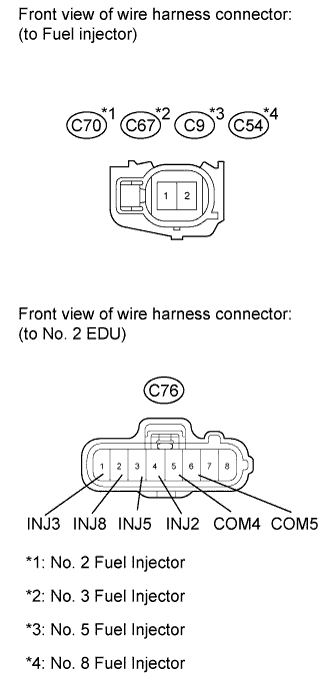
Disconnect the fuel injector connectors.
-
Disconnect the No. 2 EDU connector.
-
Measure the resistance according to the value(s) in the table below.
Standard Resistance (Check for Open) No. 2 Tester Connection Condition Specified Condition C70-2 - C76-4 (INJ2) Always Below 1 Ω C9-2 - C76-3 (INJ5) Always Below 1 Ω C67-2 - C76-1 (INJ3) Always Below 1 Ω C54-2 - C76-2 (INJ8) Always Below 1 Ω C70-1 - C76-5 (COM4) Always Below 1 Ω C9-1 - C76-5 (COM4) Always Below 1 Ω C67-1 - C76-6 (COM5) Always Below 1 Ω C54-1 - C76-6 (COM5) Always Below 1 Ω Standard Resistance (Check for Short) No. 2 Tester Connection Condition Specified Condition C70-2 or C76-4 (INJ2) - Body ground Always 10 kΩ or higher C9-2 or C76-3 (INJ5) - Body ground Always 10 kΩ or higher C67-2 or C76-1 (INJ3) - Body ground Always 10 kΩ or higher C54-2 or C76-2 (INJ8) - Body ground Always 10 kΩ or higher C70-1 or C76-5 (COM4) - Body ground Always 10 kΩ or higher C9-1 or C76-5 (COM4) - Body ground Always 10 kΩ or higher C67-1 or C76-6 (COM5) - Body ground Always 10 kΩ or higher C54-1 or C76-6 (COM5) - Body ground Always 10 kΩ or higher
NG
REPAIR OR REPLACE HARNESS OR CONNECTOR
OK
-
-
PERFORM ACTIVE TEST USING INTELLIGENT TESTER (CONTROL THE CYLINDER FUEL CUT)
-
Connect the intelligent tester to the DLC3.
-
Start the engine and turn the tester on.
-
Enter the following menus: Powertrain / Engine / Active Test / Control the Cylinder #1, #2, #3, #4, #5, #6, #7 and #8 Fuel Cut.
-
Check the engine idling condition while the fuel injection of each cylinder is cut using the tester.
Result Engine Idling Condition Proceed to Becomes unstable A Does not change B Tech Tips
Replace the fuel injector mounted on the cylinder that causes no significant idle speed change.
B
REPLACE MALFUNCTIONING FUEL INJECTOR Click here
A
REPLACE INJECTOR DRIVER (No. 1 and/or No. 2) Click here
-
-
READ VALUE USING INTELLIGENT TESTER (COOLANT TEMP)
-
Connect the intelligent tester to the DLC3.
-
Turn the ignition switch to ON and turn the tester on.
-
Start the engine and warm it up.
-
Enter the following menus: Powertrain / Engine / Data List / Coolant Temp.
-
Read the value.
Standard Value Item Inspection Condition Reference Value Coolant Temp Idling with warm engine (A/C switch off) 75 to 90°C (167 to 194°F)
NG
INSPECT ENGINE COOLANT TEMPERATURE SENSOR Click here
OK
-
-
READ VALUE USING INTELLIGENT TESTER (MAP)
-
Connect the intelligent tester to the DLC3.
-
Turn the ignition switch to ON and turn the tester on.
-
Start the engine and warm it up.
-
Enter the following menus: Powertrain / Engine / Data List / MAP.
-
Read the value.
OK Same value as the actual atmospheric pressure.
NG
CHECK HARNESS AND CONNECTOR (MANIFOLD ABSOLUTE PRESSURE SENSOR - ECM) Click here
OK
-
-
READ VALUE USING INTELLIGENT TESTER (ENGINE SPEED)
-
Connect the intelligent tester to the DLC3.
-
Turn the ignition switch to ON and turn the tester on.
-
Enter the following menus: Powertrain / Engine / Data List / Engine Speed.
-
Read the value.
Standard Value Item Inspection Condition Reference Value Engine Speed Idling with warm engine (A/C switch off)
-
500 to 600 rpm (M/T)
-
550 to 650 rpm (A/T)
-
NG
INSPECT CRANKSHAFT POSITION SENSOR Click here
OK
-
-
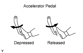
READ VALUE USING INTELLIGENT TESTER (ACCEL SENS. NO.# VOLT %)
-
Connect the intelligent tester to the DLC3.
-
Turn the ignition switch to ON and turn the tester on.
-
Enter the following menus: Powertrain / Engine / Data List / Accel Sens. No.1 Volt % and Accel Sens. No.2 Volt %.
-
Read the values.
Standard Accelerator Pedal Accel Sens. No.1 Volt % Accel Sens. No.2 Volt % Released 10 to 22% 24 to 40% Depressed 52 to 90% 68 to 99%
NG
CHECK HARNESS AND CONNECTOR (ACCELERATOR PEDAL POSITION SENSOR - ECM) Click here
OK
-
-
READ VALUE USING INTELLIGENT TESTER (INTAKE AIR)
-
Connect the intelligent tester to the DLC3.
-
Turn the ignition switch to ON and turn the tester on.
-
Enter the following menus: Powertrain / Engine / Data List / Inlet Air.
-
Read the value.
OK Same as air temperature near intake manifold.
NG
INSPECT INTAKE AIR TEMPERATURE SENSOR Click here
OK
-
-
READ VALUE USING INTELLIGENT TESTER (FUEL PRESS)
-
Connect the intelligent tester to the DLC3.
-
Turn the ignition switch to ON and turn the tester on.
-
Start the engine and warm it up.
-
Enter the following menus: Powertrain / Engine / Data List / Fuel Press.
-
Read the value.
Standard Value Item Inspection Condition Reference Value Fuel Press Idling 27 to 37 MPa
NG
INSPECT COMMON RAIL (for Bank 1) (FUEL PRESSURE SENSOR) Click here
OK
REPLACE ECM Click here
-
-
INSPECT ENGINE COOLANT TEMPERATURE SENSOR
-
Inspect the engine coolant temperature sensor Click here.
NG
REPLACE ENGINE COOLANT TEMPERATURE SENSOR Click here
OK
REPAIR OR REPLACE HARNESS OR CONNECTOR
-
-
CHECK HARNESS AND CONNECTOR (MANIFOLD ABSOLUTE PRESSURE SENSOR - ECM)
-
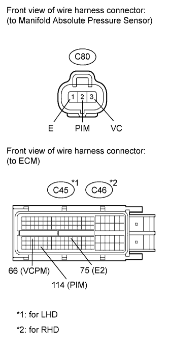
Disconnect the manifold absolute pressure sensor connector.
-
Disconnect the ECM connector.
-
Measure the resistance according to the value(s) in the table below.
Standard Resistance (Check for Open) for LHD Tester Connection Condition Specified Condition C80-2 (PIM) - C45-114 (PIM) Always Below 1 Ω C80-3 (VC) - C45-66 (VCPM) Always Below 1 Ω C80-1 (E) - C45-75 (E2) Always Below 1 Ω for RHD Tester Connection Condition Specified Condition C80-2 (PIM) - C46-114 (PIM) Always Below 1 Ω C80-3 (VC) - C46-66 (VCPM) Always Below 1 Ω C80-1 (E) - C46-75 (E2) Always Below 1 Ω Standard Resistance (Check for Short) for LHD Tester Connection Condition Specified Condition C80-2 (PIM) or C45-114 (PIM) - Body ground Always 10 kΩ or higher C80-3 (VC) or C45-66 (VCPM) - Body ground Always 10 kΩ or higher C80-1 (E) or C45-75 (E2) - Body ground Always 10 kΩ or higher for RHD Tester Connection Condition Specified Condition C80-2 (PIM) or C46-114 (PIM) - Body ground Always 10 kΩ or higher C80-3 (VC) or C46-66 (VCPM) - Body ground Always 10 kΩ or higher C80-1 (E) or C46-75 (E2) - Body ground Always 10 kΩ or higher
NG
REPAIR OR REPLACE HARNESS OR CONNECTOR
OK
REPLACE MANIFOLD ABSOLUTE PRESSURE SENSOR Click here
-
-
INSPECT CRANKSHAFT POSITION SENSOR
-
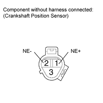
Disconnect the crankshaft position sensor connector.
-
Measure the resistance according to the value(s) in the table below.
Standard Resistance Tester Connection Condition Specified Condition 1 (NE+) - 2 (NE-) Cold 1630 to 2740 Ω 1 (NE+) - 2 (NE-) Hot 2065 to 3225 Ω Tech Tips
In the table above, the terms "Cold" and "Hot" refer to the temperature of the coils in the sensor. "Cold" means approximately -10 to 50°C (14 to 122°F). "Hot" means approximately 50 to 100°C (122 to 212°F).
NG
REPLACE CRANKSHAFT POSITION SENSOR Click here
OK
REPAIR OR REPLACE HARNESS OR CONNECTOR
-
-
CHECK HARNESS AND CONNECTOR (ACCELERATOR PEDAL POSITION SENSOR - ECM)
-
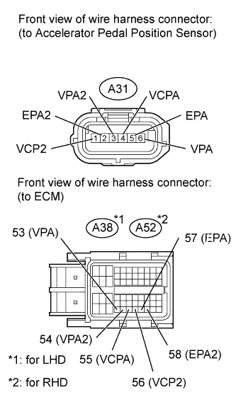
Disconnect the accelerator pedal position sensor connector.
-
Disconnect the ECM connector.
-
Measure the resistance according to the value(s) in the table below.
Standard Resistance (Check for Open) for LHD Tester Connection Condition Specified Condition A31-1 (VCP2) - A38-56 (VCP2) Always Below 1 Ω A31-2 (EPA2) - A38-58 (EPA2) Always Below 1 Ω A31-3 (VPA2) - A38-54 (VPA2) Always Below 1 Ω A31-4 (VCPA) - A38-55 (VCPA) Always Below 1 Ω A31-5 (EPA) - A38-57 (EPA) Always Below 1 Ω A31-6 (VPA) - A38-53 (VPA) Always Below 1 Ω for RHD Tester Connection Condition Specified Condition A31-1 (VCP2) - A52-56 (VCP2) Always Below 1 Ω A31-2 (EPA2) - A52-58 (EPA2) Always Below 1 Ω A31-3 (VPA2) - A52-54 (VPA2) Always Below 1 Ω A31-4 (VCPA) - A52-55 (VCPA) Always Below 1 Ω A31-5 (EPA) - A52-57 (EPA) Always Below 1 Ω A31-6 (VPA) - A52-53 (VPA) Always Below 1 Ω Standard Resistance (Check for Short) for LHD Tester Connection Condition Specified Condition A31-1 (VCP2) or A38-56 (VCP2) - Body ground Always 10 kΩ or higher A31-2 (EPA2) or A38-58 (EPA2) - Body ground Always 10 kΩ or higher A31-3 (VPA2) or A38-54 (VPA2) - Body ground Always 10 kΩ or higher A31-4 (VCPA) or A38-55 (VCPA) - Body ground Always 10 kΩ or higher A31-5 (EPA) or A38-57 (EPA) - Body ground Always 10 kΩ or higher A31-6 (VPA) or A38-53 (VPA) - Body ground Always 10 kΩ or higher for RHD Tester Connection Condition Specified Condition A31-1 (VCP2) or A52-56 (VCP2) - Body ground Always 10 kΩ or higher A31-2 (EPA2) or A52-58 (EPA2) - Body ground Always 10 kΩ or higher A31-3 (VPA2) or A52-54 (VPA2) - Body ground Always 10 kΩ or higher A31-4 (VCPA) or A52-55 (VCPA) - Body ground Always 10 kΩ or higher A31-5 (EPA) or A52-57 (EPA) - Body ground Always 10 kΩ or higher A31-6 (VPA) or A52-53 (VPA) - Body ground Always 10 kΩ or higher
NG
REPAIR OR REPLACE HARNESS OR CONNECTOR
OK
REPLACE ACCELERATOR PEDAL ROD ASSEMBLY (ACCELERATOR PEDAL POSITION SENSOR) Click here
-
-
INSPECT INTAKE AIR TEMPERATURE SENSOR
-
Remove the mass air flow meter Click here.
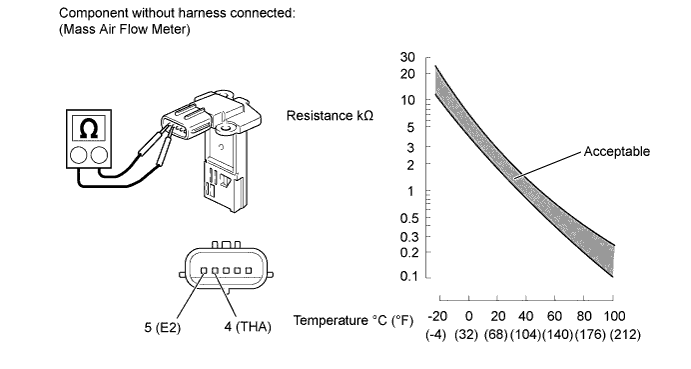
-
Measure the resistance according to the value(s) in the table below.
Standard Resistance Tester Connection Condition Specified Condition 4 (THA) - 5 (E2) -20°C (-4°F) 13.6 to 18.4 kΩ 20°C (68°F) 2.21 to 2.69 kΩ 60°C (140°F) 0.49 to 0.67 kΩ
NG
REPLACE MASS AIR FLOW METER Click here
OK
REPAIR OR REPLACE HARNESS OR CONNECTOR
-
-
INSPECT COMMON RAIL (for Bank 1) (FUEL PRESSURE SENSOR)
-
Inspect the fuel pressure sensor Click here.
NG
REPLACE COMMON RAIL (for Bank 1) Click here
OK
-
-
CHECK HARNESS AND CONNECTOR (FUEL PRESSURE SENSOR - ECM)
-
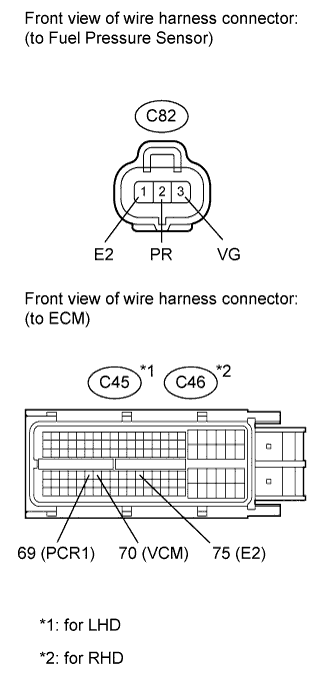
Disconnect the fuel pressure sensor connector.
-
Disconnect the ECM connector.
-
Measure the resistance according to the value(s) in the table below.
Standard Resistance (Check for Open) for LHD Tester Connection Condition Specified Condition C82-2 (PR) - C45-69 (PCR1) Always Below 1 Ω C82-3 (VG) - C45-70 (VCM) Always Below 1 Ω C82-1 (E2) - C45-75 (E2) Always Below 1 Ω for RHD Tester Connection Condition Specified Condition C82-2 (PR) - C46-69 (PCR1) Always Below 1 Ω C82-3 (VG) - C46-70 (VCM) Always Below 1 Ω C82-1 (E2) - C46-75 (E2) Always Below 1 Ω Standard Resistance (Check for Short) for LHD Tester Connection Condition Specified Condition C82-2 (PR) or C45-69 (PCR1) - Body ground Always 10 kΩ or higher C82-3 (VG) or C45-70 (VCM) - Body ground Always 10 kΩ or higher C82-1 (E2) or C45-75 (E2) - Body ground Always 10 kΩ or higher for RHD Tester Connection Condition Specified Condition C82-2 (PR) or C46-69 (PCR1) - Body ground Always 10 kΩ or higher C82-3 (VG) or C46-70 (VCM) - Body ground Always 10 kΩ or higher C82-1 (E2) or C46-75 (E2) - Body ground Always 10 kΩ or higher
NG
REPAIR OR REPLACE HARNESS OR CONNECTOR
OK
-
-
REPLACE ECM
-
Replace the ECM Click here.
Note
After replacing the ECM, the new ECM needs registration Click here and initialization Click here.
-
Check if the engine starts smoothly or if the engine stalls.
OK The engine starts smoothly and does not stall.
NG
REPLACE FUEL SUPPLY PUMP Click here
OK
END
-