ECD SYSTEM (w/ DPF) ECM Power Source Circuit
DESCRIPTION
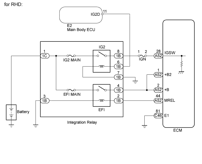
When the engine switch is turned on (IG), the battery voltage is applied to the IGSW terminal of the ECM. The output signal from the MREL terminal of the ECM causes current to flow to the coil, closing the contacts of the integration relay (EFI relay) and supplying power to terminal +B of the ECM.
WIRING DIAGRAM

INSPECTION PROCEDURE
Note
After replacing the ECM, the new ECM needs registration Click here and initialization Click here.
PROCEDURE
-
INSPECT INTEGRATION RELAY (INTEGRATION RELAY - BODY GROUND)
-
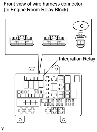
Remove the integration relay from the engine room relay block.
-
Measure the voltage according to the value(s) in the table below.
Standard Voltage Tester Connection Condition Specified Condition 1C-1 - Body ground Always 11 to 14 V
NG 
REPAIR OR REPLACE HARNESS OR CONNECTOR
OK 
-
-
INSPECT INTEGRATION RELAY (EFI RELAY AND IG2 RELAY)
-
Remove the integration relay from the engine room relay block.
-
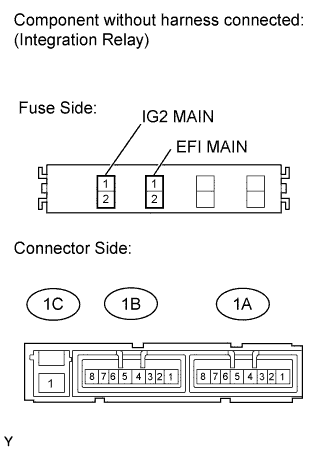
Inspect the EFI MAIN fuse and the IG2 MAIN fuse.
-
Remove the EFI MAIN fuse and IG2 MAIN fuse from the integration relay.
-
Measure the resistance according to the value(s) in the table below.
Standard Resistance Tester Connection Condition Specified Condition EFI MAIN fuse Always Below 1 Ω IG2 MAIN fuse Always Below 1 Ω
-
-
Inspect the EFI relay and the IG2 relay.
-
Measure the resistance according to the value(s) in the table below.
Standard Resistance Tester Connection Condition Specified Condition 1C-1 - 1B-4 Battery voltage not applied to terminals 1B-2 and 1B-3 10 kΩ or higher Battery voltage applied to terminals 1B-2 and 1B-3 Below 1 Ω 1C-1 - 1B-8 Battery voltage not applied to terminals 1B-7 and 1B-6 10 kΩ or higher Battery voltage applied to terminals 1B-7 and 1B-6 Below 1 Ω
-
NG
REPLACE INTEGRATION RELAY
OK
-
-
CHECK HARNESS AND CONNECTOR (+B AND MREL CIRCUIT)
-
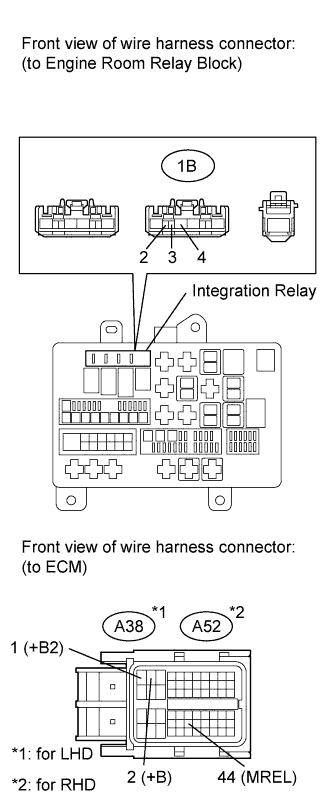
Check the harness and the connectors between the integration relay and the ECM.
-
Remove the integration relay from the engine room relay block.
-
Disconnect the ECM connector.
-
Measure the resistance according to the value(s) in the table below.
Standard Resistance for LHD Tester Connection Condition Specified Condition A38-44 (MREL) - 1B-2 Always Below 1 Ω A38-2 (+B) - 1B-4 Always Below 1 Ω A38-1 (+B2) - 1B-4 Always Below 1 Ω A38-44 (MREL) or 1B-2 - Body ground Always 10 kΩ or higher A38-2 (+B) or 1B-4 - Body ground Always 10 kΩ or higher A38-1 (+B2) or 1B-4 - Body ground Always 10 kΩ or higher for RHD Tester Connection Condition Specified Condition A52-44 (MREL) - 1B-2 Always Below 1 Ω A52-2 (+B) - 1B-4 Always Below 1 Ω A52-1 (+B2) - 1B-4 Always Below 1 Ω A52-44 (MREL) or 1B-2 - Body ground Always 10 kΩ or higher A52-2 (+B) or 1B-4 - Body ground Always 10 kΩ or higher A52-1 (+B2) or 1B-4 - Body ground Always 10 kΩ or higher
-
-
Check the harness and connectors between the integration relay and body ground.
-
Measure the resistance according to the value(s) in the table below.
Standard Resistance Tester Connection Condition Specified Condition 1B-3 - Body ground Always Below 1 Ω
-
NG
REPAIR OR REPLACE HARNESS OR CONNECTOR
OK
-
-
CHECK HARNESS AND CONNECTOR (ECM - BODY GROUND)
-
Disconnect the ECM connector.
-
Measure the resistance according to the value(s) in the table below.
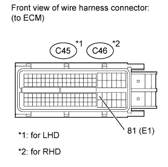
Standard Resistance for LHD Tester Connection Condition Specified Condition C45-81 (E1) - Body ground Always Below 1 Ω for RHD Tester Connection Condition Specified Condition C46-81 (E1) - Body ground Always Below 1 Ω
NG
REPAIR OR REPLACE HARNESS OR CONNECTOR
OK
-
-
INSPECT ECM (IGSW VOLTAGE)
-
Disconnect the ECM connectors.
-
Turn the engine switch on (IG).
-
Measure the voltage according to the value(s) in the table below.
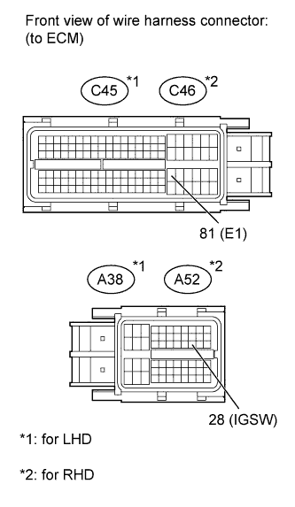
Standard Voltage for LHD Tester Connection Switch Condition Specified Condition A38-28 (IGSW) - C45-81 (E1) Engine switch on (IG) 11 to 14 V for RHD Tester Connection Switch Condition Specified Condition A52-28 (IGSW) - C46-81 (E1) Engine switch on (IG) 11 to 14 V
NG 
INSPECT FUSE (IGN) Click here
OK 
REPLACE ECM Click here
-
-
INSPECT FUSE (IGN)

-
Remove the IGN fuse from the engine room relay block.
-
Measure the resistance according to the value(s) in the table below.
Standard Resistance Tester Connection Condition Specified Condition IGN fuse Always Below 1 Ω
NG
CHECK FOR SHORT IN ALL HARNESSES AND CONNECTORS CONNECTED TO FUSE AND REPLACE FUSE
OK
-
-
CHECK HARNESS AND CONNECTOR (INTEGRATION RELAY - ECM, INTEGRATION RELAY - BODY GROUND)

-
Remove the integration relay from the engine room relay block.
-
Disconnect the ECM connector.
-
Measure the resistance according to the value(s) in the table below.
Standard Resistance for LHD Tester Connection Condition Specified Condition 1B-8 - A38-28 (IGSW) Always Below 1 Ω 1B-8 or A38-28 (IGSW) - Body ground Always 10 kΩ or higher for RHD Tester Connection Condition Specified Condition 1B-8 - A52-28 (IGSW) Always Below 1 Ω 1B-8 or A52-28 (IGSW) - Body ground Always 10 kΩ or higher
NG
REPAIR OR REPLACE HARNESS OR CONNECTOR
OK
-
-
CHECK HARNESS AND CONNECTOR (MAIN BODY ECU - ENGINE ROOM RELAY BLOCK)
-
Remove the integration relay from the engine room relay block.
-
Disconnect the E2 main body ECU connector.
-
Measure the resistance according to the value(s) in the table below.
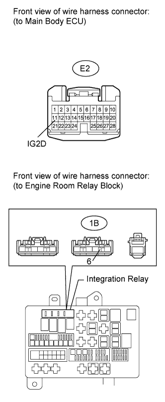
Standard Resistance Tester Connection Condition Specified Condition E2-11 (IG2D) - 1B-6 Always Below 1 Ω E2-11 (IG2D) or 1B-6 - Body ground Always 10 kΩ or higher
NG
REPAIR OR REPLACE HARNESS OR CONNECTOR
OK
-
-
CHECK ENTRY AND START SYSTEM (POWER SOURCE MODE DOES NOT CHANGE)
-
Check the entry and start system Click here.
NG
REPAIR ENTRY AND START SYSTEM
OK
REPLACE ECM Click here
-